Table of Contents
Advertisement
Quick Links
Advertisement
Table of Contents

Subscribe to Our Youtube Channel
Related Manuals for TECSYSTEM NT935-4


Summary of Contents for TECSYSTEM NT935-4
- Page 1 INSTRUCTION MANUAL NT935-4 1MN0102 REV. 0 operates with ISO9001 certified quality system TECSYSTEM S.r.l. 20094 Corsico (MI) Tel.: +39-024581861 Fax: +39-0248600783 http://www.tecsystem.it R. 1.1 29/09/17 ENGLISH “Translations of the original instructions”...
-
Page 2: Table Of Contents
INTRODUCTION First of all we wish to thank you for choosing to use a TECSYSTEM product and recommend you read this instruction manual carefully: You will understand the use of the equipment and therefore be able to take advantage of all its functions. - Page 3 PAGE …….……………………………. 8) RS485 MODBUS (only for NT935-4 AD) INTRODUCTION TO THE MODBUS INSIDE — ………………………………….. MODULE — ………………………………….. OPERATING NOTES — ………………………………….. DATA TRANSMISSION ON MODBUS NETWORK — ………………………………….. RS485 ELECTRICAL CONNECTIONS — ………………………………….. ...
-
Page 4: Safety Requirements
FUNCTION To control the transformer correctly from a temperature point of view, enabling the VOTING function is allowed where the load distributed between the phases of the transformer is adequately balanced. TECHNICAL INFORMATION Mail: ufficiotecnico@tecsystem.it — tel: 02/4581861 NT935-4 ASERIES... -
Page 5: Accessories
Code: 2PL0366 - Screws tightening torque 0.25Nm (*) only for NT935 AD version ATTENTION: always install the device using the terminals included in the pack. The use of terminals other than those included with the control unit might cause malfunctions. NT935-4 SERIES... -
Page 6: Technical Specifications
NT935-4 BASIC NT935-4 AD TECHNICAL SPECIFICATIONS POWER SUPPLY 24-240 Vac-Vdc 24-240 Vac-Vdc Supply rated values 50/60HZ 50/60HZ 20-270 Vac-Vdc 20-270 Vac-Vdc Maximum and minimum supply values 50/60HZ 50/60HZ ● ● Vdc with reversible polarities INPUTS ● ● 4 inputs for RTD sensors, Pt100 type with 3 wires (max section 1.5mm²) ●... - Page 7 TECHNICAL SPECIFICATIONS NT935-4 BASIC NT935-4 AD ● ● Housing NORYL 94 _V0 ● ● Absorption 7,5VA ● ● Data memory 10 years minimum ● ● Digital linearity of sensor signal ● ● Self-diagnostic circuit Protection treatment of the electronic part...
-
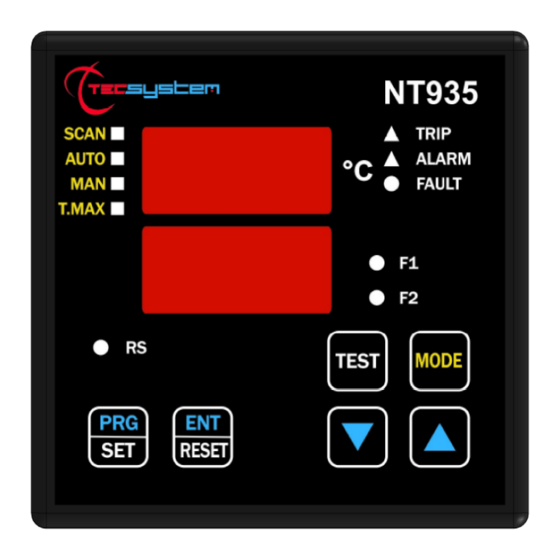
Page 8: Front Panel
FAN 1 (yellow) LED T-max mode selection (red) LED FAN 2 (yellow) LED Man mode selection (yellow) LED Display mode selection key Auto mode selection (green) LED Fixing block Scan mode selection (yellow) LED UP key Fixing block DOWN key NT935-4 ASERIES... -
Page 9: Display
The first display is dedicated to temperatures The second display to the monitored channel. When switching the device ON or following a reset, the display shows: the NT935-4 control unit model, sensor type, VER "00" (firmware version), BAS (no option) or AD and temperature range. -
Page 10: Mounting
Drill a 92 x 92 mm hole in the panel sheet. 1MN0007 REV. 0 Control unit Panel hole dimensions (+0.8mm tolerance) Identification label Fix the unit securely with the blocks supplied. 1MN0008 REV. 0 Control unit Fixing screw Fixing block Crosshead screwdriver #1X100mm NT935-4 ASERIES... -
Page 11: Electrical Connections Nt935-4 Basic
ELECTRICAL CONNECTIONS NT935-4 BASIC Pt100 sensors (white-red-red) Relays (FAN2-FAN1-ALARM-TRIP-FAULT) Supply 24-240Vac-dc 50/60Hz. Note: relay contact image in non-alarm condition, with the exception of the FAULT relay that opens: contacts 11-12 open (NO) contacts 11-12 closed (NC) fault condition identification. Read the Alarms and Ventilation paragraph on page 13 3 and see the opening of the fault contact. -
Page 12: Nt935-4 Ad Back
ELECTRICAL CONNECTIONS NT935-4 AD Pt100 sensors (white-red-red) Relays (FAN2-FAN1-ALARM-TRIP-FAULT) Supply 24-240Vac-dc 50/60Hz. Output 4.20 mA Modbus RTU RS485 output Note: relay contact image in non-alarm condition, with the exception of the FAULT relay that opens: contacts 11-12 open (NO) contacts 11-12 closed (NC) fault condition identification. Read the Alarms and Ventilation paragraph on page 13 and see the opening of the fault contact. -
Page 13: Power Supply
POWER SUPPLY The NT935-4 control unit has UNIVERSAL power supply, i.e. it can be supplied by 24 to 240 Vac-Vdc, 50/60Hz irrespectively of polarity in Vdc (terminals 40-42). This is obtained thanks to the use of a tested power supply unit, newly designed and manufactured, that frees installers from worrying about the correct Vac and Vdc supply. -
Page 14: Programming
PROGRAMMING NT935-4 BASIC/AD STEP PRESS EFFECT PRESS NOTES Keep the PRG key pressed until the display shows PRG Select PRG SET for entering in the programming mode or PRG 1 default value PRG 1 to restore the default programmed value. - Page 15 HOT: the hottest channel Default HOT END is displayed End of programming Press ENT to save the set data Err: incorrect programming of and exit programming the LED values (note 6) See programming notes on page Return to step 1 NT935-4 SERIES...
-
Page 16: Programming Notes
/ electrical fault of the Pt100 sensors c) damage to the Pt100 inputs of the control unit. TECSYSTEM S.r.l. has designed its own special cable to transfer the measurement signals, CEI-compliant, with all the protection requirements provided for: model CT-ES... -
Page 17: Temperature Sensor Diagnostics
CAL message display: it appears when damage is found in the measurement circuit. The temperature values displayed might be incorrect. Return the control unit to TECSYSTEM for repairs. VOTING FUNCTION The voting function derives from the redundancy concept that consists in duplicating the components of a system to increase their reliability. -
Page 18: Temperature Diagnostics
The high flexibility of the NT935-4 allows you to select, for each channel, an operation mode for contact management of FAN1 and FAN2. During the programming of the individual channel, enabled, you will be asked to select one of the following ways to activate FAN, dedicated to that channel: ... -
Page 19: Rs485 Modbus (Only For Nt935-4 Ad)
RS485 MODBUS OUTPUT (ONLY FOR NT935-4 AD) INTRODUCTION TO THE MODBUS INSIDE MODULE The MODBUS INSIDE expansion module is built in the monitoring unit and allows data transfer on a RS485 line with MODBUS RTU protocol, maximum 32 devices. OPERATING NOTES For the module to work correctly, it is necessary to set the RS485 network set-up parameters: address, baud rate, parity bit. -
Page 20: Function Code
If the data are correct, they are transferred into the non-volatile memory (E2PROM), historical data are cancelled (Tmax=0°C) and, then, a system RESET is forced. If the WRITE command entails only writing "COMMANDS", it will be performed autonomously and without a RESET, that is without affecting the control unit data. NT935-4 ASERIES... -
Page 21: Error Codes
More frequent polling can overload the system without any benefit whatsoever. In multi-device RS485 lines, interrogated in sequence, it may be useful to enter a delay between polls in relation to: the number of connected devices, the communication speed and the number of read registers. NT935-4 SERIES... -
Page 22: Modbus Mapping Table
HFN (Fan test) 0=No test 1÷200h temperature 0=No FCD increment 1÷30°/sec 0=No Voting Voting 1=YES CPU Setting See Note CPU Error See Note See Note Relays Status reference 0=hot 420 mA channel channel for 4.20 1÷4= ch1÷4 5=scan NT935-4 ASERIES... - Page 23 1°C÷200°C (*) 2’compl. Ch2 temper. 1°C ÷ 240°C 2’compl. sign As (TRP) trip set point 1°C÷200°C (*) –10°C ÷ 240°C 2’compl. sign 2’compl. Ch3 temper. –48°C÷200°C (*) 0°C ÷ 240°C 2’compl. sign 2’compl. Ch3 max temperat. 0°C÷200°C (*) NT935-4 SERIES...
- Page 24 0°C÷200°C (*) 2’compl. Ch4 temper. 1°C ÷ 240°C 2’compl. sign As (AL) alarm set point 1°C÷200°C (*) 2’compl. Ch4 temper. 1°C ÷ 240°C 2’compl. sign As (TRP) trip set point 1°C÷200°C (*) (*) for version –40°C ÷ +200°C NT935-4 ASERIES...
- Page 25 Data HI Data LO Note 1 Note 2 (10) read/write Ch1 story Ch1 status See Note CHx Ch2 story Ch2 status See Note CHx Ch3 story Ch3 status See Note CHx Ch4 story Ch4 status See Note CHx NT935-4 SERIES...
- Page 26 BIT 4 BIT 3 BIT 2 BIT 1 BIT 0 PT ERROR FCD Fault CPU SETTING BIT 7 BIT 6 BIT 5 BIT 4 BIT 3 BIT 2 BIT 1 BIT 0 Failsafe Failsafe fault Failsafe trip alarm NT935-4 ASERIES...
-
Page 27: Fail Safe Function
FAIL SAFE FUNCTION The NT935-4 has n.o selection (contact open ) / n.c (normally closed contact) for ALARM, TRIP and FAULT relays, programming steps 26 to 31 page 15. The selection of the setting YES/NO introduces functions Fail Safe and No Fail Safe. -
Page 28: Fcd Function
The Product purchased is covered by the manufacturer's or seller's warranty at the terms and conditions set forth in the "Tecsystem s.r.l's General Conditions of Sale", available at www.tecsystem.it and / or in the purchase agreement. The warranty is considered valid only when the product is damaged by causes attributable to TECSYSTEM srl, such as manufacturing or components defects. -
Page 29: Troubleshooting
Returning used electrical devices: contact TECSYSTEM or your TECSYSTEM agent for information on the correct disposal of the devices. TECSYSTEM is aware of the impact its products have on the environment and asks its customers active support in the correct and environmentally-friendly disposal of its devices. -
Page 30: Ul Specification And Ratings
5 relay Output: 10A 250Vac-res COS=1 OUTPUTS RELAYS OPTIONAL PORTS (AD) RS485 + 4.20mA Suitable for use on a flat surface of a type 1 enclosure if Back panel is provided with two short fixing screws tightening torque : 0.57Nm NT935-4 ASERIES...
Need help?
Do you have a question about the NT935-4 and is the answer not in the manual?
Questions and answers