TECSYSTEM T154 Series Instruction Manual
Electronic microprocessor based unit for the temperature control of mv dry type and cast resin transformers
Hide thumbs
Also See for T154 Series:
- Manual (23 pages) ,
- Instruction manual (19 pages) ,
- Instruction manual (13 pages)
Table of Contents
Advertisement
Advertisement
Table of Contents

Related Manuals for TECSYSTEM T154 Series


Summary of Contents for TECSYSTEM T154 Series
- Page 1 INSTRUCTION MANUAL T154 SERIES 1MN0044 REV. 0 operates with ISO9001:2008 certified quality system TECSYSTEM S.r.l. 20094 Corsico (MI) Tel.: +39-024581861 Fax: +39-0248600783 http: //www.tecsystem.it R. 1.0 05/09/13 ENGLISH “Translations of the original instructions”...
-
Page 2: Table Of Contents
INTRODUCTION First of all we wish to thank you for choosing to use a TECSYSTEM product and recommend you read this instruction manual carefully: You will understand the use of the equipment and therefore be able to take advantage of all its functions. -
Page 3: Safety Requirements
POWER SUPPLY The T154 series has UNIVERSAL power supply, i.e. it can be supplied by 24 to 240 Vac-Vdc, irrespectively of polarity in Vdc. Before using it, make sure the power cable is not damaged, kinked or pinched. Do not tamper with the power cable. Never disconnect the unit by pulling the cable, avoid touching the pins. -
Page 4: Accessories
1 sensor terminal 12 poles pitch 5 Code: 2PL0361 1MN0030 REV. 0 ATTENTION: always install the device using the terminals included in the pack. The use of terminals other than those included with the control unit might cause malfunctions. T154 SERIES... -
Page 5: Technical Specifications
Hole 92 x 92 Hole 92 x 92 (terminal block included) TEST AND PERFORMANCE Construction in compliance with CE regulations ● ● ● ● ● Curus certificate ● ● ● ● ● Rina certificate Option Option Option Option Option T154 SERIES... - Page 6 ● ● ● ● Selection of automatic channel scanning, hottest channel or manual scanning ● ● ● ● ● Storage of maximum temperatures reached by channels and ● ● ● ● ● alarm status Front alarm reset button T154 SERIES...
-
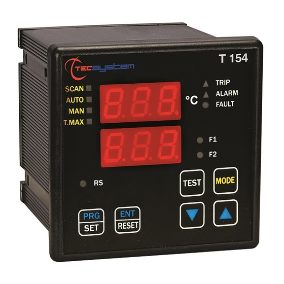
Page 7: Front Panel
FAULT warning (red) LED CH1-CH2-CH3-CH4 selected channel (green) LED Scanning mode selection button T-max mode selection (red) LED Fixing block Man mode selection (yellow) LED UP button Auto mode selection (green) LED DOWN button Scan mode selection (yellow) LED T154 SERIES... -
Page 8: Display
We recommend the unit LEDs are tested regularly. For this operation press the TEST button briefly, all the displays light up for 2 seconds. If one of the LEDS does not work, please return the control unit to TECSYSTEM for repair. ALARM RELAY TEST This function allows carrying out a test of the relay operation without having to use supplementary equipment. -
Page 9: Installation
Drill a 92 x 92 mm hole in the panel sheet. 1MN0007 REV. 0 Control unit Panel hole dimensions (+0.8mm tolerance) Identification label Fix the unit securely with the blocks supplied. 1MN0008 REV. 0 Control unit Fixing screw Fixing block Crosshead screwdriver #1X100mm T154 SERIES... -
Page 10: Electrical Connections
ALARMS AND VENTILATION on page 11 and see the fault contact switching picture below. FAULT CONTACT SWITCHING 7 8 9 7 8 9 FAULT 8-9 NC: ALARM FAULT OR POWER OFF FAULT 7-9: NC POWER ON RELAY CONNECTION EXAMPLE 1MN0095 REV. 0 Ф Output relay with 5A-250Vac-res COS =1 contacts. T154 SERIES... -
Page 11: Power Supply
To protect the control unit from line overvoltages, we recommend using the electronic PT-73-220 surge limiter, designed by TECSYSTEM S.r.l. specifically for this purpose. Alternatively we recommend to adopt 24 Vac or, even better, 24 Vdc supply voltages. -
Page 12: Programming
FAN switching on The ON threshold of the FANS is displayed Set the desired threshold Default 70°C(158°F) OFF is displayed FAN switching off The OFF threshold of the FANS is displayed Set the desired threshold Default 60°C(140 °F) T154 SERIES... - Page 13 ATTENTION: We recommend you check the control unit before starting the device. The default parameters set by TECSYSTEM might not suit your requirements. Programming the device is the end user’s responsibility: the set alarm thresholds and the enabled functions described in this manual must be checked (by a specialized technician) referring them to the application and system characteristics on which the control unit is installed.
-
Page 14: T154 -4 / T154 -4 Fahrenheit
FAN switching on The ON threshold of the FANS is displayed Set the desired threshold Default 70°C(158°F) OFF is displayed FAN switching off The OFF threshold of the FANS is displayed Set the desired threshold Default 60°C(140 °F) T154 SERIES... - Page 15 ATTENTION: We recommend you check the control unit before starting the device. The default parameters set by TECSYSTEM might not suit your requirements. Programming the device is the end user’s responsibility: the set alarm thresholds and the enabled functions described in this manual must be checked (by a specialized technician) referring them to the application and system characteristics on which the control unit is installed.
-
Page 16: Measurement Signal Transfer
NOTE: to install the sensors and signal transferring cable correctly, read the sensor and SCS installation note manual. TECSYSTEM S.r.l. has designed its own special cable to transfer the measurement signals, CEI-compliant, with all the protection requirements provided for: model CT-ES 1MN0035 REV. -
Page 17: Programmed Data Diagnostics
Eliminate the Ech message by pressing RESET and enter the desired values. Finally switch the unit off and back on to check the memory works correctly, if it is damaged Ech will be displayed again (send the control unit to TECSYSTEM srl for repair). TEMPERATURE DIAGNOSTICS When one of the temperature sensors senses a temperature 1°C higher than the alarm threshold, 5 seconds later the... -
Page 18: Technical Specifications Of The Extension Cable For
In this specific case we recommend the FCD function to be set in a temperature range of between 20°C and 30°C. This setting is recommended in order to prevent the FCD function from activating during motor startup, or where the ΔT/sec. increase varies quickly. (*) The ΔT value shows the temperature range for each second. T154 SERIES... -
Page 19: Warranty Regulations
Returning used electrical devices: contact TECSYSTEM or the TECSYSTEM agent for information on the correct disposal of the devices. TECSYSTEM is aware of the impact its products have on the environment and asks its customers active support in the correct and environmentally-friendly disposal of its devices. - Page 20 USEFUL CONTACT TECHNICAL INFORMATION: ufficiotecnico@tecsystem.it COMMERCIAL INFORMATION: info@tecsystem.it PRODUCT INFORMATION (CATALOGUES) DOWNLOAD CONTROL UNIT MANUALS ACCESSORIES UL RATINGS INPUT SUPPLY 24 – 240 Vac / Vdc, 50/60 Hz, 12 VA max Vac , 5 A with resistive load, 30'000 cycles ,...
Need help?
Do you have a question about the T154 Series and is the answer not in the manual?
Questions and answers