Table of Contents
Advertisement
Quick Links
Advertisement
Table of Contents

Related Manuals for TECSYSTEM NT935 ETH


Summary of Contents for TECSYSTEM NT935 ETH
- Page 1 INSTRUCTION MANUAL NT935 ETH 1MN0121 REV. 0 operates with ISO9001 certified quality system TECSYSTEM S.r.l. 20094 Corsico (MI) Tel.: +39-024581861 Fax: +39-0248600783 http://www.tecsystem.it R. 1.5 06/09/17 ENGLISH “Translations of the original instructions”...
- Page 2 INTRODUCTION First of all we wish to thank you for choosing to use a TECSYSTEM product and recommend you read this instruction manual carefully: You will understand the use of the equipment and therefore be able to take advantage of all its functions.
-
Page 3: Table Of Contents
11) TECHNICAL SPECIFICATIONS OF THE EXTENSION ………………………………….. CABLE FOR Pt100 ………………………………….. 12) FCD FUNCTION — ………………………………….. 13) WARRANTY CONDITIONS ………………………………….. 14) TROUBLESHOOTING — ………………………………….. 15) EQUIPMENT DISPOSAL — ………………………………….. 16) USEFUL CONTACTS ………………………………….. 17) UL SPECIFICATION AND RATINGS NT935 ETH... - Page 4 POWER SUPPLY The NT935 ETH control unit has UNIVERSAL power supply, i.e. it can be supplied from 85 to 260 Vac-Vdc, irrespectively of polarity in Vdc. Before use, ensure that the power cable is not damaged, knotted or pinched. Do not tamper with the power cable.
- Page 5 1 Pt100 sensors terminal 12 poles pitch 3.81 Code: 2PL0420 - Screws tightening torque 0.25Nm ATTENTION: always install the device using the terminals included in the pack. The use of terminals other than those included with the control unit might cause malfunctions. NT935 ETH...
- Page 6 NT935 ETH TECHNICAL SPECIFICATIONS POWER SUPPLY 85-260 Vac-Vdc Supply rated values 50/60HZ ● Vdc with reversible polarities INPUTS ● 4 inputs for RTD sensors, Pt100 type with 3 wires (max section 1.5mm²) ● Connections on removable terminal strips ● Input channels protected against electromagnetic interference Cable compensation for thermistors 500m (1mm²)
- Page 7 TECHNICAL SPECIFICATIONS NT935 ETH ● Housing NORYL 94 _V0 ● Absorption 7,5VA ● Data memory 10 years minimum ● Digital linearity of sensor signal ● Self-diagnostic circuit Protection treatment of the electronic part Option DISPLAY AND DATA MANAGEMENT ● 2x13mm displays with 3 digits to display temperatures, messages and channels ●...
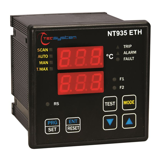
- Page 8 FAN 1 (yellow) LED T-max mode selection (red) LED FAN 2 (yellow) LED Man mode selection (yellow) LED Display mode selection key Auto mode selection (green) LED Fixing block Scan mode selection (yellow) LED UP key Fixing block DOWN key NT935 ETH...
- Page 9 The first display is dedicated to temperature.s The second display to the monitored channel. When the device is switched on or following a reset, the display shows: the control unit model, NT935 ETH, together with VER "00" (firmware version) and temperature range of the device.
- Page 10 Drill a 92 x 92 mm hole in the panel sheet. 1MN0007 REV. 0 Control unit Panel hole dimensions (+0.8mm tolerance) Identification label Fix the unit securely with the blocks supplied. 1MN0008 REV. 0 Control unit Fixing screw Fixing block Cross-head screwdriver #1X100mm NT935 ETH...
- Page 11 ELECTRICAL CONNECTIONS NT935 ETH Pt100 sensors (white-red-red) Relays (FAN2-FAN1-ALARM-TRIP-FAULT) Supply 85-260Vac-dc 50/60Hz. RJ45 Ethernet output, Link-Activity LED, see indication on page 30. Note: relay contact image in non-alarm condition, with the exception of the FAULT relay that opens: contact 11-12 open (NO) contacts 11-12 closed (NC) fault condition identification.
- Page 12 To protect the control unit from line overvoltages, we suggest using the PT-73- 220 electronic discharger, designed by TECSYSTEM S.r.l. for this specific purpose. As an alternative we suggest using 110 Vac or, even better, 110 Vdc supply voltages.
- Page 13 PROGRAMMING NT935 ETH STEP PRESS EFFECT PRESS NOTES Keep the PRG key pressed until the display shows PRG Select PRG SET for entering in the programming mode PRG 1 default value or PRG 1 to restore the default programmed value.
- Page 14 = INT FAN-OFF ≥ FAN-ON (FAN1) DELTA <10°C ERR INT The device automatically switches to the programming step of the mistake. NOTE: EVERY TIME THE CONTROL UNIT IS PROGRAMMED WITH DATA SAVING CONFIRMATION, THE VALUES STORED IN T-MAX ARE RESET TO THE TIME OF SAVING. NT935 ETH...
- Page 15 / electrical fault of the Pt100 sensors c) damage to the Pt100 inputs of the control unit. TECSYSTEM S.r.l. has designed its own special cable to transfer the measurement signals, CEI-compliant, with all the protection requirements provided for: model CT-ES NOTE: the use of cables not complying with the above might cause reading anomalies.
- Page 16 VOTING (see below) or FCD (see page 31) according to the conditions of the system. CAL message display: it appears when damage is found in the measurement circuit. The temperature values displayed might be incorrect. Return the control unit to TECSYSTEM for repairs. VOTING FUNCTION The voting function derives from the redundancy concept that consists in duplicating the components of a system to increase their reliability.
- Page 17 COOLING FAN CONTROL The NT935 ETH control unit is fitted with two FAN controls (FAN1 and FAN2) and, if programmed correctly, can control the fans switching ON and OFF to cool the transformer. The FAN1 and FAN2 contacts can manage cooling the transformer and the room where it is installed.
- Page 18 The ETH module is always in slave mode. The NT935 ETH control unit is in communication with the network only when it is in temperature reading mode, while it is inactive when in the following modes: display, programming and relay test.
-
Page 19: Notes For Remote Programming
Trip thresholds and that the Fan-on thresholds must be higher than the Fan-off thresholds. If you try to set these thresholds wrongly, the NT935 ETH monitoring unit won’t proceed with programming and data storage; therefore in the following readings you will read the data relevant to the previous programming. -
Page 20: Illegal Data
Vers. Fw – MSD(ASCII) Space (20H) Vers. Fw – LSD(ASCII) Vers. Fw - 2° Digit (ASCII) Channels qty (2*ASCII) (Options see note) Options (see note) Wrong datum received R-see tab. Info various causes R-see tab Commands W-see tab. NT935 ETH... - Page 21 1° to÷ 240° 2’compl. sign Fan_1 OFF 1°C ÷ 200°C (*) 1° to÷ 240° 2’compl. sign Fan_2 ON 1°C ÷ 200°C (*) 1° to÷ 240° 2’compl. sign Fan_2 OFF 1°C ÷ 200°C(*) (*) for version –40°C ÷ +200°C NT935 ETH...
- Page 22 2’compl. Ch4 max temperat. 0°C÷200°C (*) 2’compl. Ch4 temper. 1°C ÷ 240°C 2’compl. sign alarm set point 1°C÷200°C (*) 2’compl. Ch4 temper. 1°C ÷ 240°C 2’compl. sign trip set point 1°C÷200°C (*) (*) for version –40°C ÷ +200°C NT935 ETH...
- Page 23 CHANNELs 1÷4: Setting R: read Address LO Data HI Data LO Note 1 Note 2 W:write (10) RW: read/write Ch1 Setting See Note CHx Ch2 Setting See Note CHx Ch3 Setting See Note CHx Ch4 Setting See Note CHx NT935 ETH...
- Page 24 BIT 5 BIT 4 BIT 3 BIT 2 BIT 1 BIT 0 FAN_INT FAN2 FAN1 CAN_enabl CHn STATUS BIT 6 BIT 5 BIT 4 BIT 3 BIT 2 BIT 1 BIT 0 BIT 7 TRIP ALARM FAN_2 FAN_1 NT935 ETH...
-
Page 25: Fail Safe Function
FAIL SAFE FUNCTION The NT935 ETH has n.o selection (contact open ) / n.c (normally closed contact) for ALARM, TRIP and FAULT relays, programming steps 30 to 35 page 14. The selection of the setting YES/NO introduces functions Fail Safe and No Fail Safe. -
Page 26: Ethernet Module Parameter Programming
X Windows Vista, 7, 8. ETH0 CONNECTIONS Using an Ethernet cable, connect the RJ45 ETH0 of the NT935 ETH control unit to the ethernet card of a PC. TELNET ENABLING Use the Telnet program to set the Ethernet IP parameters. -
Page 27: Telnet Screen
13) Enter: OPEN 14) Press ENTER 192.168.10.120 9999 15) Enter: 16) Press ENTER 17) Enter the Password: TECS 18) Press ENTER Note: In this screen we have the MAC address and the software version of the ETH port available. NT935 ETH... -
Page 28: Ip Parameter Programming Menu
IMPORTANT WARNING For the device to work correctly, we advise you not to access or modify menus 2-3-4-7. The modification of the values in the stated menus might cause communication anomalies with the loss of the Ethernet IP communication. NT935 ETH... - Page 29 3) Enter the new Netmask, press ENTER; if you wish to keep the set address press ENTER 4 times. At the end of the operation, the system will ask if you wish to modify the Telnet Password: Enter: to modify the Telnet Password. not to modify the Telnet Password and go to the following step. NT935 ETH...
-
Page 30: Technical Specifications Of The Extension Cable For Pt100
4. CEI 20.35 IEC 332.1 regulations 5. Maximum operating temperature: 90°C 6. Conformation: 4 sets of three twisted and coloured conductors 7. Shield in Cu/Sn 8. Flame retardant PVC sheath 9. External diameter 12mm 10. Standard conformation in 100m coils NT935 ETH... -
Page 31: Fcd Function
The Product purchased is covered by the manufacturer's or seller's warranty at the terms and conditions set forth in the "Tecsystem s.r.l's General Conditions of Sale", available at www.tecsystem.it and / or purchase agreement. The warranty is considered valid only when the product is damaged by causes attributable to TECSYSTEM srl, such as manufacturing or components defects. -
Page 32: Troubleshooting
Returning used electrical devices: contact TECSYSTEM or your TECSYSTEM agent for information on the correct disposal of the devices. TECSYSTEM is aware of the impact its products have on the environment and asks its customers active support in the correct and environmentally-friendly disposal of its devices. -
Page 33: Ul Specification And Ratings
External switch or circuit breaker 5 relay output: 10A 250Vac-res COS=1 OUTPUTS RELAYS PORT Ethernet Suitable for use on a flat surface of a type 1 enclosure if Back panel is provided with two short fixing screws tightening torque : 0.57Nm NT935 ETH...
Need help?
Do you have a question about the NT935 ETH and is the answer not in the manual?
Questions and answers