Advertisement
Quick Links
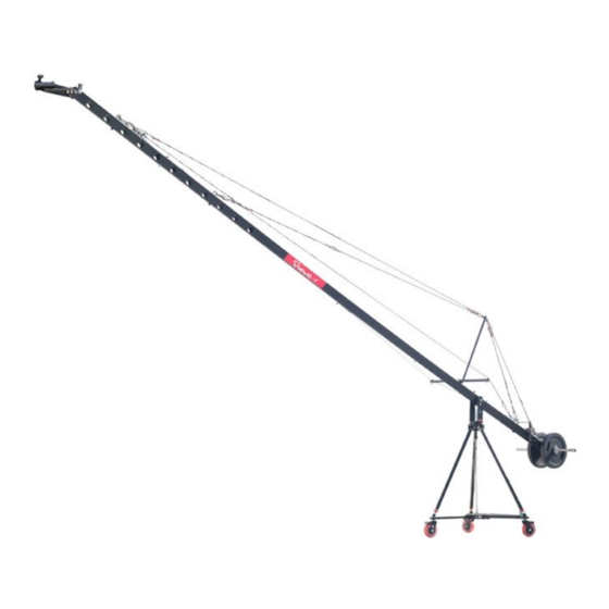
24ft Camera Crane Base Kit
(
P-W5P24-BASE)
I N S T R U C T I O N M A N U A L
All rights reserved
No part of this document may be reproduced, stored in a retrieval system, or transmitted by any form or by any
means, electronic, mechanical, photocopying, recording, or otherwise, except as may be expressly permitted by the
applicable copyright statutes or in writing by the Publisher.
Advertisement

Related Manuals for PROAIM P-W5P24-BASE


Summary of Contents for PROAIM P-W5P24-BASE
- Page 1 24ft Camera Crane Base Kit P-W5P24-BASE) I N S T R U C T I O N M A N U A L All rights reserved No part of this document may be reproduced, stored in a retrieval system, or transmitted by any form or by any means, electronic, mechanical, photocopying, recording, or otherwise, except as may be expressly permitted by the applicable copyright statutes or in writing by the Publisher.
-
Page 2: What's In The Box
LINE' BY CONTACTING YOUR SALES REPRESENTATIVE. INTRODUCTION PROAIM 24 ' Base Kit is a complete production package for those who do not believe in compro- mise. It is designed to extend your reach and to explore every unexplored angle. The hi grade alu- minum construction enables fast set-up &... - Page 3 Safety chain Please use following sequence of pictures and text in order they appear to set up your new PROAIM 24FT BASE KIT. Technical assistance is available by contacting our sales representa- tive. ASSEMBLING D-37 DOLLY & TRIPOD STAND ...
- Page 4 PROAIM 24ft BASE KIT Attach dolly platform to D-37, screw in the Allen bolts to desired positions and tighten all the connections with the help of Allen key. Attach the legs of tripod stand with D-37 dolly as shown in the image.
- Page 5 PROAIM 24ft BASE KIT Wire tensioner and safety chain setup should be properly aligned to ensure sta- bility. ASSEMBLING JIB SECTIONS Install the 5th Section to the rear of the vertical pivot point through bolt, washers and nut.
- Page 6 PROAIM 24ft BASE KIT ASSEMBLING CABLE GUIDE AND ROD SUPPORT Attach cable guide to cable guide clamp on 5th section properly. Loosen the bolts on cable guide clamp in order to attach cable guide support rod to it. Retighten the bolt.
- Page 7 PROAIM 24ft BASE KIT Attach 2 hooks on both slots on cable guide. Then attach two extra hooks to hook attach to front side and two hooks to hook attached on back side. ASSEMBLING CABLES Now attach one end of 2.2ft cable with Red Sleeves to hook on back side of cable guide and another end to hook on 1st slot on jib section with the help of wire tensioner.
- Page 8 PROAIM 24ft BASE KIT Now join 3.7ft cable & 6.7ft Cable with Red Sleeves. Attach the end of 6.7ft cable to one of the hook attached on front side of cable guide and another end of 3.7ft cable with hook attached to 3rd section of jib.
- Page 9 PROAIM 24ft BASE KIT INSTALLING THE HEAD PLATFORM Install the Head Platform assembly (leveling arm up) to the end of the smallest section with the provided bolt, shaft collars, washers and nut. Tighten all the Allen bolts and nuts to secure properly.
- Page 10 Attach LCD mount L-bracket to bracket already attached to rear section with knob. Now mount LCD (not included) to L-bracket and tighten with screw driver. YOUR PROAIM 24ft CAMERA CRANE BASE KIT ALL DRESSED UP AND READY TO GO (SHOWN WITH OTPIONAL ACCESSORIES)
-
Page 11: Warranty
PROAIM 24ft BASE KIT WARRANTY We offer a one year warranty for our products from the date of purchase. We will repair or replace your product, free of charge, in the event of a defect in materials or craftsmanship obtained during normal use or handling based on the user manual. Please note that we will not cover any shipping costs for returning the product to us.
Need help?
Do you have a question about the P-W5P24-BASE and is the answer not in the manual?
Questions and answers