Table of Contents
Advertisement
We,
Hisense(Shandong) Air-conditioning Co.,Ltd.
No.8 Ronggang Road, Ronggui, Shunde,Foshan, Guangdong, P.R.China
No.1 Hisense Road, Nancun, Pingdu,Qingdao, Shandong Province, P.R.China
declare under our sole responsibility that the product
to which this declaration relates is in conformity with the technical requirements of the
following standard(s)
EMC Directive- 2014/30/EU
Low Voltage Directive-2014/35/EU
CE Marking Directive-93/68/EEC
LVD standard
EN 60335-1:2012+A11:2014
EN 60335-2-40:2003
+A11:2004+A12:2005+A1:2006+A2:2009
+A13:2012
EN 62233:2008
Hisense International Co., Ltd
( Supplier Address & Factory Address )
AIR CONDITIONER
(Category Name)
GBF18H-S
GDF18H-S
GBF24H-S
GDF24H-S
GBF36H-S
GDF36H-S
GBF48H-S
GDF48H-S
GBF60H-S
GDF60H-S
(Model Name)
GFF18H-S
GCF18H-S
GFF24H-S
GCF24H-S
GFF36H-S
GCF36H-S
GFF48H-S
GCF48H-S
GFF60H-S
GCF60H-S
EMC standard
EN 55014-1:2006
+A1:2009+A2:2011
EN 55014-2:1997 +A1:2001+A2:2008
EN 61000-3-2:2014
EN 61000-3-2:2014
EN 61003-3-3:2013
Advertisement
Table of Contents

Subscribe to Our Youtube Channel
Related Manuals for Hisense GBF18H-S


Summary of Contents for Hisense GBF18H-S
- Page 1 Hisense International Co., Ltd Hisense(Shandong) Air-conditioning Co.,Ltd. No.8 Ronggang Road, Ronggui, Shunde,Foshan, Guangdong, P.R.China No.1 Hisense Road, Nancun, Pingdu,Qingdao, Shandong Province, P.R.China ( Supplier Address & Factory Address ) declare under our sole responsibility that the product AIR CONDITIONER (Category Name)
- Page 2 We, hereby further declare that the following products (Product catalog) are exactly the same, only difference being the art work. Client Model Factory Model No. Brand Type/Description/Feature AUC-18HR4SAA GBF18H-S Galactic R410a, On/Off, 18000Btu,CASSETTE type indoor unit AUC-24HR4SGA GBF24H-S Galactic R410a, On/Off, 24000Btu,CASSETTE type indoor unit...
- Page 3 1-1 Features Duct Type Air Conditioner Features Save Installation Space ➢ The indoor unit can be installed inside the ceiling conveniently. Optional Static Pressure ➢ 18k: optional 10Pa /30Pa, 24K/36K 50Pa/80Pa 48K/60K: 80Pa/120Pa static Pressure. One unit, mute optional installation method. High Efficiency and Environment Friendly New Refrigerant-R410A ➢...
- Page 4 Self Recovery of Power Break ➢ When the power supply is recovered after break, all preset are still effective and the air-conditioner can run according to the original setting. Fault Self-diagnose Function ➢ When there is something wrong with the air-conditioner,the micro computer could diagnose the faults, which can be read from the display and is convenient for maintenance.
- Page 5 Cassette Type Air Conditioner Features Save Installation Space ➢ The indoor unit can be installed inside the ceiling conveniently. High Efficiency and Environment Friendly New Refrigerant-R410A ➢ R410A can protect the environment and do not harm to the ozone layer. 24-hour Timer ON and OFF ➢...
- Page 6 Ceiling &Floor Air Conditioner Features Save Installation Space ➢ The indoor unit’s thickness is only 230mm,can be installed inside the ceiling conveniently. Flexible Installation Options ➢ According to the actual installation space,The indoor unit can be installed in the ceiling or on the floor.
- Page 7 When there is something wrong with the air-conditioner, the micro computer could diagnose the faults, which can be read from the display and is convenient for maintenance. ON/OFF UNITARY AIR CONDITIONER TECHNICAL& SERVICE MANUAL V6.0...
-
Page 8: Product Lineup
1-2 Product Lineup Type Model Duct Type AUD- ● ● ● ● ● Cassette Type AUC- ● ● ● ● ● Ceiling&Floor AUV- ● ● ● ● ● type ON/OFF UNITARY AIR CONDITIONER TECHNICAL& SERVICE MANUAL V6.0... -
Page 9: Model Identification
1-3 MODEL IDENTIFICATION A U C -18 U R 4 S Z A A 1 Serial Number K:Outdoor Unit Indetification G:Indoor Unit Indetification S:Refrigerant R410A F:Refrigerant R22 4:220V-240V/50HZ/1P 6:380V-415V/50HZ/3P X: Wire Remote Controller R:Wireless Remote Controller U:DC-Invert Heat Pump Type H:Heat Pump Type C:Cooling Only Cool Capacity:18x10 Btu/h Type:D-Duct Type,C-Cassette Type,V-Ceiling&Floor Type,W-Outdoor Unit Unit... -
Page 10: Product Picture
1-4 Product Picture Duct Type AUD-36HX6SAHH AUD-18HX4SUNL AUD-24HX4SZLH AUD-36HX6SAHH1 Model AUD-18HX4SUNL1 AUD-24HX4SZLH1 AUD-36HX6S1A1HH1 Indoor Outdoor AUD-48HX6SPHH Model AUD-48HX6SEHH1 AUD-60HX6SPHH AUD-60HX6SPHH1 Indoor Outdoor ON/OFF UNITARY AIR CONDITIONER TECHNICAL& SERVICE MANUAL V6.0... -
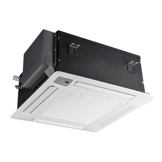
Page 11: Cassette Type
Cassette Type AUC-36HR6SAGA AUC-18HR4SUAA AUC-24HR4SZGA Model AUC-36HR6SAGA1 AUC-18HR4SUAA1 AUC-24HR4SZGA1 AUC-36HR6S1AGA1 Indoor Outdoor AUC-48HR6SPHA Model AUC-48HR6SEHA1 AUC-60HR6SPHA AUC-60HR6SPHA1 Indoor Outdoor ON/OFF UNITARY AIR CONDITIONER TECHNICAL& SERVICE MANUAL V6.0... -
Page 12: Ceiling&Floor Type
Ceiling&Floor Type AUV-36HR6SAB AUV-18HR4SUA AUV-24HR4SZA Model AUV-36HR6SAB1 AUV-18HR4SUA1 AUV-24HR4SZA1 AUV-36HR6S1AB1 Indoor Outdoor AUV-48HR6SPC Model AUV-48HR6SEC1 AUV-60HR6SPC AUV-60HR6SPC1 Indoor Outdoor ON/OFF UNITARY AIR CONDITIONER TECHNICAL& SERVICE MANUAL V6.0... -
Page 13: Display Panel
DISPLAY PANEL Cassette Type 24K,36K,48K,60K ON/OFF UNITARY AIR CONDITIONER TECHNICAL& SERVICE MANUAL V6.0... - Page 14 Ceiling&Floor type ON/OFF UNITARY AIR CONDITIONER TECHNICAL& SERVICE MANUAL V6.0...
-
Page 15: Specifications
2. Specifications 2.1Duct Type On/Off Unitary Indoor Unit AUD-18HX4SUNL AUD-24HX4SZLH AUD-36HX6SAHH AUD-48HX6SPHH AUD-60HX6SPHH Indoor model: AUD-18HX4SNL AUD-24HX4SLH AUD-36HX4SHH AUD-48HX4SHH AUD-60HX4SHH Outdoor model: AUW-18H4SU AUW-24H4SZ AUW-36H6SA AUW-48H6SP AUW-60H6SP Performance Cooling Capacity (W) 5000 7400 10200 14000 16000 Heating Capacity (W) 5500 7900 11250 15000... - Page 16 AUD-18HX4SUNL AUD-24HX4SZLH AUD-36HX6SAHH AUD-48HX6SPHH AUD-60HX6SPHH Indoor model: AUD-18HX4SNL AUD-24HX4SLH AUD-36HX4SHH AUD-48HX4SHH AUD-60HX4SHH Outdoor model: AUW-18H4SU AUW-24H4SZ AUW-36H6SA AUW-48H6SP AUW-60H6SP Dimensions Indoor WxHxD 900×190×447 900×270 ×720 1386×350×800 1386×350×800 1386×350×800 Unit (mm) Weight Indoor (Kg) Unit Packing Dimensions Indoor 1070X236X580 1170X340X870 1550×410×940 1550×410×940 1550×410×940 WxHxD...
- Page 17 On/Off Unitary Indoor Unit (Low temp.) AUD-18HX4SU AUD-24HX4SZL AUD-36HX6SA AUD-36HX6S1A AUD-48HX6SE AUD-60HX6S 1HH1 PHH1 AUD-18HX4SN AUD-24HX4SL AUD-36HX4SH AUD-36HX4S1H AUD-48HX4SH AUD-60HX4S Indoor model: AUW-36H6S1A AUW-60H6SP Outdoor model: AUW-18H4SU1 AUW-24H4SZ1 AUW-36H6SA1 AUW-48H6SE1 Performance Cooling Capacity (W) 5000 7400 10200 10200 14000 16000 Heating Capacity (W) 5500 7900...
- Page 18 AUD-18HX4SU AUD-24HX4SZL AUD-36HX6SA AUD-36HX6S1A AUD-48HX6SE AUD-60HX6S 1HH1 PHH1 AUD-18HX4SN AUD-24HX4SL AUD-36HX4SH AUD-36HX4S1H AUD-48HX4SH AUD-60HX4S Indoor model: AUW-36H6S1A AUW-60H6SP Outdoor model: AUW-18H4SU1 AUW-24H4SZ1 AUW-36H6SA1 AUW-48H6SE1 Dimensions Indoor 1386×350×80 900×190×447 900×270 ×720 1386×350×800 1386×350×800 1386×350×800 WxHxD (mm) Unit Weight Indoor (Kg) Unit Packing Indoor 1550×410×94...
- Page 19 2.2 Cassette Type On/Off Unitary Indoor Unit AUC-18HR4SUA AUC-24HR4SZ AUC-36HR6SA AUC-48HR6SP AUC-60HR6SPHA AUC-24HR4SG AUC-36HR4SG AUC-48HR4SH Indoor model: AUC-18HR4SAA AUC-60HR4SHA Outdoor model: AUW-18H4SU AUW-24H4SZ AUW-36H6SA AUW-48H6SP AUW-60H6SP Performance Cooling Capacity (W) 5000 7450 10000 14000 16000 Heating Capacity (W) 5500 7500 11000 14800 17500...
- Page 20 AUC-18HR4SUA AUC-24HR4SZ AUC-36HR6SA AUC-48HR6SP AUC-60HR6SPHA AUC-24HR4SG AUC-36HR4SG AUC-48HR4SH Indoor model: AUC-18HR4SAA AUC-60HR4SHA Outdoor model: AUW-18H4SU AUW-24H4SZ AUW-36H6SA AUW-48H6SP AUW-60H6SP Copper tube Copper tube Copper tube Copper tube and Copper tube and Condenser and Aluminum and Aluminum and Aluminum Aluminum Fin Aluminum Fin Other Panel...
- Page 21 On/Off Unitary Indoor Unit(Low Temp.) AUC-18HR4SU AUC-24HR4S AUC-36HR6S AUC-36HR6S AUC-48HR6S AUC-60HR6 ZGA1 AGA1 1AGA1 EHA1 SPHA1 AUC-18HR4SA AUC-24HR4S AUC-36HR4S AUC-36HR4S AUC-48HR4S AUC-60HR4 Indoor model: AUW-36H6SA AUW-36H6S1 AUW-48H6SE AUW-60H6 Outdoor model: AUW-18H4SU1 AUW-24H4SZ Panel: PE-BA-B29 PE-CA-B29 PE-CA-B29 PE-CA-B29 PE-CA-B29 PE-CA-B29 Performance Cooling Capacity (W) 5000 7450...
- Page 22 AUC-18HR4SU AUC-24HR4S AUC-36HR6S AUC-36HR6S AUC-48HR6S AUC-60HR6 ZGA1 AGA1 1AGA1 EHA1 SPHA1 AUC-18HR4SA AUC-24HR4S AUC-36HR4S AUC-36HR4S AUC-48HR4S AUC-60HR4 Indoor model: AUW-36H6SA AUW-36H6S1 AUW-48H6SE AUW-60H6 Outdoor model: AUW-18H4SU1 AUW-24H4SZ Panel: PE-BA-B29 PE-CA-B29 PE-CA-B29 PE-CA-B29 PE-CA-B29 PE-CA-B29 Aluminum Other Dimension Panel 650x30x650 950x37x950 950x37x950 950x37x950 950x37x950...
- Page 23 2.3 Ceiling&Floor type On/Off Unitary Indoor Unit AUV-18HR4SU AUV-24HR4S AUV-36HR6S AUV-48HR6SP AUV-60HR6S AUV-24HR4S AUV-36HR4S AUV-60HR4S Indoor model: AUV-18HR4SA AUV-48HR4SC Outdoor model: AUW-18H4SU AUW-24H4SZ AUW-36H6SA AUW-48H6SP AUW-60H6SP Performance Cooling Capacity (W) 5000 7700 10200 14000 16000 Heating Capacity (W) 5500 7900 12000 16000 18000...
- Page 24 AUV-18HR4SU AUV-24HR4S AUV-36HR6S AUV-48HR6SP AUV-60HR6S AUV-24HR4S AUV-36HR4S AUV-60HR4S Indoor model: AUV-18HR4SA AUV-48HR4SC Outdoor model: AUW-18H4SU AUW-24H4SZ AUW-36H6SA AUW-48H6SP AUW-60H6SP Dimensions WxHxD Indoor Unit 990x680x230 990x680x230 1285x680x230 1580x680x230 1580x680x230 (mm) Net Weight (Kg) Indoor Unit Packing Dimensions Indoor Unit 1100x820x350 1100x820x350 1400x820x350 1690x820x350 1690x820x350...
- Page 25 On/Off Unitary Indoor Unit(Low Temp.) AUV-18HR4S AUV-24HR4S AUV-36HR6S AUV-36HR6S AUV-48HR6S AUV-60HR6S 1AB1 AUV-18HR4S AUV-24HR4S AUV-36HR4S AUV-36HR4S AUV-48HR4S AUV-60HR4S Indoor model: AUW-18H4SU AUW-24H4SZ AUW-36H6SA AUW-36H6S1 AUW-48H6SE AUW-60H6SP Outdoor model: Performance Cooling Capacity (W) 5000 7700 10200 10200 14000 16000 Heating Capacity (W) 5500 7900 12000...
- Page 26 AUV-18HR4S AUV-24HR4S AUV-36HR6S AUV-36HR6S AUV-48HR6S AUV-60HR6S 1AB1 AUV-18HR4S AUV-24HR4S AUV-36HR4S AUV-36HR4S AUV-48HR4S AUV-60HR4S Indoor model: AUW-18H4SU AUW-24H4SZ AUW-36H6SA AUW-36H6S1 AUW-48H6SE AUW-60H6SP Outdoor model: Dimensions Indoor Unit 990x680x230 990x680x230 1285x680x230 1285x680x230 1580x680x230 1580x680x230 WxHxD (mm) Weight Indoor Unit (Kg) Packing Dimensions Indoor Unit 1100x820x350 1100x820x350...
- Page 27 2.5 On/Off Unitary Universal Outdoor Unit AUW-18H4S AUW-36H6 Outdoor Unit: AUW-24H4SZ AUW-48H6SP AUW-60H6SP Performance Power Supply 220-240V~/1P 220-240V~/1P 380~415V~/ 380~415V~/3 380~415V~/3Ph/50 Volt/Phase/Hz /50Hz /50Hz 3Ph/50Hz Ph/50Hz RFT IDU RFT IDU RFT IDU RFT IDU Cooling RFT IDU LABEL LABEL LABEL LABEL LABEL Rated Input (w)
- Page 28 AUW-48H AUW-60H6SP Outdoor Unit: AUW-18H4SU1 AUW-24H4SZ1 AUW-36H6S1A1 6SE1 Performance Power Supply 380-415V 220-240V~/1P/5 220-240V~/1P/5 380~415V~/3Ph/5 380-415V~/3P Volt/Phase/Hz ~/3Ph/50H h/50Hz RFT IDU RFT IDU Cooling RFT IDU LABEL RFT IDU LABEL RFT IDU LABEL LABEL LABEL Rated Input (w) RFT IDU RFT IDU Heating RFT IDU LABEL...
- Page 29 3.1 INDOOR UNIT Duct Type ON/OFF UNITARY AIR CONDITIONER TECHNICAL& SERVICE MANUAL V6.0...
- Page 30 24K/36K/48K/60K ON/OFF UNITARY AIR CONDITIONER TECHNICAL& SERVICE MANUAL V6.0...
- Page 31 Cassette Type ON/OFF UNITARY AIR CONDITIONER TECHNICAL& SERVICE MANUAL V6.0...
- Page 32 ON/OFF UNITARY AIR CONDITIONER TECHNICAL& SERVICE MANUAL V6.0...
- Page 33 24K,36K,48K,60K ON/OFF UNITARY AIR CONDITIONER TECHNICAL& SERVICE MANUAL V6.0...
- Page 34 ON/OFF UNITARY AIR CONDITIONER TECHNICAL& SERVICE MANUAL V6.0...
- Page 35 Ceiling&Floor Type ON/OFF UNITARY AIR CONDITIONER TECHNICAL& SERVICE MANUAL V6.0...
- Page 36 3-2.OUTDOOR ON/OFF UNITARY AIR CONDITIONER TECHNICAL& SERVICE MANUAL V6.0...
- Page 37 ON/OFF UNITARY AIR CONDITIONER TECHNICAL& SERVICE MANUAL V6.0...
- Page 38 ON/OFF UNITARY AIR CONDITIONER TECHNICAL& SERVICE MANUAL V6.0...
- Page 39 (Low Ambient Temperature Type ) ON/OFF UNITARY AIR CONDITIONER TECHNICAL& SERVICE MANUAL V6.0...
- Page 40 48K(Ordinary Type) ON/OFF UNITARY AIR CONDITIONER TECHNICAL& SERVICE MANUAL V6.0...
-
Page 41: Piping Diagrams
& & 4.Piping Diagrams& Data 4.1 Piping Diagrams Ambient Ambient temperature temperature sensor sensor 4-Way Valve Coil temperature sensor Coil temperature sensor Indoor heat exchanger Outdoor heat exchanger Compressor Bypass Capillary Bypass Capillary strainer Check Valve strainer Stop Valve COOLING CYCLE HEATING CYCLE Indoor Outdoor... - Page 42 & & Stop Valve Ambient temperature Ambient Discharge sensor temperature temperature sensor sensor 4-Way Valve Coil temperature sensor Discharge Coil Pressure temperature Switch sensor Outdoor heat Indoor heat exchanger exchanger Accumulator Compressor Bypass Capillary Bypass Capillary strainer Check Valve strainer Stop Valve COOLING CYCLE Indoor...
- Page 43 & & (Low Ambient Temperature Type) Stop Valve Ambient temperature Ambient Discharge sensor temperature temperature sensor sensor 4-Way Valve Coil Discharge temperature Pressure sensor Coil Switch temperature Suction sensor Pressure Switch Outdoor heat Indoor heat exchanger exchanger Compressor Bypass Capillary Bypass Capillary strainer Check Valve...
- Page 44 & & 4.2MAX. Refrigerant pipe length and height difference: *Do your best to reduce the pipe length. Long pipe may cause capacity of the indoor unit incline. Total refrigerant pipe length Outdoor unit precharged 0m~5m Exceed 5m AUW-18H4SU Xg = 15g / m × (Total pipe length(m) -5) 1200g AUW-24H4SZ 1650g...
-
Page 45: Electric Diagrams
& & 4.3ELECTRIC Diagrams 36K/48K/60K UNITARY AIR CONDITIONER TECHNICAL& SERVICE MANUAL V6.0... - Page 46 & & Recommend Wire Size Power Source Transmitting Cable Model POWER SUPPLY Cable Size Size Capacity(Btu/h) (mm2) (mm2) 220-240V ~,50Hz 3×1.5 5×1.5 220-240V ~,50Hz 3×2.5 4×1.5 380-415V ~,3N~,50Hz 5×1.5 4×1.5 48K/60K 380-415V ~,3N~,50Hz 5×2.5 4×1.5 ● Use an ELB (Electric Leakage Breaker). If not used, it will cause an electric shock or a fire.
- Page 47 & & cord (code designation H05RN-F) . 3) Use a shielded cable for the transmitting circuit and connect it to ground . 4) In the case that power cables are connected in series, add each unit maximum current and select wires below. * in the case that current exceeds 63A, do not connect cables in series.
-
Page 48: 4-4Air Flow And Esp Chart Diagrams(For Duct Type)
& & 4-4Air flow and ESP Chart Diagrams(for duct type) 18K Curve for 10Pa ESP 1000 Air flow(m3/h) 18K Curve for 30Pa ESP 1000 1100 Air flow(m3/h) UNITARY AIR CONDITIONER TECHNICAL& SERVICE MANUAL V6.0... - Page 49 & & 24K Curve for 50Pa ESP 1000 1100 1200 1300 1400 Air flow(m3/h) 24K Curve for 80Pa ESP 1000 1100 1200 1300 1400 1500 Air flow(m3/h) UNITARY AIR CONDITIONER TECHNICAL& SERVICE MANUAL V6.0...
- Page 50 & & 36K Curve for 50Pa ESP 1100 1300 1500 1700 1900 Air flow(m3/h) 36K Curve for 80Pa ESP 1000 1200 1400 1600 1800 2000 Air flow(m3/h) UNITARY AIR CONDITIONER TECHNICAL& SERVICE MANUAL V6.0...
- Page 51 & & 48K Curve for 80Pa ESP 1500 1700 1900 2100 2300 2500 Air Flow(m³/h) 48K Curve for120Pa ESP 1500 1700 1900 2100 2300 2500 Air Flow(m³/h) UNITARY AIR CONDITIONER TECHNICAL& SERVICE MANUAL V6.0...
- Page 52 & & 60K Curve for 80Pa ESP 1500 1700 1900 2100 2300 2500 Air Flow(m³/h) 60K Curve for120Pa ESP 1500 1700 1900 2100 2300 2500 Air Flow(m³/h) UNITARY AIR CONDITIONER TECHNICAL& SERVICE MANUAL V6.0...
-
Page 53: Performance Curve
& & 4-5 Performance curve UNITARY AIR CONDITIONER TECHNICAL& SERVICE MANUAL V6.0... -
Page 54: 5-1.Electrical Wiring Diagrams
5-1.Electrical wiring diagrams INDOOR UNIT: DUCT TYPE ON/OFF UNITARY AIR CONDITIONER TECHNICAL& SERVICE MANUAL V6.0... - Page 55 ON/OFF UNITARY AIR CONDITIONER TECHNICAL& SERVICE MANUAL V6.0...
- Page 56 ON/OFF UNITARY AIR CONDITIONER TECHNICAL& SERVICE MANUAL V6.0...
- Page 57 48K/60K ON/OFF UNITARY AIR CONDITIONER TECHNICAL& SERVICE MANUAL V6.0...
- Page 58 CASSETTE TYPE 24K,36K,48K,60K ON/OFF UNITARY AIR CONDITIONER TECHNICAL& SERVICE MANUAL V6.0...
- Page 59 CEILING&FLOOR TYPE 24K/36K/48K/60K ON/OFF UNITARY AIR CONDITIONER TECHNICAL& SERVICE MANUAL V6.0...
- Page 60 OUTDOOR UNIT Low-Ambient Temperature Type ON/OFF UNITARY AIR CONDITIONER TECHNICAL& SERVICE MANUAL V6.0...
- Page 61 ON/OFF UNITARY AIR CONDITIONER TECHNICAL& SERVICE MANUAL V6.0...
- Page 62 ON/OFF UNITARY AIR CONDITIONER TECHNICAL& SERVICE MANUAL V6.0...
- Page 63 ON/OFF UNITARY AIR CONDITIONER TECHNICAL& SERVICE MANUAL V6.0...
- Page 64 ON/OFF UNITARY AIR CONDITIONER TECHNICAL& SERVICE MANUAL V6.0...
- Page 65 Ordinary Temperature Type ON/OFF UNITARY AIR CONDITIONER TECHNICAL& SERVICE MANUAL V6.0...
- Page 66 Ordinary Temperature Type ON/OFF UNITARY AIR CONDITIONER TECHNICAL& SERVICE MANUAL V6.0...
- Page 67 ON/OFF UNITARY AIR CONDITIONER TECHNICAL& SERVICE MANUAL V6.0...
- Page 68 ON/OFF UNITARY AIR CONDITIONER TECHNICAL& SERVICE MANUAL V6.0...
- Page 69 ON/OFF UNITARY AIR CONDITIONER TECHNICAL& SERVICE MANUAL V6.0...
- Page 70 5-2. CONTROL BOARD INDOOR UNIT: 24k,36k,48k,60k ON/OFF UNITARY AIR CONDITIONER TECHNICAL& SERVICE MANUAL V6.0...
-
Page 71: Outdoor Unit
OUTDOOR UNIT 18K----no control board ON/OFF UNITARY AIR CONDITIONER TECHNICAL& SERVICE MANUAL V6.0... -
Page 72: Electrical Data
36K,48K,60K ON/OFF UNITARY AIR CONDITIONER TECHNICAL& SERVICE MANUAL V6.0... -
Page 73: Dip Switch Setting
5-3. Dip Switch Setting 18K(INDOOR ) 24K,36K,48K,60K(OUTDOOR) ON/OFF UNITARY AIR CONDITIONER TECHNICAL& SERVICE MANUAL V6.0... - Page 74 5-4 Static Pressure Setting(only for duct type) CHANGE OF STATIC PRESSURE The static pressure outside the indoor unit can be chosen . You can change the static pressure by changing the fan motor terminal which refer to following Fig.below: ON/OFF UNITARY AIR CONDITIONER TECHNICAL& SERVICE MANUAL V6.0...
- Page 75 5-5. System Parameter Adjustment Internal control parameter adjustment can be performed. OPERATION: ①Hold down both“MODE”button and“ADD.FUNC.”button for 3 seconds, symbol and parameter number blinking at the same time. ②Press“ ”“ ”button to adjust parameter number until display “17”. And press “ENTER”button to entering system parameter adaption state, symbol stop blinking.
- Page 76 PARAMETER VALUE&REPRESENTATION PARAMETER PARAMETER NOTE DATA CODE DESCRIPTION REPRESENTATION(FUNCTION CODE) TYPE Cooling Temperature Limit is valid Heating , , Temperature Limit is invalid , Cooling Temperature Limit is invalid , Heating Temperature Limit is valid Cooling/Heating Temperature Limit are all ,...
-
Page 77: Sensor Parameter
5-6. Sensor parameter THE PARAMETER OF OUTDOOR COMPRESSOR DISCHARGE TEMPERATURE SENSOR: =187.25K±6.3%;R =3.77K±2.5K;B0/100=3979K±1%) (R THE PARAMETER OF THE OTHER SENSOR IN INDOOR AND OUTDOOR UNIT: DR(MIN)% DR(MAX)% T [ ℃ ] Rmin [ KΩ ] Rnom [ KΩ ] Rmax [ KΩ ] 908.2603 985.5274 1065.1210... - Page 78 T [ ℃ ] Rmin [ KΩ ] Rnom [ KΩ ] Rmax [ KΩ ] DR(MIN)% DR(MAX)% 107.8202 114.4973 121.1586 -5.83 5.50 102.8560 109.1728 115.4734 -5.79 5.46 98.1470 104.1246 110.0855 -5.74 5.41 93.6787 99.3367 104.9778 -5.70 5.37 89.4378 94.7946 100.1342 -5.65 5.33...
- Page 79 T [ ℃ ] Rmin [ KΩ ] Rnom [ KΩ ] Rmax [ KΩ ] DR(MIN)% DR(MAX)% 17.6458 18.3926 19.1338 -4.06 3.87 16.9986 17.7113 18.4185 -4.02 3.84 16.3784 17.0537 17.7335 -3.96 3.83 15.7839 16.4332 17.0774 -3.95 3.77 15.2139 15.8338 16.4488 -3.92 3.74...
- Page 80 DR(MIN)% DR(MAX)% T [ ℃ ] Rmin [ KΩ ] Rnom [ KΩ ] Rmax [ KΩ ] 4.1453 4.2568 4.3683 -2.62 2.55 4.0218 4.1287 4.2355 -2.59 2.52 3.9024 4.0049 4.1074 -2.56 2.50 3.7872 3.8854 3.9837 -2.53 2.47 3.6758 3.7700 3.8643 -2.50 2.44...
- Page 81 =15K±2%; (R B0/100=3450K±2%) T [℃] Rmin [ KΩ ] Rnom [ KΩ ] Rmax [ KΩ ] DR(MIN)% DR(MAX)% 60.78 64.77 68.99 -6.16 6.12 57.75 61.36 65.16 -5.88 5.83 54.89 58.15 61.58 -5.61 5.57 52.19 55.14 58.23 -5.35 5.31 49.63 52.30 55.08 -5.11...
- Page 82 T [℃] Rmin [ KΩ ] Rnom [ KΩ ] Rmax [ KΩ ] DR(MIN)% DR(MAX)% 9.199 9.422 9.647 -2.37 2.33 8.826 9.047 9.269 -2.44 2.40 8.470 8.689 8.910 -2.52 2.48 8.129 8.347 8.567 -2.61 2.57 7.804 8.021 8.240 -2.71 2.66 7.493 7.709...
- Page 83 T [℃] Rmin [ KΩ ] Rnom [ KΩ ] Rmax [ KΩ ] DR(MIN)% DR(MAX)% 1.888 2.005 2.129 -5.84 5.82 1.827 1.941 2.062 -5.87 5.87 1.767 1.880 1.998 -6.01 5.91 1.710 1.820 1.936 -6.04 5.99 1.655 1.763 1.876 -6.13 6.02 1.602 1.707...
- Page 84 T [℃] Rmin [ KΩ ] Rnom [ KΩ ] Rmax [ KΩ ] DR(MIN)% DR(MAX)% 0.5064 0.5519 0.6014 -8.24 8.23 0.4923 0.5369 0.5853 -8.31 8.27 0.4787 0.5224 0.5698 -8.37 8.32 0.4655 0.5083 0.5547 -8.42 8.36 0.4528 0.4946 0.5401 -8.45 8.42 0.4404 0.4814...
-
Page 85: Control Mode
6-1 Indoor control mode 1.Major general technical parameters 1 Remote receiver distance: 8 m. 2 Remote receiver angle: Less than 80 degrees. 3 Temperature control accuracy: ±1℃. 4 Time error: Less than 1%. 2. Functions of the controller Control function 2.1 Emergency switch Press the emergency button can realize the starting or closing Machine, starting up according to the automatic mode of operation(invalid for duct type air-conditioner)... - Page 86 will start in the timer off condition. When the set time is up, the air conditioner will turn off after receiving a signal from the remote controller. If the air conditioner has not received a signal from the remote controller when the set time is up, it will turn off automatically. 3.
-
Page 87: Fault Code
higher, the wind blowing out opportunities continue to run the waste heat. Cool and dehumidification mode , after the compressor close, indoor machine will continue to set the speed of operation for a period of time. 2.9 automatically model This model does not automatically model function, emergency button cannot set the automatic mode of operation, can use the emergency switch shutdown, remote setting the automatic mode of indoor machine with remote signal. -
Page 88: Operation Mode
1.Cooling Anti-freeze Protection To prevent indoor air conditioner evaporator temperature is too low, the indoor coil sensor for real time detection of evaporator. If the indoor coil temperature is too low, the compressor will protect. 2. Overload Protection Air can heat exchanger temperature sensor for monitoring, when the sensor when the temperature is too high, the compressor will be automatic protection 3. - Page 89 When the pressure increases to a preset value, the pressure switch will automatically protect. Compressor will stop and report the fault code protection. ON/OFF UNITARY AIR CONDITIONER TECHNICAL& SERVICE MANUAL V6.0...
- Page 90 Trouble guide When the air conditioner failure occurs, the fault code will displays on control board , wire remote controller or display panel. HOW TO CHECK FAULT CODES INDOOR UNIT 1.WALL MOUNTED TYPE For Free-match series Run the air-conditioner by wireless remote controller , continue pressing “SLEEP ”button for 4 times, fault codes will flashing rapidly on the...
-
Page 91: Troubleshooting
MOEDL:YXE-C01U FIG.2 ERROR CODE DISPLAY ON WIRE REMOT CONTROLLER (2)CHECK ERROR CODES BY DISPLAY PANEL(CASSETTE type and CEILING &FLOOR type) Display by lamp indicator Lamp RUN(LED2 ,red) and Lamp DEFROST(LED5 ,green)flashing,Lamp RUN display fault code ten digit number,lamp DEFROST display fault code single digit number (as shown fig. below). For example,fault code 36:... - Page 92 ON/OFF UNITARY AIR CONDITIONER TECHNICAL& SERVICE MANUAL V6.0...
- Page 93 LED FALSH CONTROL:flash 300mS(T1),off 300mS(T2),after 2000mS(T3)fault code repeat displays. (as shown below) T1 T2 Fig.2 LED FALSH CONTROL 3.Duct type indoor units of VRF---FAULT CODE DISPLAY BY INDOOR BOARD Title LED2 and LED5 are failure indicate Size Number Revision lamps, LED2(RED) indicate fault code ten Date: 2012/3/14...
- Page 94 2.OUTDOOR UNIT FAULT CODE DISPLAY (1) ON/OFF UNITARY TYPE(with outdoor control box) Fault code display by indicate lamps of outdoor control board flash. The times that the lamp flashes equal to fault code. LED2-fault code lamp LED FALSH CONTROL: flash 300mS(T1), off 300mS(T2), after 900mS(T3)fault code repeat displays. (as shown below) T1 T2 (2)INVERTER UNITARY AIR CONDITONER , MULTI-SPLIT TYPE AIR CONDITONER&VRF:...
- Page 95 Outdoor Control Board Digital Tube FOR INVERTER UNITARY AIR CONDITONER&VRF * VRF: Indoor unit can indicate both indoor failure and outdoor failure ,but outdoor only indicate outdoor’s. FOR MULTI-SPLIT TYPE Error code display on digital tube board directly. ON/OFF UNITARY AIR CONDITIONER TECHNICAL& SERVICE MANUAL V6.0...
- Page 96 3.Fault code display ( Driver Board ) The lamp of driver board flash shows failure occur. Or, fault code can be check on digital tube board . ON/OFF UNITARY AIR CONDITIONER TECHNICAL& SERVICE MANUAL V6.0...
- Page 97 The following is the fault code table of outdoor. sheet 1 Outdoor Error Code Faul Fault Description Possible Reason of Abnormality How to Deal With REMARKS 1.Reconnect the outdoor ambient 1.The outdoor ambient temperature sensor temperature sensor; connect loose; Outdoor ambient temperature 2.Replace the outdoor ambient 2.The outdoor ambient temperature sensor is sensor fault...
- Page 98 Faul Fault Description Possible Reason of Abnormality How to Deal With REMARKS Applied to 1.Replace outdoor ambient ON/OFF 1.Outdoor ambient temperature sensor fault; temperature sensor; air-condition Motor blockage protection 2. Outdoor coil temperature sensor fault; 2.Replace outdoor coil temperature ers with 2 3.Outdoor control board fault.
-
Page 99: T R O U B L E S H O O T In
Faul Fault Description Possible Reason of Abnormality How to Deal With REMARKS Application 1.Normally protection, please check 1.Three-phase power is abnormal; the supply power three-phase phase wrong failure 2.The outdoor wiring connect wrong; 2.Check the wiring connection refer to power 3. - Page 100 Faul Fault Description Possible Reason of Abnormality How to Deal With REMARKS failure; sensor; 3.The sampling circuit is abnormal. 3.Replace the outdoor control board. 1.The AC voltage>275V or <160V. 1. Normally protection, please check MUTI-SPLIT AC voltage is abnormal 2.The AC voltage of sampling circuit on the the supply power;...
- Page 101 Faul Fault Description Possible Reason of Abnormality How to Deal With REMARKS 1.The wiring of the sensor for the expansion 1. Reconnect the wiring of the sensor valve D(thin tube) connect loose; for the expansion valve D(thin tube); Expansion valve D (thin)tube 2.The sensor of the expansion valve D(thin 2.
- Page 102 Faul Fault Description Possible Reason of Abnormality How to Deal With REMARKS valve blockage 7.Replace outdoor control board. 7.The outdoor control board is fault; 1.The wiring of the voltage sensor connect 1. Reconnect the wiring of the current wrong or loose; sensor;...
- Page 103 Faul Fault Description Possible Reason of Abnormality How to Deal With REMARKS 4.Replace the control board. 1.Reconnect the cable between the 1.The cable between the control board and control board and the replenish gas replenish gas board connect loose; board; Replenish gas board and 2.The cable between the control board and 2.Replace the communication cable...
- Page 104 Faul Fault Description Possible Reason of Abnormality How to Deal With REMARKS 1. Reconnect the wiring of the down DC 1.The wiring of the down DC fan motor fan motor; connect loose; 2. Replace the down DC fan motor; 2.The cord of the down DC fan motor is 3.Replace the down DC fan motor;...
- Page 105 Faul Fault Description Possible Reason of Abnormality How to Deal With REMARKS For Heat 1.The wiring of the temperature sensor 1.Reconnect the wiring of the pump water Water temperature sensor 2 connect loose; temperature sensor; heater&wate fault 2.The temperature sensor is failure; 2.Replace the temperature sensor;...
- Page 106 The following is the fault code table of indoor. Sheet 2 Indoor Error Code List Fault Fault Description Possible Reason of Abnormality How to Deal With REMARKS code Only for 1. The buttons are failure; 1. Replace the display board; MUTI-SPLIT 2.
- Page 107 Fault Fault Description Possible Reason of Abnormality How to Deal With REMARKS code isfailure; sensor; 3. The sampling circuit is abnormal. 3. Replace the indoor control board. 1. The cable of the indoor coil 1. Reconnect the cable of the indoor temperature room temperature sensor;...
- Page 108 Fault Fault Description Possible Reason of Abnormality How to Deal With REMARKS code 1.The grill has not been installed in 1. Adjust the grill and put it in right right place; place; Only for The grill protection 2.The protection switch is failure; 2.
- Page 109 Fault Fault Description Possible Reason of Abnormality How to Deal With REMARKS code Speed is too low; Check and make sure the indoor fan is Indoor unit ‘s air intake or air outlet OK ; is blocked; EEV ‘s opening too small or Check and be sure the fan motor and capillary is blocked.
- Page 110 Fault Fault Description Possible Reason of Abnormality How to Deal With REMARKS code 1. The connection cable between the indoor 1. Reconnect the connection cable unit and the outdoor unit connect refer to the indoor and outdoor wrong; wiring diagram; 2.The communication cable connect 2.
- Page 111 Fault Fault Description Possible Reason of Abnormality How to Deal With REMARKS code Trial run not pass Reserved Reserved Reserved The indoor unit has not The indoor unit has not been registered Register indoor unit. been registered 1. The button is failure; 1.
- Page 112 Fault Fault Description Possible Reason of Abnormality How to Deal With REMARKS code 1. The cable of the temperature sensor 1. Reconnect the able of the temperature sensor of the outlet of The outlet of water the outlet of water side is failure; water side;...
- Page 113 Fault Fault Description Possible Reason of Abnormality How to Deal With REMARKS code 1.The wiring between the display board 1. Reconnect the between the display to the indoor control board connect board to the indoor control board; loose; 2. Replace the wiring between the Communication between 2.The sequence of the wiring between display board to the indoor control...
- Page 114 Discharge the refrigerant, and recharge the refrigerant refer to the The refrigerant is excessive rating label The indoor ambient temperature is too high Please use within allowable temperature range The air outlet and air inlet of the indoor unit is short-circuit Adjust the installation of the indoor unit refer to the user manual The indoor filter is dirty Clean the indoor filter...
- Page 115 Fault Fault Description Possible Reason of Abnormality How to Deal With code 5,Compressor oil shortage, serious wear of 4, Change Compressor; crankshaft.; 5, Change the Compressor; 6.The compressor insulation fault 6, Change the Compressor. Compressor voltage default phase; 1,Check compressor wire connection; Phase current detection, Bad driver board components;...
- Page 116 Fault Fault Description Possible Reason of Abnormality How to Deal With code PFC over 1,System overload, current too large; 1,Check the system; current(single-phase 2,Driver board fault; 2,Change the driver board; air-conditioner) 3,PFC fault.. 3,Change PFC. Phase imbalance or phase lacks or the 1,3-Phase voltage imbalance;...
- Page 117 Fault Possible Reason of Fault Description How to Deal With code Abnormality Loss phase detection fault (speed 2、Bad driver board components; connect; pulsation) 3、 The compressor insulation fault 2,Change driver board; 3,Change compressor. Loss phase detection fault (current imbalance) Inverter IPM fault (edge) 1、...
-
Page 118: Checking Components
8-1. Check refrigerant system TEST SYSTEM FLOW Conditions: ① Compressor is running. ② The air condition should be installed in good ventilation. Tool: Pressure Gauge Technique: ① see ② feel ③ test ----- Tube defrost. FEEL ----- The difference between tube’s temperature. TEST ----- Test pressure. - Page 119 Test system flow Cooling mode Test system The pressure on the pressure.Does the low high side. pressure normal at service part ? Recharge refrigerant after air purging with If the pressure is The pressure on the the vacuum close to static low side.
-
Page 120: Check Parts Unit
8-2.Check parts unit 1. INDOOR FAN MOTOR MOTOR EXAMINE AND REPAIR Circuit diagram: DUCT TYPE YSK95-45-4-B M1:138Ω A1:42.5Ω A2:22Ω A3:17.6Ω A4:14.6Ω A5:81.4Ω BROWN-BLUE:70.1 BROWN-ORANGE:75.5 BROWN-RED:10.3 RAD –WHITE:11.4 WHITE-BLACK:16.1 UNITARY AIR CONDITIONER TECHNICAL& SERVICE MANUAL V6.0... - Page 121 Y7S423B814 BLUE- BROWN:52.5 BROWN-RED:3.78 RAD –YELLOW:3.68 YELLOW–WHITE:0.89 WHITE-BLACK:4.67 ORANGE- BROWN:29.5 48K,60K Y7S423C237 BLUE- BROWN:17.89 ORANGE1- BROWN:27.2 BROWN-RED:3.35 RAD –WHITE:4.77 WHITE-BLACK:2.72 UNITARY AIR CONDITIONER TECHNICAL& SERVICE MANUAL V6.0...
-
Page 122: Cassette Type
CASSETTE TYPE M:240Ω A1:60Ω A2:33Ω A3:143Ω M:209.4Ω A1:36.2Ω A2:51.5Ω A3:109.2Ω YDK75-8-2 M:75Ω A:97.5Ω UNITARY AIR CONDITIONER TECHNICAL& SERVICE MANUAL V6.0... - Page 123 48K&60K YDK80-8-2 M:75Ω A:97.5Ω UNITARY AIR CONDITIONER TECHNICAL& SERVICE MANUAL V6.0...
- Page 124 Ceiling&Floor type MOTOR EXAMINE AND REPAIR Circuit diagram: YSK110-22-4-A M: 187Ω A1:37.5Ω A2:27.8Ω A3:146Ω YSK110-100-4-A M:55 Ω A1:23.2 Ω A2:10.9Ω A3:18.3Ω UNITARY AIR CONDITIONER TECHNICAL& SERVICE MANUAL V6.0...
- Page 125 Y7S423B212 WHITE-BLACK:41.49 BLACK-BLUE:13.25 BLUE-YELLOW:12.39 RED-BLACK:35.21 48K&60K Y7S423C032 WHITE-BLACK:42.69 BLACK-BLUE:9.19 BLUE-YELLOW:9.09 RED-BLACK:36.41 Test in resistance. TOOL: Multimeter. Test the resistance of the main winding. The indoor fan motor is fault if the resistance of main winding 0(short circuit)or∞(open circuit). Test in voltage TOOL: Multimeter.
- Page 126 Insert screwdriver into to rotate indoor fan motor slowly for 1 revolution or over, and measure voltage “YELLOW” and “GND” on motor. The voltage repeat 0V DC and 5V DC. Notes: 1) Please don’t hold motor by lead wires. 2) Please don’t plug IN/OUT the motor connecter while power ON. Please don’t drop hurl or dump motor against hard material.
- Page 127 2. OUTDOOR FAN MOTOR MOTOR EXAMINE AND REPAIR Circuit diagram YDK29-6I-25 Winding resistance ( at 20℃) M: 231Ω A: 168Ω YDK70-6H-3: WINDING BROWN " " M The main winding BLACK A The auxiliary winding " " Capacitor Hot protector 130 ℃...
- Page 128 YDK29-6I-39 YDK29-6I-41 Winding resistance ( at 20℃) M:187Ω±15% A:BLUE-RED-WHITE-YELLOW 50/21/106Ω±15% YDK65-6-9024、YDK65-6-9061 Winding resistance ( at 20℃) M:83.0Ω A1:23.4Ω A2:14.0Ω A3: 63.5Ω UNITARY AIR CONDITIONER TECHNICAL& SERVICE MANUAL V6.0...
- Page 129 Test in resistance. TOOL: Multimeter. Test the resistance of the main winding. The outdoor fan motor is fault if the resistance of main winding 0(short circuit)or∞(open circuit). Notes: 1) Please don’t hold motor by lead wires. 2) Please don’t plug IN/OUT the motor connecter while power ON. 3)...
- Page 130 3. COMPRESSOR COMPRESSOR EXAMINE AND REPAIR PA190M2CS-4KTL PA290G2CS-4MUL1 C-SBN303H8D UNITARY AIR CONDITIONER TECHNICAL& SERVICE MANUAL V6.0...
- Page 131 ATH420UC-C9EU LOW-Ambient Temperature Type ATE550SC3Q9RK Ordinary Temperature Type C-SBN453H8D UNITARY AIR CONDITIONER TECHNICAL& SERVICE MANUAL V6.0...
- Page 132 Test in resistance. TOOL: Multimeter. Test the resistance of the winding. The compressor is fault if the resistance of winding 0(short circuit)or∞(open circuit) Familiar error: 1)Compressor motor lock. 2)Discharge pressure value approaches static pressure value . 3)Compressor motor winding abnormality. Notes:...
- Page 133 5. STEP MOTOR Test in resistance. TOOL: Multimeter. Test the resistance of winding. The stepper motor is fault if the resistance of winding 0(short circuit)or∞(open circuit). 6. FUSE Checking continuity of fuse on PCB ASS’Y. 1) Remove the PCB ASS’Y from the electrical component box. Then pull out the fuse from the PCB ASS’Y (Fig.1) Fuse PCB Ass'Y...
- Page 134 Multimeter Compressor motor capacitor Fan motor Fig.3 capacitor UNITARY AIR CONDITIONER TECHNICAL& SERVICE MANUAL V6.0...
Need help?
Do you have a question about the GBF18H-S and is the answer not in the manual?
Questions and answers