KROHNE BM 70 A Installation And Operating Instructions Manual
Level, non-contact level gauging using electromagnetic waves
Hide thumbs
Also See for BM 70 A:
- Operating instructions manual (40 pages) ,
- Remote operation instructions (10 pages) ,
- Instructions manual (19 pages)
Table of Contents
Advertisement
DIN A4: 7.02182.37.00
©
KROHNE 11/2000
US size: 7.02182.77.00
GR/LP
Status: 05 -1998
Installation and operating instructions
(Reference Manual)
Level Radar
BM 70 A / BM 70 P
Non-contact level gauging
using electromagnetic waves
Variable area flowmeters
Vortex flowmeters
Flow controllers
Electromagnetic flowmeters
Ultrasonic flowmeters
Mass flowmeters
Level measuring instruments
Communications engineering
Engineering systems & solutions
Advertisement
Table of Contents

Related Manuals for KROHNE BM 70 A


Summary of Contents for KROHNE BM 70 A
- Page 1 DIN A4: 7.02182.37.00 © KROHNE 11/2000 US size: 7.02182.77.00 GR/LP Installation and operating instructions (Reference Manual) Level Radar BM 70 A / BM 70 P Non-contact level gauging using electromagnetic waves Variable area flowmeters Vortex flowmeters Flow controllers Electromagnetic flowmeters Ultrasonic flowmeters...
-
Page 2: Table Of Contents
7.5 Selection of antenna type and size ....31 7.6 Materials of construction ......32 7.7 Process connection ......... 32 7.8 Electrical connection ....... 33 7.9 Terminating resistor for the RS 485 interface ........34 BM 70 A/P Montage- und Betriebsanleitung Seite: 2 11/00... -
Page 3: General Advice On Safety
The BM 70 A/P level gauge is designed solely for measuring the distance, level, volume and reflection of liquids, pastes, slurries, solids and particulate materials. The BM 70 A/P level gauge does not form part of an overfill protection system as defined in WHG. Special codes and regulations apply to its use in hazardous areas. -
Page 4: Software History
If no measured value is found after start-up, the instrument goes directly into "tank bottom recognition" and the local display to level = 0, if Fct. 3.2.5 Error Messages = NO is set. Installation and operating instructions BM 70 A/P Page: 4 11/00... - Page 5 2.20 Attention!! Does not run on fast PCs !! with reduced display and configuration capability not with firmware 7.00/PRE0x or DOS-Window in Windows 3.1x, 9x (not Windows NT, 2000) Installation and operating instructions BM 70 A/P Page: 5 11/00...
-
Page 6: Range Of Application
1 Range of application The BM 70 A/P Level-Radar level gauging system is designed to measure the distance, level, volume and reflection of liquids, pastes, slurries, solids and particulate materials. It can be operated on storage and process tanks and also on stilling wells. -
Page 7: Signal Processing (Digital)
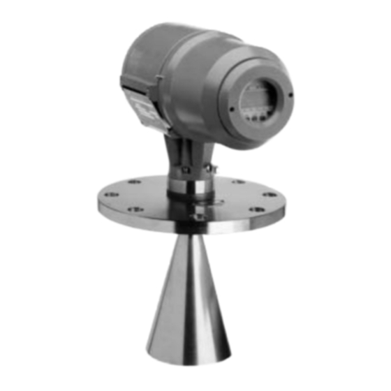
(4 - 20 mA or digital interface). The signal converter can be separated from the flange system under process conditions, without loss of pressure or escape of product. Converter Flange with micro- wave window Antenna system Installation and operating instructions BM 70 A/P Page: 7 11/00... -
Page 8: Input
When the level measuring range is exceeded (including flooding) the measured value will stick at the (adjustable) block distance (see Sect. 8.6.14). If the measured value drops below the level range, it will stay put at the set lower range limit (distance = tank height). Installation and operating instructions BM 70 A/P Page: 8 11/00... -
Page 9: Output
P Q R S T U V W X Y Z / # % & < > PC-CAT HART- Tank Inventory System HART specific software HART-Master and operating devices Point-to-point Multidrop Installation and operating instructions BM 70 A/P Page: 9 11/00... -
Page 10: Ex-E Current Output Hart
Digital input (terminals 81/82): Can be used to suspend the entire measurement procedure, i.e. measurements are "frozen" (standard setting), or to hot start the device (reprogra mming by KROHNE Service). Applicable voltage: 5...28 V DC Input resistance: > 1 kΩ... -
Page 11: Hart Communication
(conversion table), reflection, setting parameters and status. A PC can configure any BM 70 A/P via the bus (RS 485/RS232 converter required) by means of the PC-CAT program, provided no master is active. The maximum cable length - excluding amplifier - is 2000 m. - Page 12 (if necessary insert resistor 120 ohms between A and B) B) Connection of several BM 70 A/P in the RS 485 bus system via stubs to the bus cable: Bus line (2 shielded wires) Computer system RS485 connection must be terminated with 120 ohms ...
-
Page 13: Breakdown Signal
• Since signal reflections at the line ends can interfere with Communication, both the line beginning (at the computer system) and the line end (at the last device) should be terminated with the typical surge impedance of the cable (120 Ω). To do this inside the BM 70 A/P: see Section 7.9. 4.7 Breakdown signal Breakdown information can be called up via the following interfaces: •... -
Page 14: Measuring Accuracy
For that reason, all figures given in this Section 5 refer to the measured distance. BM 70 A: With antenna type 3 (139 mm / 5.47") or type 4 (200 mm / 7.87") or stilling well or Wave- Guide... -
Page 15: Repeatability
Repeatability is equal to half the value for the error of measurement. 5.4 Measured value resolution/hysteresis Measured value resolution is: 1 mm / 0.04" for BM 70 A, and 0.1 mm / 0.004" for BM 70 P Hysteresis is at least 20 times less than the error of measurement. -
Page 16: Transient Recovery Time
5.6 Turn-on drift / turn-on characteristics A rough measured value is initially displayed about 1 minute after the BM 70 A has been switched on. The first self-calibration is completed after about 2 minutes. Full measuring accuracy is attained after 30 minutes operating time. -
Page 17: Operating Conditions
6 Operating conditions Hazardous-duty systems • The BM 70 A/P is certified in conformity with European Standard (ATEX) for use in Zone 0, 1 and 2 hazardous locations. • The BM 70 A/P also has FM Approval (Factory Mutual) for CLASS I, DIV 1, GROUPS B,C,D;... - Page 18 BM 70 P : > 1/5 x H wall: min. measurable level Lower measuring range limited Several BM 70 A/P can be operated when tank has tapered bottom. in one tank. Do not position in Do not mount dead centre Do not position...
- Page 19 Length l* Type 4 200 mm (8”) 335 mm (13.2”) Type 3 140 mm (5.5”) 223 mm (8.8”) Hastelloy: + 30 mm (1.2”) (subject to change without notice) Tank nozzle Installation and operating instructions BM 70 A/P Page: 19 11/00...
- Page 20 (not for versions made of titanium or tantalum). The antenna extension should be about 100 mm (3.94") longer than the height of the fitting. Antenna extension Tank nozzle Installation and operating instructions BM 70 A/P Page: 20 11/00...
- Page 21 + 0.1 mm (0.004"). • For the BM 70 P the antenna types 1s, 2s, 3s or 4s have to be used to achieve a high measuring accuracy. Installation and operating instructions BM 70 A/P Page: 21 11/00...
- Page 22 The "Wave-Guide" is a pipe with an outside diameter of 30 mm (1.18") and an inside diameter of 25 mm (0.98"), that is bolted direct to the BM 70 A flange system (in the same way as an antenna extension). It functions like a stilling well and can be used for clean products. The Wave-Guide is not practical in conjunction with the BM 70 P as it will not provide high measuring accuracy.
- Page 23 Point 1 above is not exceeded 6.1.8 Ultimate installation on the tank • After carefully positioning the BM 70 A/P on the tank fitting flange (not forgetting the gasket), align the BM 70 A/P and the gasket.
- Page 24 20 mm. The sunshade is easily fitted/dismantled with the aid of 4 screws S (included). An Allen key (size 4 mm) is required. Dimensions in mm (inches) Installation and operating instructions BM 70 A/P Page: 24 11/00...
-
Page 25: Ambient Conditions
6.2 Ambient conditions 6.2.1 Hazardous locations BM 70 A/P Ex is suitable for use in hazardous locations of the following zones: 0, 1, 2 Temperature classes: T6...T2; danger groups: IIA...IIC For further information: see Section 10. 6.2.2 Ambient temperature of signal converter BM 70 A/P with horn antenna or Wave-Guide: -20 ... -
Page 26: Product Conditions
Dielectric Constant and Reflection Factor ε Benzene Phosgene Phenol Sulfuric acid Glycol Water Paraffin Toluene Methanol Nitrobenzene Petrol Sulfur Chlorine U S E A B L E R A N G E Installation and operating instructions BM 70 A/P Page: 26 11/00... -
Page 27: Maintenance
Teflon plug at the waveguide window (see Section 7.4 "Field assembly of the BM 70 A/P"). If cleaning agents are used, take material resistance into account! Installation and operating instructions BM 70 A/P... -
Page 28: Design
7 Design Hazardous-duty systems The BM 70 A/P-Ex is approved to European Standard EN 50014/18/19/20 for use in hazardous locations of Zones 0, 1 and 2. • Electronics compartment: Flameproof Enclosure "d" • Terminal compartment: Increased Safety "e" for signal output and power supply Optionally: Intrinsic Safety "i"... -
Page 29: Dimensions And Weights
138 (5.43) 17 (37.5) DIN 11851 (dairy) DN 100 / ANSI 4" 158 (6.22) 18 (39.7) DN 50, DN 65, DN 80 DN 150 / ANSI 6" 216 (8.5) 23 (50.7) Installation and operating instructions BM 70 A/P Page: 29 11/00... -
Page 30: Replacement Of The Signal Converter
Ensure that the screw thread of the covers on the terminal and electronic compartments is well greased at all times. 7.4 Field assembly • When the BM 70 A/P needs to be field assembled, all signal converter required parts are included with the supply... -
Page 31: Selection Of Antenna Type And Size
7.5 Selection of antenna type and size This BM 70 A recommendation for the optimum application range is based on application experience and designed to minimize potential problems. If the recommended antenna is unacceptable, any other configuration may also be tested. -
Page 32: Materials Of Construction
Aluminium with electrostatic powder coating to DIN 55990-3. Sight window: Glass 7.6.2 Flange system (Antenna, extensions and flange or flange plating) Available materials for BM 70 A/P flange systems (in contact with the product): DIN No. AISI equivalent Versions mit horn antenna or Wave-Guide: Stainless steel 1.4571... -
Page 33: Electrical Connection
(Ex-e) of the signal converter. Observe requirements specified in VDE 165, and consult the safety advice given in Section 9.4. In the BM 70 A/P version with intrinsically safe signal output, only certified intrinsically safe equipment may be connected to the blue terminals, even if the device is not operated in the... -
Page 34: Terminating Resistor For The Rs 485 Interface
120 Ω at the RS 485 output board connections A and B. For this purpose, the housing (flameproof enclosure) of the BM 70 A/P signal con- high- verter needs to be opened (see Sect. 9.3) and the Ω... -
Page 35: User Interface
8.1 Local display In the versions with local display at the BM 70 A/P signal converter, configuration can be carried out directly at the device. If a local display is not featured, the PC-CAT program (see Sect. 8.12) must be used to change the parameter setting (assuming a communicable interface is provided). -
Page 36: Function Of The Keys
"START" message is shown until a measured value is determined. If instead you wish to return to Configuration, press the ↑ key first until "RETURN" is displayed, and then the ↵ key. Installation and operating instructions BM 70 A/P Page: 36 11/00... -
Page 37: Operator Control Concept
If after pressing a key "NO ACCESS" is displayed, this means that the keypad is temporarily blocked owing to a configuration access via the signal output. The keys are available again after Communication has finished. Installation and operating instructions BM 70 A/P Page: 37 11/00... - Page 38 6 3 7 0 6 3 7 0 → To revert to function display 6 3 7 0 3.1.1. ↵ T A N K H E I G H T Installation and operating instructions BM 70 A/P Page: 38 11/00...
- Page 39 3.1.3 ANTENNA Options STANDARD STANDARD * Selection of the antenna type. WAVE STICK (WAVE STICK only for BM 70 A) 3.1.4 ANT.EXTENS. Enter 0.00 m * To input the length of the antenna extension. 0.00 [m] ... Tank height 3.1.5 DIST.PIECE...
- Page 40 (For Fct. 3.3.7 = PROFIBUS-PA or F.FOUND.: deviating input range) ® ® Options HART 3.3.7 PROTOCOL HART Select the Communications protocol. KROHNE/PC (MODBUS) (PROFIBUS-PA) (only when appropriate (F.FOUND.) hardware provided) Installation and operating instructions BM 70 A/P Page: 40 11/00...
- Page 41 RECORD 3.5.3 TIMECONST. Value Input of the time constant for measured-value filtering 1 ... 100 [s] (BM 70 A) 10 s (BM 70 A) (low-pass). 10 ... 100 [s] (BM 70 P) 30 s (BM 70 P) 3.5.4 TRACING.VEL.
-
Page 42: Configuration Examples
I for level, and switching output S for error messages. The value for Scaling 20 mA should not be greater than the response threshold. Installation and operating instructions BM 70 A/P Page: 42 11/00... - Page 43 • In order to be able to measure volume with volume measurement will depend on the the BM 70 A/P, a conversion table (volume number of set "level/volume pairs". The table) needs to be compiled with the PC- maximum number of pairs (points) that can CAT program (see Sect.
-
Page 44: Description Of Functions
(Fct. 3.2.4) can be defined as a unit under Fct. 3.2.4. Internally, this "user unit" is treated in the conversion in the same way as " m³ ". Examples of application and setting: see Sect. 8.5 Installation and operating instructions BM 70 A/P Page: 44 11/00... - Page 45 This setting may only be changed when a longer or shorter antenna extension is installed. Otherwise faulty measure- Distance between the top edge of the tank fitting and ments may result because the BM 70 A/P allows for this the lower reference point. length when measuring. After changing any antenna •...
- Page 46 Tank height = 6 m Reference offset = + 1 m Tank bottom offset = 0 The possible measuring range is: Distance = (1 m + block distance) to 7 m. Installation and operating instructions BM 70 A/P Page: 46 11/00...
- Page 47 = 20 mA is 1...100. messages. The value set here must be greater than that of Fct. 3.3.3, otherwise error during Parameter Check. Application and setting examples: see Sect. 8.5 Installation and operating instructions BM 70 A/P Page: 47 11/00...
- Page 48 This function defines the transmission rate for RS 485 PROFIBUS-PA capability are available on the market. The Communication. BM 70 A/P is easy to connect to such bus systems; it has • 1200 Bd. • 2400 Bd. • 4800 Bd.
- Page 49 8.6.11 Auto tank height FCT. 3.5.1 AUTO TANKH. With this function the height of the tank can be determined by the BM 70 A/P itself, provided the following conditions are met: • The tank has been completely drained for at least 2 minutes.
- Page 50 (reflections) that can result in incorrect measurements. → If "9 underscores" now shown, • To enable the BM 70 A/P to identify and blank out such key in the 9-keystroke Entry Code 1. interference signals, the tank profile (empty spectrum) OPERATION ↑...
- Page 51 It is recommended to maintain a safe distance of 20 to 30 cm (8" to 12") to the actual distance. location of the BM 70 A/P so as to prevent the occurrence Subsequently press key ↵ to start recording of the empty- of multiple reflections in the first place, or at least to diminish the strength of the multiple reflections (see Sect.
- Page 52 Description The parameter EPSILON R (Fct. 3.5.8) must be as exact as possible. • The BM 70 A/P firmware includes an additional function for measuring in tanks with poorly reflecting Fct. 3.5.8 EPSILON R (i.e. relative permittivity ε ↑ 3) yet non-absorbing products.
- Page 53 • Setting CONVERSION under Fct. 3.6.1: Unit same as in Fct. 3.2.3 UNIT.CONV. • Setting REFLECTION under Fct. 3.6.1: Setting range: 0...100. Examples of application and setting see Sect. 8.5 Installation and operating instructions BM 70 A/P Page: 53 11/00...
- Page 54 - Contact closes when REFLECTION lower limit exceeded e.g. operation indicator Contact closed when no * no * no * supply power applied and open at power fail Installation and operating instructions BM 70 A/P Page: 54 11/00...
-
Page 55: Functional Checks
Terminate the test by pressing the ↵ key, and the 8.7.2 Hardware test actual measured value is again present at the current Testing of the BM 70 A/P hardware can be initiated as output. required with these functions when the device is operating. -
Page 56: Pointers And Error Messages During Measurements
Minor errors, indicating the failure of functions that usually do not affect measurement, see "Error List" in Sect. 8.8.3. d) Correctable errors, which can be remedied by operator action (manual) at the BM 70 A/P, or possibly by KROHNE Service, see "Error List" in Sect. 8.8.3. - Page 57 8.8.5 Error list All errors are stored in an Error List in the BM 70 A/P. The errors are retained in this list until: 1. the cause(s) of the error(s) has been eliminated and 2. the error has been acknowledged. Errors that have been acknowledged but whose cause has not been eliminated are retained in the Error List.
-
Page 58: Messages On Start-Up
8.9 Messages on start-up When the BM 70 A/P is powered it will take about 1 minute before the first measured value is displayed (see also Sect. 5.6). During this time the following flashing messages appear in sequence in the display: STARTUP - READY - START. - Page 59 ON. Display and signal output indicate Tank with dished bottom: tank is Drain tank or switch the BM 70 A/P off more than 20% full, the BM 70 A/P for a short while. If unsuccessful, "zero" measured value, marker 5 is mistakenly located in the "tank...
- Page 60 (marker 6 is ON), measurement suspended (frozen), see Sect. 4.8. Change position of the BM 70 A/P. For DA11 Display and signal output indicate Storage tank: BM 70 A/P mounted recommended distance from tank wall, sizeable step changes in the centrically or on dome (manhole see Sect.
-
Page 61: Calculation Of The Measured Value
- Test reveals faults: switching output defective. Consult KROHNE Service or replace BM 70 A/P signal converter as described in Sect. 7.3. 8.11 Calculation of the measured value The following describes how the individual items of information are calculated from the measured distance:... -
Page 62: User Program Pc-Cat For Windows
• Trend and evaluation of the signal during operation PC-CAT works on all IBM-compatible PC’s using Windows 9x or NT. PC-CAT Version 4.00 and higher can communicate with all current KROHNE level radar gauges ® including BM 70 A/P, BM 700, BM 702 versions, also with HART protocol and RS 485. -
Page 63: Power Supply
1. Unscrew sunshade SD, if fitted. 2. Detach safety lock SV using Allen key (size 4 mm). 3. Remove cover DE from the electronic compartment (flameproof enclosure) with the supplied special wrench. Installation and operating instructions BM 70 A/P Page: 63 11/00... -
Page 64: Advice On Safety
Type BM 70 A/P level gauges do not feature any device for switching or disconnection. Class of protection The BM 70 A/P level gauge is designed for Safety Class 1 in conformity with VDE 0106 Part 1. Installation and operating instructions BM 70 A/P... - Page 65 • Electrical connection to be in conformity with VDE 0165, Section 5.6, or equivalent national regulations. • Before making the electrical connection, make sure all cables leading into the BM 70 A/P-Ex are disconnected from supply! • When used in hazardous locations, the BM 70 A/P-Ex must, in conformity with VDE 0165, be incorporated in the PA equipotential bonding system, irrespective of the type of power supply.
-
Page 66: Certificates And Approvals
10.2 Other approvals and certificates Type Company Date/Certificate No. Radio approval Vfg1117/1989; Vfg241/1995 Radio Licence JH5BM70 Preliminary approval to German pressure vessel code DruckbehV/TRB511 (flange V 96) RWTÜV No. 5636602 Installation and operating instructions BM 70 A/P Page: 66 11/00... -
Page 67: Explosion Proof Acc. To Atex
10.3 Explosion proof acc. to ATEX The instruments BM 70 A, BM 70 P and BM 700/702 are approved according to the new hazardous area directives ATEX 100a (certificate: PTB 99 ATEX 2061X). Instruments were divided up to the following Categories according to the operating range:... -
Page 68: Radio Approval
Central Approval Office for TeleCommunications (ZZF), and bear the following certification mark of the Deutsche Bundespost: "Postsignum Z G490353X" and the name of KROHNE Messtechnik GmbH & Co. KG, 4100 Duisburg, and the type designation "BM 70 Level Radar" or "BM 70-Ex Level Radar". -
Page 69: Ce Manufacturer's Declaration
D - 47058 Duisburg declare on our own responsibility that the products • BM 70 A/P Level-Radar 24V DC/AC - Ex-e current output / RS 485 • BM 70 A/P Level-Radar 115/230V AC - Ex-e current output / RS 485 to which this declaration refers, are in conformity with the following standards: •... -
Page 70: Order Information
Zone 0 Zone 1 Special items Additional calibration (BM 70 A Precision) High-precision version (BM 70 P) 90° Antenna extension ..... S-shaped antenna extension Purge connection ..... Antenna heating Others: ____________________________________________ Installation and operating instructions BM 70 A/P Page: 70 11/00... -
Page 71: External Standards, Codes And Directives
DIN 55990: 1979-12: Verification of paints and similar coating materials; Powder mould coatings ..[in German] HUG-3: HART FSK Physical Layer Specification Rev. 7.2: 1993-05 13 Quality assurance KROHNE Messtechnik GmbH & Co. KG is certified to: • DIN ISO 9001 / EN 29001 • KTA 1401 QSP 4A (nuclear power engineering) -
Page 72: Annex A: Technical Data
Reference conditions and error curves: see Sect. 5.1 and 5.2 ≤ 0.5 × error of measurement Repeatability Measured-value resolution BM 70 A: 1 mm; BM 70 P: 0.1 mm Effect of ambient temperature No significant effect on measured value(- 1 ppm/°C); (see also signal outputs) - Page 73 18-31.2 V DC or 18-26.4 V AC (45-66 Hz) 115/230 V AC optionally: 100-120 V AC (tolerance: 85-127V), 200-240 V AC (tolerance: 170-254V); 45-66 Hz Power consumption Typically 7.5 - 10 W / 12 VA Installation and operating instructions BM 70 A/P Page: 73 11/00...
-
Page 74: Annex B: Type Code / Nameplates
: Hastelloy C : Titanium : Tantalum : Monel » Gasket materials: FFKM : Kalrez™ 4079 or Parofluor™ V8545-75 K2035 : Kalrez™ 2035 K1091 : Kalrez™ 1091 : Viton™ : FEP-sheathed gasket Installation and operating instructions BM 70 A/P Page: 74 11/00... - Page 75 Baujahr Manufacturer Type acc. to Typ gemäß dem type code Typenschlüssel Seriennummer Serial number Operating/test Betriebs- / Prüfdruck Operating temperature Betriebstemperatur pressure 2061 Beschriftung nach Kundenwunsch Inscription as requestedby customer Installation and operating instructions BM 70 A/P Page: 75 11/00...
- Page 76 Operating temperature Approval information Betriebstemperatur Hersteller Year of manufacture Baujahr Zulassungsinformation Beschriftung nach Typ gemäß dem Seriennummer Inscription as requested Type acc. to Serial number by customer type code Kundenwunsch Typenschlüssel Installation and operating instructions BM 70 A/P Page: 76 11/00...
-
Page 77: Annex C: Spare Parts
Annex C: Spare parts Installation and operating instructions BM 70 A/P Page: 77 11/00... - Page 78 Installation and operating instructions BM 70 A/P Page: 78 11/00...
- Page 79 Installation and operating instructions BM 70 A/P Page: 79 11/00...
-
Page 80: Annex D: Signed Declaration To Accompany A Device Returned To Krohne
KROHNE may only handle, test and repair returned level gauges that have been in contact with liquids if it is possible to do so without risk to personnel and environment. This means that KROHNE can only service your unit if it is accompanied by a certificate in line with the following model confirming that the device is safe to handle. -
Page 81: Device Configuration
Annex E: Table on documentation of device configuration CHECK LIST PARAMETERS BM 70 A/P.Vers.:....Date: ....Device No...........: Comm. No..:..........Location............: ..............Contact person...........: Telephone......: ....... Remarks :.................................................. -
Page 82: Annex F: Index
Product conditions Fuses 9.2, 9.3 Product temperature 6.3.4, 10.3 Gaskets 6.2.3, 7.6.3 Profibus 8.6.9 ® HART 4,1, 4.4 Protection category 6.2.1, 6.2.7, 7 Hazardous-duty "Ex" 6, 6.2.1, 7, 9.3, 10 Installation and operating instructions BM 70 A/P Page: 82 11/00... - Page 83 5.5, 8.6.13 TN system Tracking speed 8.6.13 Transient recovery time Transmission angle 6.1.1 Transport Page 3 Turn-on characteristics Type code Annex B Units 8.6.1 Vessel, see Tank Vibration endurance limit 6.2.9 Installation and operating instructions BM 70 A/P Page: 83 11/00...
Need help?
Do you have a question about the BM 70 A and is the answer not in the manual?
Questions and answers