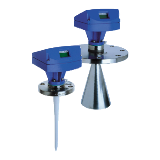
KROHNE BM 702 Installation And Operating Instruction
Level-radar
Hide thumbs
Also See for BM 702:
- Operating instructions manual (40 pages) ,
- Remote operation instructions (10 pages)
Table of Contents
Advertisement
Advertisement
Table of Contents

Subscribe to Our Youtube Channel
Related Manuals for KROHNE BM 702


Summary of Contents for KROHNE BM 702
- Page 1 © KROHNE 07/00 7.02230.31.00 Installation and operating instructions Level-Radar BM 702 Variable area flowmeters Vortex flowmeters Flow controllers Electromagnetic flowmeters Ultrasonic flowmeters Mass flowmeters Level measuring instruments Communications technology Engineering systems & solutions...
- Page 2 Report on factory settings for the signal converter • Certification and approval documents, unless reproduced in the device documentation Installation material (stud bolts, flange gasket and cabling) not supplied, to be provided by customer! Installation and operating instructions BM 702 (07/00)
-
Page 3: Table Of Contents
The BM 702 level gauge is designed solely for measuring the level, distance, volume and reflection of liquids, pastes, slurries, particulate materials and solids. The BM 702 level gauge does not form part of an overfill protection system as defined in the WHG (= German water pollution regulation). -
Page 4: Installation
Installation Most of the BM 702 versions are supplied in fully assembled condition. In this case, you may skip this chapter. However, if a device should be delivered in parts, or parts are subsequently replaced, the following should be noted. -
Page 5: Mechanical Installation
Mechanical installation Hazardous-duty systems: • The BM 702 Ex is certified in conformity with European Standard for use in Zone 0, 1 and 2 hazardous locations (dependent on version). • Attention is drawn to the data and information given on the nameplate of the converter, the nameplate of the flange and the specifications in the approval certificates. - Page 6 Tighten down stud bolt nuts firmly. The tightening torque is dependent upon the strength properties of the stud C* = shielding strip B = BM 702 flange bolts and the pressure rating of the S* = strap retainer F = tank flange...
-
Page 7: Electrical Connection
The 4-20 mA supply must be able to provide the following voltage U at the terminals of the BM 702 – dependent on the current I. Please consider also the line resistance and possible loads on the secondary side of the supply unit. -
Page 8: Setting The Parameters
Adapter ≥ 120 Ω With the program PC-CAT, version 3.01 or higher, you can configurate BM 702 instruments in a very comfortable way from a PC. Connect the non-intrinsically safe side of the isolation amplifier over a load between 120 Ω and 350 Ω to the Smart adapter (delivered together with PC-CAT) and connect it with a serial port of the PC. - Page 9 "disappear" if measurements are carried out near the bottom. The measured value is then automatically set to the level of the tank bottom. Measurement frozen: Device is in the block distance detection (see below). ? 6: Installation and operating instructions BM 702 (07/00)
- Page 10 This example was written for the case: current output = level (default). For distance measurement the points 0% (short distance = high level) and 100% (large distance = low level) are exchanged If no reliable measurement is possible „NO ACCESS“ is displayed. Abort by pressing ↵ Installation and operating instructions BM 702 (07/00)
- Page 11 (high temp. version = 120 mm). 3.1.6 STILLWELL Select NO / YES Selection: without or with still well. If “YES“: enter 25 ... 200 [mm] With still well: enter inside diameter in [mm] Installation and operating instructions BM 702 (07/00)
- Page 12 (for HART® multidrop) 3.3.7 PROTOCOL Select Select communications HART/KROHNE-PC protocol USER DATA 3.4.1 LANGUAGE Select GB-USA/D/F/I/E/P/S Select language for the optional display. 3.4.2 ENTRY CODE 1 Select NO/YES Switch the access lockout on/off. Installation and operating instructions BM 702 (07/00)
- Page 13 (only for Fct. 3.5.7) 3.5.9 TANKTYPE Select STORAGE T./ Select tank type. PROC TANK STORAGE T. = smooth product surface PROC TANK = slightly disturbed product surface The default settings are marked in the table bold. Installation and operating instructions BM 702 (07/00)
- Page 14 The bottom reference point is that “point“ in the tank on which the microwaves of the BM 702 hit and from which they are reflected. This may be the tank bottom (symmetrical tank with flat bottom) or the non-horizontal part of the bottom (e.g.
- Page 15 Empty-tank spectrum To enable the BM 702 to identify and blank out interference signals, e.g. caused by fixed and moving tank internals, the tank profile (empty-tank spectrum) needs to be recorded once only prior to (initial) start-up. For recording, the tank should be completely empty and all moving parts (e.g.
- Page 16 Fct. 3.5.1. Conversion table/Volume table A table consisting of a maximum of 50 points can be stored in the BM 702 for non-linear or linear conversion of the level, e.g. into a volumetric value. This table, however, can only be programmed with the PC-CAT program (Fct.
- Page 17 TANK TYPE Display of default value → PROC TANK ↑ ↑ Select tank type "storage tank" STORAGE T. Return to measurement function with PARAM.CHECK, 5x↵ confirmation of changed parameters then START, then meas.val. display Installation and operating instructions BM 702 (07/00)
-
Page 18: Maintenance, Error Handling
Maintenance, error handling Replacement of the signal converter Before commencing, note the parameters of the BM 702 and switch off the power supply! Disconnect all cables from the terminals in the terminal compartment. Remove the 4 Allen screws M (Allen key size 5 mm) and lift off the signal converter. -
Page 19: Safety Information
Safety information Hazardous-duty systems • Types of protection in the BM 702 terminal compartment: Intrinsically safe"ia" • Consult the relevant wiring and installation regulations, e.g. VDE 0165, before mounting, dismantling or making electrical connections in a hazardous area Temperature rating of connecting cables:... -
Page 20: Technical Data (Extract)
PN 64 inches psig psig psig psig Wave-Stick: max. 16 bar / 232 psig, temperature-dependent: [psig] [bar] +232 46 - 0.3·T[°C] bar 745 - 2.42·T[°F] psig pressure temperature T +100 +150 +212 +302°F Installation and operating instructions BM 702 (07/00) - Page 21 (delivered with 1 cable gland M 20 mm or ® QUICKON 2-pole cutter clamp) Terminals: Cable cross-section 0.5-1.5 mm² (AWG 20-16) U-clamp terminals (for PA and FE) cable cross-section max. 4 mm² (AWG 12) Installation and operating instructions BM 702 (07/00)
-
Page 22: Bm 702 Level-Radar Type Code
Flange plating and antenna of Hastelloy C (e.g. C4 or C22) used material: see marking on plating Flange plating and antenna of Titanium Flange plating and antenna of Tantalum Flange plating and antenna of Monel » gasket material: Installation and operating instructions BM 702 (07/00) - Page 23 -40°C (-40°F) ––– +130°C (+266°F) +150°C (+302°F) WS SS PTFE -20°C (-4°F) ––– +130°C (+266°F) +150°C (+302°F) WS SS PP -20°C (-4°F) ––– +100°C (+212°F) +100°C (+212°F) -20°C (-4°F) ––– +130°C (+266°F) ––– Installation and operating instructions BM 702 (07/00)
-
Page 24: Parameter Check List
Multiple reflections (yes/no)....: ....: ....: ....: 3.5.6 Block distance ident (yes/no)....: ....: ....: ....: 3.5.7 Function FTB ........: ....: ....: ....: 3.5.8 Epsilon R..........: ....: ....: ....: 3.5.9 Tank type..........: ....: ....: ....: Installation and operating instructions BM 702 (07/00)
Need help?
Do you have a question about the BM 702 and is the answer not in the manual?
Questions and answers