
Related Manuals for Phoenix Contact IPCH-4X-PCL-TCP-24DC-UT


Summary of Contents for Phoenix Contact IPCH-4X-PCL-TCP-24DC-UT
- Page 1 Starting up and operating the IPCH-4X-PCL-TCP-24DC-UT ImpulseCheck module User manual...
- Page 2 Starting up and operating the IPCH-4X-PCL-TCP-24DC-UT ImpulseCheck module UM EN ImpulseCheck, Revision 00 2019-04-25 This user manual is valid for: Designation Revision Order No. IPCH-4X-PCL-TCP-24DC-UT 1045379 PHOENIX CONTACT GmbH & Co. KG • Flachsmarktstraße 8 • 32825 Blomberg • Germany phoenixcontact.com...
-
Page 3: Table Of Contents
Data interfaces ....................25 3.9.1 Ethernet ....................25 Mounting and connecting hardware ..................27 Safety notes......................27 Mounting the ImpulseCheck module ..............28 Connecting the cables ..................29 4.3.1 Sizing of the power supply ..............30 Connecting the remote signaling .................31 3 / 82 108774_en_00 PHOENIX CONTACT... - Page 4 IPCH-4X-PCL-TCP-24DC-UT Connecting Ethernet....................31 Connecting sensors.....................32 4.6.1 Assignment of the sensors ..............33 Web-based management (WBM) ....................35 Establishing a connection to the WBM ..............35 WBM page construction ..................36 Navigation area ....................37 Data area ......................38 5.4.1 “Information” page of the ImpulseCheck module ........38 5.4.2...
- Page 5 Table of contents Ordering data and technical data .....................71 Ordering data.......................71 Technical data .....................72 Technical appendix........................75 Extended temperature range ................75 Appendix for document lists......................76 List of figures .......................76 List of tables ......................78 Index........................79 5 / 82 108774_en_00 PHOENIX CONTACT...
- Page 6 IPCH-4X-PCL-TCP-24DC-UT 6 / 82 PHOENIX CONTACT 108774_en_00...
-
Page 7: For Your Safety
– Qualified application programmers and software engineers. The users must be familiar with the relevant safety concepts of automation technology as well as applicable stan- dards and other regulations. 7 / 82 108774_en_00 PHOENIX CONTACT... -
Page 8: Field Of Application Of The Product
IPCH-4X-PCL-TCP-24DC-UT Field of application of the product 1.3.1 Intended use The ImpulseCheck module is an assistance system for collecting measured data of over- voltage events. The collected measured data is sent to the PROFICLOUD. The measured data is evaluated in the PROFICLOUD and the status of the connected surge protection is displayed on the ImpulseCheck module. - Page 9 On first request, you shall release Phoenix Contact and the companies associated with Phoenix Contact GmbH & Co. KG, Flachsmarktstrasse 8, 32825 Blomberg in accordance with §§15ff.AktG (German Stock Corporation Act), hereinafter collectively referred to as “Phoenix Contact”, from all third-party claims made due to improper use.
- Page 10 IPCH-4X-PCL-TCP-24DC-UT NOTE: Device failure The device is designed for a specific ambient temperature range (see Section 9.2, “Tech- nical data”). If you operate, store or transport the device in ambient temperatures that are not within the specified range, this may lead to device failure.
-
Page 11: Transport And Unpacking
The storage location must meet the following requirements: – – Protected from unauthorized access – Protected from harmful environmental influences such as UV light – Temperature range: -35°C ... +85°C – Permissible humidity: 30% ... 95% (non-condensing) 11 / 82 108774_en_00 PHOENIX CONTACT... -
Page 12: Checking The Delivery
Damaged packaging is an indicator of potential damage to the device that may have oc- curred during transport. This could result in a malfunction. • Submit claims for any transport damage immediately, and inform Phoenix Contact or your supplier as well as the shipping company without delay. •... -
Page 13: Description Of The Impulsecheck Module
For this, the hardware must be configured accordingly in the PROFICLOUD after installa- tion. Only then will you receive a meaningful evaluation of the statuses of the SPDs con- nected to the ImpulseCheck module. 13 / 82 108774_en_00 PHOENIX CONTACT... -
Page 14: Licensing Information On Open Source Software
IPCH-4X-PCL-TCP-24DC-UT For an optimum monitoring of your SPDs, the remote indication contact of the SPD has to be connected to the ImpulseCheck module. The ImpulseCheck module features a two-po- sition connection for the remote indication contact, which is used to connect the N/C contact or the N/O contact of the SPD. -
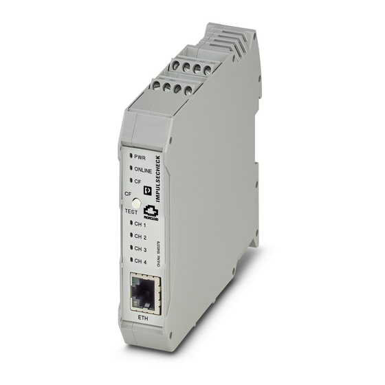
Page 15: Components Of The Impulsecheck Module
Remote signaling connection from the SPD Diagnostic and status indicators Status and configuration button Ethernet interface for connection to the local network and the PROFICLOUD Sensor connections 1 ... 4 Sensor connections 5 ... 8 15 / 82 108774_en_00 PHOENIX CONTACT... -
Page 16: Printing
IPCH-4X-PCL-TCP-24DC-UT 3.3.2 Printing IPCH-4X-PCL-TCP-24DC-UT 10 453 79 PHOENIX CONTACT GmbH&Co.KG Flachsmarktstr. 8 V/C : 00 32825 Blomberg, Germany Date : L-058 Sensor connection Sensor Terminal point conductor coloring CH 1 CH 2 CH 3 CH 4 Brown White Serial No. -
Page 17: Diagnostic And Status Indicators
PROFICLOUD is being established. Connection to the PROFICLOUD established. Configuration mode disabled, internal web server disabled. Configuration mode enabled, Green Configuration internal web server enabled. Flashing Confirmation of reset of network configuration. (3x) 17 / 82 108774_en_00 PHOENIX CONTACT... - Page 18 IPCH-4X-PCL-TCP-24DC-UT Table 3-1 Diagnostic and status indicators of the ImpulseCheck module Desig- Color Indication State Description nation Channel not configured in the PROFICLOUD Status indicator Green/yel no connection to the PROFICLOUD measuring chan- low/red nel 1, 2, 3, 4 state unknown.
-
Page 19: Status And Configuration Button
During operation, press the status and configuration button for > 1 s ... < 10 s. figuration mode The ImpulseCheck module is put into configuration mode (see Section 5.4.2, “ImpulseCheck module “Configuration” page”). The configuration mode is automatically terminated after 30 minutes of inactivity. 19 / 82 108774_en_00 PHOENIX CONTACT... - Page 20 IPCH-4X-PCL-TCP-24DC-UT Table 3-2 Actuating the status and configuration button Designation Indication Actuation Description Current status of the monitored SPD is being retrieved from the PROFICLOUD. Test mode < 1 s The update is acknowledged by the status indicators (CH 1 ... CH 4) of the ImpulseCheck module flashing.
-
Page 21: Parameterization Memory
CH1...4 ONLINE TEST/CF SENSOR 1...4 (SPD) 3,3V T-BUS 24V DC Figure 3-5 Internal basic circuit diagram Key: μC μC Microprocessor Transmitter Remote signaling from the RJ45 interface Voltage transformer Status and configuration but- Sensor 21 / 82 108774_en_00 PHOENIX CONTACT... -
Page 22: Connections
IPCH-4X-PCL-TCP-24DC-UT Connections 3.8.1 24 V supply connection 0V 0V +24V+24V L I N Figure 3-6 24 V supply connection Table 3-3 Terminal point assignment of the supply connection Terminal Assignment Description point Reference potential GND (24 V supply) Reference potential GND (24 V supply) -
Page 23: Remote Signaling Connection From The Spd
Remote signaling connection from the SPD Table 3-4 Terminal point assignment of the remote signaling Terminal point Description Not used Not used FM 12 or FM 14 from the SPD FM 11 from the SPD 23 / 82 108774_en_00 PHOENIX CONTACT... -
Page 24: Connection Of Sensor Cables
IPCH-4X-PCL-TCP-24DC-UT 3.8.3 Connection of sensor cables The sensors (IPCH-SC-...) necessary for measuring are available separately. The sen- sors are to be found in the product accessories area at phoenixcontact.net/product/1045379. L I N Figure 3-8 Connection of sensor cables Table 3-5... -
Page 25: Data Interfaces
Pin 6 Receive data - Pin 7 – – – – Pin 8 Figure 3-9 Ethernet interface and pin assignment The Ethernet interface is able to switch over the transmitter and receiver automatically (auto crossover). 25 / 82 108774_en_00 PHOENIX CONTACT... - Page 26 IPCH-4X-PCL-TCP-24DC-UT 26 / 82 PHOENIX CONTACT 108774_en_00...
-
Page 27: Mounting And Connecting Hardware
The device is automatically grounded (FE) when it is snapped onto a grounded DIN rail. There is an FE spring on the rear of the device. This spring creates the contact to the DIN rail when the device is placed on the DIN rail. 27 / 82 108774_en_00 PHOENIX CONTACT... -
Page 28: Mounting The Impulsecheck Module
IPCH-4X-PCL-TCP-24DC-UT Mounting the ImpulseCheck module • Disconnect the unit from the power supply. • Place the device onto the DIN rail from above (A), then press it down (B). Figure 4-1 Mounting the ImpulseCheck module The device is automatically grounded (FE) when it is snapped onto a grounded DIN rail. -
Page 29: Connecting The Cables
Tighten the clamping pocket screw using the screwdriver (B). Connection torque: 0.5 Nm ... 0.6 Nm Figure 4-2 Connecting cables Recommended: Bladed screwdriver, blade width 2.5 mm (e.g., SZS 0,4x2,5 VDE, Order No. 1205037) 29 / 82 108774_en_00 PHOENIX CONTACT... -
Page 30: Sizing Of The Power Supply
IPCH-4X-PCL-TCP-24DC-UT 4.3.1 Sizing of the power supply • Select an appropriate power adapter. WARNING: Loss of electrical safety when using unsuitable power supplies The device is intended exclusively for operation with protective extra-low voltage (PELV) in acc. with EN 60204-1. Only PELV in accordance with the listed standard may be used for the supply. -
Page 31: Connecting The Remote Signaling
Use an Ethernet cable that complies with at least CAT5 of IEEE 802.3. • Observe the bending radii of the Ethernet cables used. • Connect the Ethernet cable to the “ETH” RJ45 socket. Figure 4-5 Connecting Ethernet 31 / 82 108774_en_00 PHOENIX CONTACT... -
Page 32: Connecting Sensors
IPCH-4X-PCL-TCP-24DC-UT Connecting sensors The sensors (IPCH-SC-...) necessary for measuring are available separately. The sen- sors are to be found in the product accessories area of this user manual (see Section 9.1) or in the product accessories area at phoenixcontact.net/product/1045379. The sensor has recesses (radii) on two opposing sides. The two differently sized recesses are for positioning on the connecting cables. -
Page 33: Assignment Of The Sensors
Not connected PE/PEN* PE/PEN* PE/PEN* * With SPD configurations with a virtual star point (e.g., 2+F, 3+V), monitor the protective conductor with an additional sensor. Select the next highest free sensor channel for this. 33 / 82 108774_en_00 PHOENIX CONTACT... - Page 34 IPCH-4X-PCL-TCP-24DC-UT 34 / 82 PHOENIX CONTACT 108774_en_00...
-
Page 35: Web-Based Management (Wbm)
“IP settings”). With an active firewall, connections via the 8488 and 443 ports and to the proficloud.net do- main need to be enabled in order for the ImpulseCheck module to communicate with the PROFICLOUD. 35 / 82 108774_en_00 PHOENIX CONTACT... -
Page 36: Wbm
IPCH-4X-PCL-TCP-24DC-UT WBM page construction The WBM construction consists of two areas: – The navigation area (1), see Section 5.3 – The data area (2), see Section 5.4 Figure 5-1 WBM: page construction 36 / 82 PHOENIX CONTACT 108774_en_00... -
Page 37: Navigation Area
If you click on the symbol/figure of the device, this will guide you directly to the article page of the ImpulseCheck module in the Phoenix Contact online shop. Status of the ImpulseCheck module in the PROFICLOUD, Table 5-1 “WBM: PROFICLOUD status”... -
Page 38: Data Area
IPCH-4X-PCL-TCP-24DC-UT Data area If you call the WBM, the “Information” page opens by default. 5.4.1 “Information” page of the ImpulseCheck module On the “Information” page, all important information on the ImpulseCheck module is dis- played. With the exception of data that is to be configured individually (see Section 5.4.2,... - Page 39 Indication of the nameserver (DNS) assigned by the DHCP server. If no DHCP is used, Nameserver 1 and Nameserver 2 are used. Nameserver 1 Display (fall-back) Nameserver 1, configurable Nameserver 2 Display (fall-back) Nameserver 2, configurable 39 / 82 108774_en_00 PHOENIX CONTACT...
- Page 40 IPCH-4X-PCL-TCP-24DC-UT PROFICLOUD All information on the status of the ImpulseCheck module in connection with the PROFICLOUD can be found in the “PROFICLOUD” area. Table 5-1 WBM: PROFICLOUD status UUID Unique number (UUID) of the connected module Each ImpulseCheck module has a UUID assigned by the manufacturer. Via this UUID, the ImpulseCheck module can be clearly identified and integrated into the PROFICLOUD.
- Page 41 • Register the module via the module UUID or via the link in the WBM in a PROFICLOUD account. “Unknown” The state is unknown. • Check if the device is connected to the PROFICLOUD. 41 / 82 108774_en_00 PHOENIX CONTACT...
-
Page 42: Impulsecheck Module "Configuration" Page
IPCH-4X-PCL-TCP-24DC-UT 5.4.2 ImpulseCheck module “Configuration” page Unlike on the “Information” page, the data displayed on the “Configuration” page can be adapted. The system identification files are directly synchronized with PROFICLOUD and can be configured in the WBM and in PROFICLOUD. - Page 43 If there is no connection to the network, the IP address be- comes available and can be assigned again. The static or fall-back information is set by default. Figure 5-5 WBM: static or fall-back IP configuration 43 / 82 108774_en_00 PHOENIX CONTACT...
-
Page 44: Wbm: "Use Http Proxy" Drop-Down Menu
IPCH-4X-PCL-TCP-24DC-UT Proxy settings In the “Proxy Settings” area, you can specify if an HTTP proxy server is to be used for Inter- net access. Figure 5-6 WBM: “Use HTTP Proxy” drop-down menu It an HTTP proxy server is used, select “Yes” from the “Use HTTP Proxy” drop-down menu. -
Page 45: Impulsecheck Module Page "Firmware Update
Start the Installation via the “Upload and Reboot” button. The ImpulseCheck module implements a reset. The success or failure of the update is indicated on the “Firmware Update” page. Figure 5-8 WBM: Firmware update 45 / 82 108774_en_00 PHOENIX CONTACT... - Page 46 IPCH-4X-PCL-TCP-24DC-UT 46 / 82 PHOENIX CONTACT 108774_en_00...
-
Page 47: Proficloud Solution "Impulseanalytics
Figure 6-1 PROFICLOUD solution “ImpulseAnalytics” If you are using the PROFICLOUD solution “ImpulseAnalytics” for the first time, you have to agree to the conditions of the data privacy statement. The “ImpulseCheck devices” page opens. 47 / 82 108774_en_00 PHOENIX CONTACT... -
Page 48: Impulsecheck Devices" Page
IPCH-4X-PCL-TCP-24DC-UT “ImpulseCheck devices” page On the “ImpulseCheck devices” page, you register new ImpulseCheck modules. Each reg- istered ImpulseCheck module is displayed with the status of the connected SPD. Click on the respective module to go to the detail view of the module (see Section 6.2.3, ““Impulse-... -
Page 49: Registering An Impulsecheck Module
The registered ImpulseCheck module is shown on the “ImpulseCheck devices” page. symbol on the “ImpulseCheck devices” page indicates that up to now no SPD has been assigned to the ImpulseCheck module and/or that the ImpulseCheck module is offline. 49 / 82 108774_en_00 PHOENIX CONTACT... -
Page 50: Assigning An Spd
IPCH-4X-PCL-TCP-24DC-UT 6.2.2 Assigning an SPD To assign the connected SPD to the ImpulseCheck module, proceed as follows: • On the “ImpulseCheck devices” page, click on the ImpulseCheck module you want to assign the SPD to. The “ImpulseCheck devices / [module name]” page opens. - Page 51 SPDs from Phoenix Contact are listed in the drop-down list. For third-party devices, note: • If you do not use an SPD from Phoenix Contact, select the entry “Custom” from the “Arrester Type” drop-down list. In the “Add Arrester” window, the “Arrester Layout” drop-down list and the “Divisions per pole”...
- Page 52 IPCH-4X-PCL-TCP-24DC-UT • From the “Unit” drop-down list, select the corresponding measurement unit (millimeters or inches). • If you use V-shaped wiring at the SPD, enable the check box “V-shaped wiring”. • If you use an SPD with remote indication contact, select the type of the connected re- mote indication contact from the “FM Contact Status”...
-
Page 53: Impulsecheck Devices / [Module Name]" Page
The “ImpulseCheck devices / [module name]” page is divided into three areas (see Figure 6-6): – “[Module name]” (1) area – “Arrester [SPD name]” (2) area – “Surge Current List/Transient Overvoltage List” (3) area Figure 6-6 “ImpulseCheck devices / [module name]” page with SPD (“Arrester”) 53 / 82 108774_en_00 PHOENIX CONTACT... - Page 54 IPCH-4X-PCL-TCP-24DC-UT “[Module name]” (1) area In the “[module name]” area, you can modify the information (name, description, installation location, contact) on the ImpulseCheck module that was entered during registration. You can also delete the ImpulseCheck module from the list of registered modules.
-
Page 55: Impulsecheck Devices / [Module Name] / Arrester" Page
• Click the “Save” button to save your entries. The modified assignment is displayed on the “ImpulseCheck devices / [module name]” page in the “Arrester: [SPD name]” area. 55 / 82 108774_en_00 PHOENIX CONTACT... -
Page 56: Example: "Impulsecheck Devices / [Module Name] / Arrester" Page, Type Of Remote Indication Contact
IPCH-4X-PCL-TCP-24DC-UT Changing the type of the To change the type of the remote indication contact, proceed as follows: remote indication contact • Click on the “Edit” button. The “Update Arrester” window opens. • From the “FM Contact Status” drop-down list, select the type of the remote indication contact. -
Page 57: Surge Current List" Tab
To show the measured data of a single connecting cable, in the key at the top right, dou- ble-click on the respective connecting cable. • To hide the measured data of a single connecting cable, in the key at the top right, click on the respective connecting cable. 57 / 82 108774_en_00 PHOENIX CONTACT... -
Page 58: Transient Overvoltage List" Tab
IPCH-4X-PCL-TCP-24DC-UT “Transient Overvoltage On the “Transient Overvoltage List” tab, the transient overvoltage events for each connect- List”: transient overvolt- ing cable at the SPD are listed. age events Figure 6-10 “Transient Overvoltage List” tab Displaying measured data Use the “Overvoltage Stats” tab to go to the “ImpulseCheck devices / [module name] / Over- graphically voltage Statistics”... - Page 59 If you move the cursor over the graphic, an additional tool bar becomes visible above the graphic. Additional functions are available via the tool bar. E.g., you can download the graphic as a PNG file or display measured values by moving the cursor over the graphic. 59 / 82 108774_en_00 PHOENIX CONTACT...
-
Page 60: Account" Menu
IPCH-4X-PCL-TCP-24DC-UT “Account” menu • To open the “Account” menu, click on the entry “Account” in the sidebar. Figure 6-12 “Account” menu Use the “Account” menu to view information on the current account, invite users to your ac- count and determine their role, and create new accounts. -
Page 61: Members [Account Name]" Page
The participating users are listed on the page with their user roles. Adding or inviting a user • To add or invite a user to your account, click the “Add Member” button. to the account The “Add Account Member” window opens. 61 / 82 108774_en_00 PHOENIX CONTACT... -
Page 62: Add Account Member" Window
IPCH-4X-PCL-TCP-24DC-UT Figure 6-15 “Add Account Member” window • If you want to add a user to your account who is already registered in the PROFICLOUD, enter the user name in the “Enter Member's Username or Email” input field. • If you want to invite a new user to your account, enter the e-mail address of the person to be invited in the “Enter Member's Username or Email”... -
Page 63: Add Account" Page
To switch between several accounts, click on your user name on the top right of the counts page. The drop-down menu for account switch and logout opens. Figure 6-17 Drop-down menu for account switch and logout • From the drop-down list with the symbol, select the desired account. 63 / 82 108774_en_00 PHOENIX CONTACT... -
Page 64: Journal" Menu
IPCH-4X-PCL-TCP-24DC-UT “Journal” menu • To open the “Journal” menu, click on the entry “Journal” in the sidebar. Figure 6-18 “Journal” menu Use the “Journal” menu to view the history of an account and make notification settings. 6.4.1 “Journal for Account” page Figure 6-19 “Journal for Account: [account name]”... -
Page 65: Notifications Configuration" Page
A triggering instance can be an ImpulseCheck module, an account or a user. Depending on the instance type, the possible notification events are displayed in the list in the bottom area. 65 / 82 108774_en_00 PHOENIX CONTACT... - Page 66 IPCH-4X-PCL-TCP-24DC-UT • To select a notification event, click on the button in the line of the event. The “Create notification configuration” window opens. • Enable the “Email” check box and click the “Save” button. The column “Reaction Types” indicates if a notification was specified for an event. Use the button to delete notifications for the event.
-
Page 67: Removing Hardware
Open the clamping pocket (A) using the screwdriver. • Remove the cable (B). Figure 7-1 Removing the cable Removing the Ethernet connector • Release the RJ45 connector by pressing on the snap-in latch and remove the connec- tor. 67 / 82 108774_en_00 PHOENIX CONTACT... -
Page 68: Removing The Impulsecheck Module
IPCH-4X-PCL-TCP-24DC-UT Removing the ImpulseCheck module • Insert a tool in the base latch and pull gently upwards (A). Pull the device from the DIN rail (B). Figure 7-2 Removing the ImpulseCheck module 68 / 82 PHOENIX CONTACT 108774_en_00... -
Page 69: After Use
Device failure and repair Repairs may only be carried out by Phoenix Contact. • Send faulty devices back to Phoenix Contact for repairs or to receive a replacement de- vice. • We strongly recommend using the original packaging to return the product. -
Page 70: Disposal
Return for disposal As an alternative to disposal, you can return the device to Phoenix Contact. • Include a note in the packaging indicating that the device should be disposed of. -
Page 71: Ordering Data And Technical Data
Order No. Pcs./Pkt. Evaluation unit for the real-time recording of surge cur- IPCH-4X-PCL-TCP-24DC-UT 1045379 rents and transient overvoltages. Connection of up to four external sensor lines and a floating remote indication con- tact. Communication of the measurement data to the PROFICLOUD via Ethernet. -
Page 72: Technical Data
IPCH-4X-PCL-TCP-24DC-UT Technical data Dimensions (nominal sizes in mm) 22,5 114,5 ONLINE TEST PROFICLOUD CH 1 CH 2 CH 3 CH 4 Width 22.5 mm Height 104.7 mm Depth 114.5 mm Horizontal pitch 1.3 Div. General data Standards/specifications EN 61000-6-2 EN 61000-6-3 Type DIN rail module, one-piece ... - Page 73 Using terminal points to query the remote indication contact requires basic insulation in the SPD between the remote indication circuit and active conductors. This is ensured for SPDs from Phoenix Contact. Additional descriptions Note The product was successfully tested in an extended temperature range of -35 °C +85 °C.
- Page 74 IPCH-4X-PCL-TCP-24DC-UT Conformance with EMC Directive 2014/30/EU Noise immunity test in accordance with EN 61000-6-2 Electrostatic discharge (ESD) EN 61000-4-2/ Criterion B, 6 kV contact discharge, 8 kV air discharge IEC 61000-4-2 Electromagnetic fields EN 61000-4-3/IEC 61000-4-3 Criterion A, Field intensity: 10 V/m Fast transients (burst) EN 61000-4-4/IEC 61000-4-4 Criterion A, 2.2 kV...
-
Page 75: A Technical Appendix
The ImpulseCheck module was operated with a maximum of 24.5 V (ensured by using electronically regulated power supply units). – Connection of up to four sensors – Remote signaling connection from the SPD Figure A-1 Extreme ambient conditions: temperature curve 75 / 82 108774_en_00 PHOENIX CONTACT... -
Page 76: B Appendix For Document Lists
IPCH-4X-PCL-TCP-24DC-UT B Appendix for document lists List of figures Section 3 Figure 3-1: Connection and operating elements of the ImpulseCheck module ....................15 Figure 3-2: Printing ....................16 Figure 3-3: Diagnostics and status indicators ............17 Figure 3-4: Status and configuration button ............19 Figure 3-5: Internal basic circuit diagram ..............21... - Page 77 “Journal for Account: [account name]” page ........64 Figure 6-20: “Notifications Configuration” page ............65 Section 7 Figure 7-1: Removing the cable ................67 Figure 7-2: Removing the ImpulseCheck module ..........68 Appendix A Figure A-1: Extreme ambient conditions: temperature curve .........75 77 / 82 108774_en_00 PHOENIX CONTACT...
-
Page 78: B 2 List Of Tables
IPCH-4X-PCL-TCP-24DC-UT List of tables Section 3 Table 3-1: Diagnostic and status indicators of the ImpulseCheck module ....17 Table 3-2: Actuating the status and configuration button ........20 Table 3-3: Terminal point assignment of the supply connection ......22 Table 3-4: Terminal point assignment of the remote signaling ......23 Table 3-5: Terminal point assignment of the sensor connections ......24... -
Page 79: Index
Intended use ..............8 Unpacking ..............12 Interfaces Ethernet..............25 Internal basic circuit diagram........21 “Information” page ..........38 Establishing a connection........35 Maintenance ............... 69 Modifications..............8 Montieren Cables ..............29 Mounting Safety instructions ..........27 79 / 82 108774_en_00 PHOENIX CONTACT... - Page 80 IPCH-4X-PCL-TCP-24DC-UT 80 / 82 PHOENIX CONTACT 108774_en_00...
- Page 81 The receipt of technical documentation (in particular user documentation) does not constitute any further duty on the part of Phoenix Contact to furnish information on modifications to products and/or technical documentation. You are responsible to verify the suitability and intended use of the products in your specific application, in particular with regard to observing the applicable standards and regulations.
- Page 82 Should you have any suggestions or recommendations for improvement of the contents and layout of our manuals, please send your comments to: tecdoc@phoenixcontact.com 82 / 82 PHOENIX CONTACT GmbH & Co. KG • Flachsmarktstraße 8 • 32825 Blomberg • Germany phoenixcontact.com...
- Page 84 PHOENIX CONTACT GmbH & Co. KG Flachsmarktstraße 8 32825 Blomberg, Germany Phone: +49 5235 3-00 Fax: +49 5235 3-41200 E-mail: info@phoenixcontact.com phoenixcontact.com...
Need help?
Do you have a question about the IPCH-4X-PCL-TCP-24DC-UT and is the answer not in the manual?
Questions and answers