Agilent Technologies 1260 Infinity II User Manual
Flexible, infinitylab lc series
Hide thumbs
Also See for 1260 Infinity II:
- User manual (272 pages) ,
- Manual (34 pages) ,
- Installation manual (12 pages)

Related Manuals for Agilent Technologies 1260 Infinity II


Summary of Contents for Agilent Technologies 1260 Infinity II
- Page 1 Agilent InfinityLab LC Series 1260 Infinity II Flexible Pump User Manual Agilent Technologies...
- Page 2 (June 1987) or any equivalent agency regu- lation or contract clause. Use, duplication or disclosure of Software is subject to Agi- lent Technologies’ standard commercial license terms, and non-DOD Departments and Agencies of the U.S. Government will 1260 Infinity II Flexible Pump User Manual...
- Page 3 This chapter describes the meaning of error messages, and provides information on probable causes and suggested actions how to recover from error conditions. 7 Maintenance This chapter describes the maintenance of the Agilent 1260 Infinity II Flexible Pump. 1260 Infinity II Flexible Pump User Manual...
- Page 4 This chapter describes the pump in more detail on hardware and electronics. 11 LAN Configuration This chapter provides information on connecting the module to the controller software. 12 Appendix This chapter provides additional information on safety, legal and web. 1260 Infinity II Flexible Pump User Manual...
-
Page 5: Table Of Contents
Agilent Local Control Modules 4 How to Optimize the Performance of Your Module Delay Volume and Extra-Column Volume How to Configure the Optimum Delay Volume How to Achieve Higher Resolution Using Solvent Calibration Tables 1260 Infinity II Flexible Pump User Manual... - Page 6 Replace the Multi Purpose Valve Replace Parts of the Multi Purpose Valve Replace the High Pressure Outlet Filter or Filter Frit Install the Inline Filter Remove the Inline Filter Replace Parts of the Inline Filter 1260 Infinity II Flexible Pump User Manual...
- Page 7 9 Identifying Cables Cable Overview Analog Cables Remote Cables CAN/LAN Cables Agilent Module to PC USB Cables 10 Hardware Information Firmware Description Electrical Connections Interfaces Setting the 8-bit Configuration Switch Early Maintenance Feedback Instrument Layout 1260 Infinity II Flexible Pump User Manual...
- Page 8 Dynamic Host Configuration Protocol (DHCP) Link Configuration Selection Manual Configuration PC and User Interface Software Setup 12 Appendix General Safety Information Waste Electrical and Electronic Equipment Directive Radio Interference Sound Emission Agilent Technologies on Internet 1260 Infinity II Flexible Pump User Manual...
-
Page 9: Introduction
1260 Infinity II Flexible Pump User Manual Introduction Product Description Features Operating Principle Positions of the Multi Purpose Valve Leak and Waste Handling Leak Sensor Waste Concept This chapter gives an introduction to the module, instrument overview and internal connectors. -
Page 10: Product Description
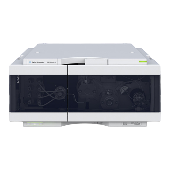
Introduction Product Description Product Description The new Agilent 1260 Infinity II Flexible Pump improves your everyday efficiency by combining the performance of a high-pressure mixing UHPLC pump with the flexibility of a low-pressure mixing UHPLC pump. The power range of 5 mL/min with a maximum pressure up to 800 bar allows to run HPLC and UHPLC methods on the same LC system. -
Page 11: Product Description
Introduction Product Description Figure 1 Overview of the Flexible Pump 1260 Infinity II Flexible Pump User Manual... -
Page 12: Features
Waters Alliance, Waters H-Class, and Shimadzu Prominence instruments. • Precise and accurate buffer/additive blending using the BlendAssist software feature, implemented in the pump driver. • Built-in active seal-wash for increased uptime. 1260 Infinity II Flexible Pump User Manual... -
Page 13: Operating Principle
A high resolution encoder unit is attached to the pump drives, which divides a single turn into 65000 steps. Each step corresponds to a volume of about 300 pL, which allows an extremely precise control. 1260 Infinity II Flexible Pump User Manual... -
Page 14: Operating Principle
Introduction Operating Principle Figure 2 The hydraulic path 1260 Infinity II Flexible Pump User Manual... -
Page 15: Positions Of The Multi Purpose Valve
Multi Purpose Valve. The flow leaves the valve through port 4 to the system (autosampler etc.). Figure 3 Valve position in normal operating mode without mixer 1260 Infinity II Flexible Pump User Manual... -
Page 16: Positions Of The Multi Purpose Valve
Introduction Positions of the Multi Purpose Valve Purge Mode In purge mode, the flow is diverted to the waste container. Figure 4 Valve position in purge mode 1260 Infinity II Flexible Pump User Manual... - Page 17 In this mode, the flow passes an optional Jet Weaver and the optional inline filter. This configuration is recommended for special applications which require an increased mixing efficiency. Figure 5 Valve position in normal operating mode with Jet Weaver 1260 Infinity II Flexible Pump User Manual...
- Page 18 7. Figure 6 Valve position in filter flush mode Damage to the valve C AU T I O N ➔ Use the filter flush mode only if the optional inline filter is installed. 1260 Infinity II Flexible Pump User Manual...
-
Page 19: Leak And Waste Handling
• from the detector's flow cell outlet • from the Multisampler needle wash port • from the Sample Cooler (condensate) • from the Seal Wash Sensor (if applicable) • from the pump's Purge Valve or Multipurpose Valve 1260 Infinity II Flexible Pump User Manual... -
Page 20: Leak And Waste Handling
Introduction Leak and Waste Handling Figure 7 Infinity II Leak Waste Concept (Flex Bench installation) 1260 Infinity II Flexible Pump User Manual... - Page 21 Introduction Leak and Waste Handling Figure 8 Infinity II Single Stack Leak Waste Concept (bench installation) 1260 Infinity II Flexible Pump User Manual...
-
Page 22: Leak Sensor
C AU T I O N The solvent DMF (dimethyl formamide) leads to corrosion of the leak sensor. The material of the leak sensor, PVDF (polyvinylidene fluoride), is incompatible with DMF. ➔ Do not use DMF. 1260 Infinity II Flexible Pump User Manual... -
Page 23: Waste Concept
1 Agilent recommends using the 6 L waste can with 1 Stay Safe cap GL45 with 4 ports (5043-1221) for optimal and safe waste disposal. If you decide to use your own waste solution, make sure that the tubes don't immerse in the liquid. 1260 Infinity II Flexible Pump User Manual... - Page 24 Introduction Leak and Waste Handling 1260 Infinity II Flexible Pump User Manual...
-
Page 25: Site Requirements And Specifications
1260 Infinity II Flexible Pump User Manual Site Requirements and Specifications Site Requirements Physical Specifications Performance Specifications This chapter provides information on environmental requirements, physical and performance specifications. Agilent Technologies... -
Page 26: Site Requirements
➔ Make sure the power connector of the instrument can be easily reached and unplugged. ➔ Provide sufficient space behind the power socket of the instrument to unplug the cable. 1260 Infinity II Flexible Pump User Manual... - Page 27 Never use the power cords that Agilent Technologies supplies with this instrument for any other equipment. ➔ Never use cables other than the ones supplied by Agilent Technologies to ensure proper functionality and compliance with safety or EMC regulations. Power cords WA R N I N G Solvents may damage electrical cables.
- Page 28 ➔ If your module was shipped in cold weather, leave it in its box and allow it to warm slowly to room temperature to avoid condensation. 1260 Infinity II Flexible Pump User Manual...
-
Page 29: Physical Specifications
Up to 4600 m (15092 ft) For storing the module Safety standards: Installation category II, Pollution degree 2 For indoor use only. IEC, EN, CSA, UL ISM Classification ISM Group 1 Class B According to CISPR 11 1260 Infinity II Flexible Pump User Manual... -
Page 30: Performance Specifications
Site Requirements and Specifications Performance Specifications Performance Specifications Table 2 Agilent 1260 Infinity II Flexible Pump (G7104C) Performance Specifications Feature Specification Comments Hydraulic system Dual pistons in series pump with proprietary servo-controlled variable stroke design and smooth motion control for active damping. -
Page 31: Performance Specifications
Site Requirements and Specifications Performance Specifications Table 2 Agilent 1260 Infinity II Flexible Pump (G7104C) Performance Specifications Feature Specification Comments Composition < 0.15 % RSD or 0.02 min SD, based on retention time at precision whichever is greater constant temperature... - Page 32 Site Requirements and Specifications Performance Specifications Table 2 Agilent 1260 Infinity II Flexible Pump (G7104C) Performance Specifications Feature Specification Comments Instrument Control LC & CE Drivers A.02.17 or above For details about supported Instrument Control Framework software versions refer to the (ICF) A.02.05 or above...
-
Page 33: Using The Module
Setting up the Pump with the Instrument Control Interface Overview Instrument Configuration The Pump User Interface (Dashboard Panel) Control Settings Method Parameter Settings Agilent Local Control Modules This chapter explains the operational parameters of the Agilent 1260 Infinity II Flexible Pump. Agilent Technologies... -
Page 34: Magnets
Using the Module Magnets Magnets This stack exemplarily shows the magnets' positions in the modules. 1260 Infinity II Flexible Pump User Manual... -
Page 35: Turn On/Off
Using the Module Turn on/off Turn on/off Power switch: On Turn instrument On/Off with the control software. Power switch: Off 1260 Infinity II Flexible Pump User Manual... - Page 36 Using the Module Turn on/off 1260 Infinity II Flexible Pump User Manual...
-
Page 37: Status Indicators
5. Resident mode (blinking) - for example during update of main firmware. 6. Bootloader mode (fast blinking). Try to re-boot the module or try a cold-start. Then try a firmware update. 1260 Infinity II Flexible Pump User Manual... -
Page 38: Best Practices
• Inspect solvent filters for dirt or blockages. Clean or exchange if no flow is coming out of the solvent line when removed from the degasser inlet. 1260 Infinity II Flexible Pump User Manual... -
Page 39: Power Up / Shut-Down The Pump
• to minimize pressure ripple by dissolving air bubbles in pump heads. Condition your complete system with solvents and composition of your application (for N O T E example 50 %/50 % A/B at 0.5 mL/min). 1260 Infinity II Flexible Pump User Manual... -
Page 40: How To Deal With Solvents
• Use lower channels (A and/or D) for buffer solutions. • Regularly flush all MCGV channels with water to remove possible salt deposits. • Check compatibility of buffers and organic solvents to avoid precipitation. 1260 Infinity II Flexible Pump User Manual... -
Page 41: Optional Inline Filter
• exchange the filter frit on a regular basis. Damage to the valve C AU T I O N ➔ Use the filter flush mode only if the optional inline filter is installed. See Technote G7167-90130 for further reference. 1260 Infinity II Flexible Pump User Manual... -
Page 42: Flushing The Filter
0.3 μm ( Inline Filter Assembly (5067-5407)). This filter can be flushed using the graphical user interface or replaced as required (see “Replace Parts of the Inline Filter” on page 173). 1260 Infinity II Flexible Pump User Manual... - Page 43 • Back- flush the filter weekly, (Flush Filter in context menu figure) • Exchange the filter frit on a regular basis. ( Frit 0.3 μm for inline filter, 5/pk (5023-0271)) See Technote G4226-90131 for further reference. N O T E 1260 Infinity II Flexible Pump User Manual...
-
Page 44: Purging The Pump
The pump should never be used for priming/purging empty tubings (never let the pump N O T E run dry). Use a syringe to draw enough solvent for completely filling the tubings to the pump inlet before continuing to prime with the pump. 1260 Infinity II Flexible Pump User Manual... - Page 45 6 Observe the pressure fluctuations. The system is air free as soon as the pressure is stable. 7 Change solvents and column according to the analytical conditions and purge the system to change solvents. 1260 Infinity II Flexible Pump User Manual...
-
Page 46: Solvent Information
UHMW-PE, SST Pressure sensor Multi Purpose Valve Polyimide, SST, DLC Ultra clean tubings are available for the use with high-end MS detectors. They are also compatible to THF. Inlet Weaver, Jet Weaver, Heat Exchanger 1260 Infinity II Flexible Pump User Manual... - Page 47 When used above room temperature, PEEK is sensitive to bases and various organic solvents, which can cause it to swell. Under such conditions normal PEEK capillaries are very sensitive to high pressure. Therefore Agilent uses 1260 Infinity II Flexible Pump User Manual...
- Page 48 It can be corroded by strong bases (e.g. hydroxide solutions > 10 %, diethylamine). It is not recommended for the use with fluoric acid and fluorides. 1260 Infinity II Flexible Pump User Manual...
- Page 49 (about pH 0.1) at room temperature is about 13 μm/year. At room temperature, titanium is resistant to concentrations of about 5 % sulfuric acid (about pH 0.3). Addition of nitric acid to hydrochloric or sulfuric acids 1260 Infinity II Flexible Pump User Manual...
- Page 50 Fluorinated polymers (PTFE, PFA, FEP, FFKM, PVDF) Fluorinated polymers like PTFE (polytetrafluorethylene), PFA (perfluoroalkoxy) and FEP (fluorinated ethylene propylene) are inert to almost all common acids, bases, and solvents. FFKM is perfluorinated rubber, 1260 Infinity II Flexible Pump User Manual...
- Page 51 Sapphire, Ruby and Al -based ceramics Sapphire, ruby and ceramics based on aluminum oxide Al are inert to almost all common acids, bases and solvents. There are no documented incompatibilities for HPLC applications. 1260 Infinity II Flexible Pump User Manual...
-
Page 52: Solvent Recommendation For Agilent 1290 Infinity And 1290 Infinity Ii And 1260 Infinity Ii Flexible Pumps
Using the Module Solvent Recommendation for Agilent 1290 Infinity and 1290 Infinity II and 1260 Infinity II Flexible Pumps Solvent Recommendation for Agilent 1290 Infinity and 1290 Infinity II and 1260 Infinity II Flexible Pumps While the Agilent 1290 Infinity, 1290 Infinity II, and 1260 Infinity II Flexible... - Page 53 Using the Module Solvent Recommendation for Agilent 1290 Infinity and 1290 Infinity II and 1260 Infinity II Flexible Pumps To avoid changing to the Type N valves when running critical solvents, it is possible to increase the conductivity, by adding 5 % of a miscible, polar solvent, in general isopropanol is a good choice.
-
Page 54: Solvent Handling
Using the Module Solvent Recommendation for Agilent 1290 Infinity and 1290 Infinity II and 1260 Infinity II Flexible Pumps Solvent Handling Handling of Normal Phase Solvents Observe the following recommendations when using normal phase solvents: • Always use fresh, filtered solvents. Exchange solvents every second day. - Page 55 Using the Module Solvent Recommendation for Agilent 1290 Infinity and 1290 Infinity II and 1260 Infinity II Flexible Pumps • Use a minimum flow rate of 5 μL/min or 1 % composition per solvent channel (whatever is greater) to avoid cross-flow. Cross-flow can be caused...
- Page 56 Using the Module Solvent Recommendation for Agilent 1290 Infinity and 1290 Infinity II and 1260 Infinity II Flexible Pumps Handling of Acids Acids can corrode stainless steel and other materials in the flow path of LC systems. For stainless steel, the minimum pH is 2.3 for corrosive acids and pH 1 for non-corrosive acids.
-
Page 57: Algae Growth In Hplc Systems
• Use the amber solvent bottle (Solvent bottle, amber (9301-1450)) supplied with the instrument for your aqueous mobile phase. • If possible add a few mg/l sodium azide or a few percent organic solvent to the aqueous mobile phase. 1260 Infinity II Flexible Pump User Manual... -
Page 58: Setting Up The Pump With The Instrument Control Interface
• Device name, • Type ID, • Serial number, • Firmware revision, • Connection settings Options: • Pressure Unit: select the pressure units from the drop-down list (bar, psi or MPa). 1260 Infinity II Flexible Pump User Manual... -
Page 59: The Pump User Interface (Dashboard Panel)
The pressure setpoints. The red line shows the current maximum pressure limit; the gray area shows the current pressure (also shown as text). The current solvent flow rate (in mL/min) is displayed above the pressure display. 1260 Infinity II Flexible Pump User Manual... - Page 60 The contributions of channels A and B to the current solvent composition. Composition C:D The contributions of channels C and D to the current solvent composition. Valve position The current valve position. Prepare Pump 1260 Infinity II Flexible Pump User Manual...
- Page 61 Allows you to flush a clogged inline filter, which is connected to the Multi Purpose Valve, see “Filter Flush Mode” page 18. Use the pump self-test for checking the filter back pressure. Do not use this option if no filter is installed! 1260 Infinity II Flexible Pump User Manual...
- Page 62 Conditioning may be necessary if the pump may contain air, for example after running out of solvent, after a long period of standby or after service or repair. 1260 Infinity II Flexible Pump User Manual...
-
Page 63: Control Settings
In the Standby condition, the pump motor is still active, and when the pump is switched on again, does not need to be re-initialized. Automatic Turn On Module can be turned on at a specified date/time. This feature can only be used if the module power switch is turned on. 1260 Infinity II Flexible Pump User Manual... -
Page 64: Method Parameter Settings
• Used: Mark this check box if you want to use this solvent or blend in the method. • %: Enter the percentage of the solvent or blend in this field. • Name: Type a name for the solvent or blend in this field. 1260 Infinity II Flexible Pump User Manual... - Page 65 Set the ISET parameters in this dialog box. For further information on ISET, please refer to the Online Help or to the Agilent InfinityLab LC Series Systems with Intelligent System Emulation Technology - User Manual (p/n G7120-90310). 1260 Infinity II Flexible Pump User Manual...
- Page 66 You can set a limit on the rate of change of the solvent flow to protect your Gradient 1000.000 mL/min/min analytical column. You can set individual values for Flow ramp up and in steps of Flow ramp down. 0.001 mL/min/min Default value: 100.000 mL/min/min 1260 Infinity II Flexible Pump User Manual...
- Page 67 • Do not use mixer: The valve is set to bypass the mixer so that it is not in the flow path. • <Mixer Name>: Only the specified mixer may be used; it the mixer is not found, the pump goes into a Not Ready state. 1260 Infinity II Flexible Pump User Manual...
- Page 68 Final conc. For the relationship of stock concentration and concentration in the mixture, the composition accuracy needs to be considered (see “Performance Specifications” on page 30). • Conc. unit: The concentration can be defined as mM (mmol/L) or as %. 1260 Infinity II Flexible Pump User Manual...
-
Page 69: Agilent Local Control Modules
• fast and direct control in front of the instrument • a clear overview of the system status • control functionalities • access to method parameters and sequences • a logbook showing events from the modules • diagnose tests 1260 Infinity II Flexible Pump User Manual... - Page 70 • Factory installed software – flat dialog structure, user configurable interface, enhanced sequence engine, for example with wait for baseline stabilization, diagnosis with passed/failed. • GLP – System logbook and module log-books record errors, unusual events and maintenance activities for GLP traceability. 1260 Infinity II Flexible Pump User Manual...
-
Page 71: How To Optimize The Performance Of Your Module
1260 Infinity II Flexible Pump User Manual How to Optimize the Performance of Your Module Delay Volume and Extra-Column Volume Delay Volume How to Configure the Optimum Delay Volume How to Achieve Higher Resolution Using Solvent Calibration Tables This chapter gives hints on how to optimize the performance or use additional devices. -
Page 72: Delay Volume And Extra-Column Volume
For the Flexible Pump, all pump parts downstream the MCGV contribute to the delay volume, i.e. inlet weaver, pump heads, capillary connections, filters and the optional Jet Weaver. 1260 Infinity II Flexible Pump User Manual... -
Page 73: How To Configure The Optimum Delay Volume
380 μL mixer only contributes with 150 μL to the pump delay volume (< 350 μL without Jet Weaver), which is the partial mixer volume that creates a composition change corresponding to the delay volume. 1260 Infinity II Flexible Pump User Manual... - Page 74 How to Optimize the Performance of Your Module How to Configure the Optimum Delay Volume Figure 10 The Jet Weaver mixer The installation procedure is illustrated in “Install the Jet Weaver” page 136. 1260 Infinity II Flexible Pump User Manual...
-
Page 75: How To Achieve Higher Resolution
If an automated method development system was used in the decision on phases it is likely that short columns were used for fast analysis in each step of the scouting. 1260 Infinity II Flexible Pump User Manual... - Page 76 Typical, close to optimum, flow rates for STM columns are: 2 ml/min for 4.6 mm i.d.; and 0.4 ml/min for 2.1 mm i.d. columns. 1260 Infinity II Flexible Pump User Manual...
- Page 77 40 °C) can generate higher peak capacity than a longer STM column by virtue of running it faster. (Refer to Petersson et al., J.Sep.Sci, 31, 2346-2357, 2008, Maximizing peak capacity and separation speed in liquid chromatography). 1260 Infinity II Flexible Pump User Manual...
-
Page 78: Using Solvent Calibration Tables
5 Navigate to the location of the solvent calibration table and click Open. The new solvent will now appear in the Solvent Type Catalogs. The imported solvent is now available for selection as a solvent type in the pump's method parameters. 1260 Infinity II Flexible Pump User Manual... -
Page 79: Troubleshooting And Diagnostics
1260 Infinity II Flexible Pump User Manual Troubleshooting and Diagnostics User Interfaces Agilent Lab Advisor Software Pump Leak Rate Test Troubleshooting the Pump Leak Rate Test System Pressure Test Pump Self Test Overview about the troubleshooting and diagnostic features. Agilent Technologies... -
Page 80: User Interfaces
Advisor Software” on page 81. • The Agilent OpenLAB ChemStation C.01.03 and above do not include any maintenance/test functions. • Screenshots used within these procedures are based on the Agilent Lab Advisor Software. 1260 Infinity II Flexible Pump User Manual... -
Page 81: Agilent Lab Advisor Software
The tests and diagnostic features that are provided by the Agilent Lab Advisor software may differ from the descriptions in this manual. For details, refer to the Agilent Lab Advisor software help files. 1260 Infinity II Flexible Pump User Manual... -
Page 82: Pump Leak Rate Test
A report can be displayed, saved or printed by opening it with the Print Result button at the lower right of the screen. If the test does not pass, check the system for leaks or call a local Agilent representative. 1260 Infinity II Flexible Pump User Manual... - Page 83 Troubleshooting and Diagnostics Pump Leak Rate Test Figure 11 on page 83 and Figure 12 on page 84 show a typical test run. Figure 11 Static (secondary) Leak Test 1260 Infinity II Flexible Pump User Manual...
-
Page 84: Troubleshooting The Pump Leak Rate Test
Connector damaged • Leaky filter frit assembly • Remove the seal wash tubes from the support ring and check for leak into the seal wash path • Main seal leaking/damaged • Piston damaged 1260 Infinity II Flexible Pump User Manual... - Page 85 Remove the SW tubes from the support ring and check for leaks • Replace the piston seals and clean the pistons • Ensure that seals are lubricated when pushed in • Use abrasive mesh >5000 grit 1260 Infinity II Flexible Pump User Manual...
-
Page 86: System Pressure Test
If the test does not pass, check the system for leaks or call a local Agilent representative. Figure 13 on page 87 shows a typical test run. 1260 Infinity II Flexible Pump User Manual... - Page 87 Troubleshooting and Diagnostics System Pressure Test Figure 13 System Pressure Test 1260 Infinity II Flexible Pump User Manual...
-
Page 88: Pump Self Test
• Total Valve Leakage: tests the leakage of the valve, mixer (if installed) and filter. • Mixer Restriction: calculates the restriction due to the mixer. • Filter Restriction: calculates the restriction due to the filter. 1260 Infinity II Flexible Pump User Manual... - Page 89 Mixer Restriction: The values of the back pressure of the pump at a flow of 1 mL/min with and without mixer are compared, the result for the filter restriction is subtracted. 1260 Infinity II Flexible Pump User Manual...
- Page 90 A report can be displayed, saved or printed by opening it with the Print Result. If the test does not pass, check the system for leaks or call a local Agilent representative. Figure 14 on page 91 shows a typical test run. 1260 Infinity II Flexible Pump User Manual...
- Page 91 Troubleshooting and Diagnostics Pump Self Test Figure 14 Pump Self Test 1260 Infinity II Flexible Pump User Manual...
- Page 92 Troubleshooting and Diagnostics Pump Self Test 1260 Infinity II Flexible Pump User Manual...
-
Page 93: Error Information
1260 Infinity II Flexible Pump User Manual Error Information What Are Error Messages General Error Messages Timeout Shutdown Remote Timeout Lost CAN Partner Leak Sensor Short Leak Sensor Open Compensation Sensor Open Compensation Sensor Short Fan Failed Leak Pump Error Messages... - Page 94 Seal wash pump was missing when tried to turn on Valve hardware overcurrent (MCGV) Invalid degasser pressure signal This chapter describes the meaning of error messages, and provides information on probable causes and suggested actions how to recover from error conditions. 1260 Infinity II Flexible Pump User Manual...
-
Page 95: What Are Error Messages
In all cases, error propagation is done via the CAN bus or via an APG/ERI remote cable (see documentation for the APG/ERI interface). 1260 Infinity II Flexible Pump User Manual... -
Page 96: General Error Messages
Check the vacuum degasser for an error condition. The degasser failed to generate sufficient Refer to the Service Manual for the degasser or vacuum for solvent degassing. the pump that has the degasser built-in. 1260 Infinity II Flexible Pump User Manual... -
Page 97: Remote Timeout
Exchange the CAN cable. Defective CAN cable. Switch off the system. Restart the system, and Defective main board in another module. determine which module or modules are not recognized by the system. 1260 Infinity II Flexible Pump User Manual... -
Page 98: Leak Sensor Short
Please contact your Agilent service Defective leak sensor. representative. Please contact your Agilent service Leak sensor incorrectly routed, being representative. pinched by a metal component. Please contact your Agilent service Power switch assembly defective representative. 1260 Infinity II Flexible Pump User Manual... -
Page 99: Compensation Sensor Open
Probable cause Suggested actions Please contact your Agilent service Defective power switch assembly representative. Please contact your Agilent service Loose connection between the power representative. switch board and the main board 1260 Infinity II Flexible Pump User Manual... -
Page 100: Fan Failed
Loose or leaking purge valve, inlet there are still signs of a leak, exchange the valve, or outlet valve. appropriate seal (purge valve, inlet valve, outlet valve). Exchange the pump seals. Defective pump seals. 1260 Infinity II Flexible Pump User Manual... -
Page 101: Pump Error Messages
• Parameter: None Probable cause Suggested actions Check for leaks. Leak Check bottle filling. Bottle empty Check solvent. Wrong solvent (viscosity) Check flow rate and lower pressure limit. Inappropriate setting Replace column. Column degradation 1260 Infinity II Flexible Pump User Manual... -
Page 102: Target Pressure Not Reached For Quaternary Pump Degasser
The counter for the solvent volume has exceeded the limit, which has been set in the user interface. Probable cause Suggested actions Refill solvent bottle. No solvent present. Check solvent counter setting in user interface. Inappropriate setting. 1260 Infinity II Flexible Pump User Manual... -
Page 103: Waste Counter Limit Exceeded
Check for leaks in the pump and flow path. Leak Fill solvent bottle. Bottle empty. Open shutoff valve. Shutoff valve closed (if applicable). Replace pressure sensor. Drift of pressure sensor (unlikely for short tests taking some minutes). 1260 Infinity II Flexible Pump User Manual... -
Page 104: Quaternary Pump Shutdown During Analysis
Probable cause Suggested actions Please contact your Agilent service Defect connection between encoder and representative. main board. Please contact your Agilent service Missing or defect tag Defect connection representative. between tag and encoder. 1260 Infinity II Flexible Pump User Manual... -
Page 105: Writing The Pump Encoder Tag Failed
Pump drive blocked or encoder failed Error ID: 29214 Pump drive blocked or encoder failed. • Parameter: None Probable cause Suggested actions Please contact your Agilent service Blockage of the pump drive Drive encoder representative. failed. 1260 Infinity II Flexible Pump User Manual... -
Page 106: Drive Current Too Low
Probable cause Suggested actions Check for blockage of e.g. outlet valve filter frit, Blockage of system before pressure sensor. Multi Purpose Valve, heat exchanger. Please contact your Agilent service Drive motor defect. representative. 1260 Infinity II Flexible Pump User Manual... -
Page 107: Drive Timeout
Probable cause Suggested actions Check for blockage of e.g. outlet valve filter frit, Blockage of system before pressure sensor. Multi Purpose Valve, heat exchanger. Please contact your Agilent service Drive motor defect. representative. 1260 Infinity II Flexible Pump User Manual... -
Page 108: Deliver Underrun
Pump drive encoder defect Error ID: 29209 Defect pump drive encoder. • Parameter: 1 – 2 referring to pump drive Probable cause Suggested actions Please contact your Agilent service Defect encoder. representative. 1260 Infinity II Flexible Pump User Manual... -
Page 109: Multi Purpose Valve Failed
Error ID: 29232 Invalid pump drive encoder signals have been detected. • Parameter: 1 – 2 referring to pump drive Probable cause Suggested actions Please contact your Agilent service Pump drive encoder is defect. representative. 1260 Infinity II Flexible Pump User Manual... -
Page 110: Drive Position Limit
An error has occurred for the pump drive encoder. • Parameter: 1 – 2 referring to pump drive Probable cause Suggested actions Please contact your Agilent service Pump drive encoder is defect. representative. 1260 Infinity II Flexible Pump User Manual... -
Page 111: Writing The Multi Purpose Valve Tag Failed
Error ID: 29211 The pump drive encoder has generated no signal. • Parameter: 1 – 2 referring to pump drive Probable cause Suggested actions Please contact your Agilent service Pump drive encoder is defect. representative. 1260 Infinity II Flexible Pump User Manual... -
Page 112: Pump Drive Error
Suggested actions Please contact your Agilent service Wiper shifted representative. Replace, clean or repair pump head. Pump head blocks piston movement Please contact your Agilent service Pump drive motor is mechanically blocked. representative. 1260 Infinity II Flexible Pump User Manual... -
Page 113: Pump Drive Stop Not Found
Probable cause Suggested actions Verify control software, macros, manual Incorrect parameters have been sent to the commands. instrument by the control software or manual changes. 1260 Infinity II Flexible Pump User Manual... -
Page 114: Timeout: Wait For Run Volume
(for example the flow rate). Probable cause Suggested actions Verify control software, macros, manual Incorrect parameters have been sent to the commands. instrument by the control software or manual changes. 1260 Infinity II Flexible Pump User Manual... -
Page 115: Timeout: Wait For Flow
Verify control software, macros, manual Incorrect parameters have been sent to the commands. instrument by the control software or manual changes. Run system pressure test for identifying and Leak localizing the leak. Tighten leak. 1260 Infinity II Flexible Pump User Manual... -
Page 116: Drive Encoder Failed
Please contact your Agilent service Leak in degasser chamber or degasser representative. tubing. Please contact your Agilent service Defect vacuum pump. representative. Degasser chamber empty or connected to air. Block unused degasser channels. 1260 Infinity II Flexible Pump User Manual... -
Page 117: Seal Wash Pump Was Missing When Tried To Turn On
Error ID: 29253 The degasser pressure signal is invalid. Probable cause Suggested actions Please contact your Agilent service Degasser might be disconnected representative. Please contact your Agilent service Pressure sensor might be defective representative. 1260 Infinity II Flexible Pump User Manual... - Page 118 Error Information Pump Error Messages 1260 Infinity II Flexible Pump User Manual...
-
Page 119: Maintenance
1260 Infinity II Flexible Pump User Manual Maintenance Introduction to Maintenance Warnings and Cautions Overview of Maintenance Cleaning the Module Install Fittings and Capillaries Remove and Install Doors Replace the Pressure Sensor Replace the Inlet Weaver Replace the Inlet Valve... - Page 120 Replace Parts of the Inline Filter Replace the Seal Wash Sensor Replace the Module Firmware Prepare the Pump Module for Transport This chapter describes the maintenance of the Agilent 1260 Infinity II Flexible Pump. 1260 Infinity II Flexible Pump User Manual...
-
Page 121: Introduction To Maintenance
Introduction to Maintenance Figure 15 on page 121 shows the main user-accessible assemblies of the Agilent 1260 Infinity II Flexible Pump. These parts can be accessed from the front (simple repairs) and don’t require to remove the pump from the system stack. -
Page 122: Warnings And Cautions
➔ The volume of substances should be reduced to the minimum required for the analysis. ➔ Do not operate the instrument in an explosive atmosphere. 1260 Infinity II Flexible Pump User Manual... - Page 123 C AU T I O N ➔ If you connect external equipment to the instrument, make sure that you only use accessory units tested and approved according to the safety standards appropriate for the type of external equipment. 1260 Infinity II Flexible Pump User Manual...
-
Page 124: Overview Of Maintenance
Maintenance Overview of Maintenance Overview of Maintenance The following pages describe maintenance (simple repairs) of the module that can be carried out without opening the main cover. 1260 Infinity II Flexible Pump User Manual... -
Page 125: Cleaning The Module
WA R N I N G hazard and damage the module ➔ Do not use an excessively damp cloth during cleaning. ➔ Drain all solvent lines before opening any connections in the flow path. 1260 Infinity II Flexible Pump User Manual... -
Page 126: Install Fittings And Capillaries
The lifetime of a fitting depends on how firmly it has been tightened; firm tightening N O T E reduces the lifetime. If fitting has been overtightened, replace it. 1 Install fittings and capillaries. 2 Tighten fittings and capillaries. 1260 Infinity II Flexible Pump User Manual... -
Page 127: Remove And Install Doors
The figures shown in this procedure exemplarily show the Infinity II Multisampler module. N O T E The principle of how to remove and/or install doors works in the same way for all Infinity II modules. 1260 Infinity II Flexible Pump User Manual... - Page 128 Press the release buttons and pull the front door out. For the Installation of the front door. Insert the hinges into their guides and move the door in until the release buttons click into their final position. 1260 Infinity II Flexible Pump User Manual...
-
Page 129: Replace The Pressure Sensor
Remove capillary connections between the pressure Remove the screws that fix the pressure sensor to the sensor and the High Pressure Filter, and between the chassis. pressure sensor and the outlet adapter of the secondary pump head, respectively. 1260 Infinity II Flexible Pump User Manual... - Page 130 Connect the capillary from the pump head outlet to the pressure sensor inlet (1). Connect the capillary from the high pressure filter to the pressure sensor outlet (2). Two arrow signs on the pressure sensor indicate the flow direction. 1260 Infinity II Flexible Pump User Manual...
-
Page 131: Replace The Inlet Weaver
(MCGV). Remove the inlet weaver from the MCGV. Pull the Inlet Weaver out of the Inlet Valve. Insert the new inlet weaver to the inlet valve. Fix the weaver with the plastic screw. 1260 Infinity II Flexible Pump User Manual... - Page 132 Maintenance Replace the Inlet Weaver Fix the fitting of the new inlet weaver to the MCGV. Reconnect tubings between MCGV and degasser. 1260 Infinity II Flexible Pump User Manual...
-
Page 133: Replace The Inlet Valve
14 mm bit set to approximately 10 Nm. Next Steps: Insert the inlet weaver, see “Replace the Inlet Weaver” on page 131. Purge and condition the system to remove air. 1260 Infinity II Flexible Pump User Manual... -
Page 134: Remove The Jet Weaver
• Switch off the pump at the main power switch. Remove capillary connections from the Jet Weaver to Plug the valve ports 1 and 2 with two plastic fittings. the Multi Purpose Valve. 1260 Infinity II Flexible Pump User Manual... - Page 135 Fix the metal lid to the instrument chassis with a screw. fittings for closing unused ports of the valve and install the metal lid. Otherwise continue at “Install the Jet Weaver” page 136. 1260 Infinity II Flexible Pump User Manual...
-
Page 136: Install The Jet Weaver
Switch off the pump at the main power switch Open the screw of the Jet Weaver metal lid. Remove the metal lid by lifting it up (1) and pulling it out of the front panel (2). 1260 Infinity II Flexible Pump User Manual... - Page 137 Connect the inlet capillary of the Jet Weaver to port 2 of observing the correct orientation (long fitting to Jet the Multi Purpose Valve. Connect the outlet capillary to Weaver). port 1. Configure the Jet Weaver as mixer in the user interface. 1260 Infinity II Flexible Pump User Manual...
-
Page 138: Replace The Seal Wash Pump Cartridge
Insert the pump clips to the holes in the module housing. Fix the seal wash tubings to the peristaltic pump inlet (1) and from the peristaltic pump outlet to the primary pump head inlet (2). 1260 Infinity II Flexible Pump User Manual... -
Page 139: Replace The Multi-Channel Gradient Valve (Mcgv)
N O T E buffer applications. Use the mounting tool for removing tubing connections Remove the inlet weaver, see “Replace the Inlet between the degassing unit and the MCGV. Weaver” on page 131. 1260 Infinity II Flexible Pump User Manual... - Page 140 Next Steps: Install the MCGV cover. Install the inlet weaver, see “Replace the Inlet Weaver” on page 131. Reconnect solvent tubes for channels A-D from the MCGV to the degasser outlets. 1260 Infinity II Flexible Pump User Manual...
-
Page 141: Release A Stuck Inlet Valve
Remove tubing connections channels A, B, C and D to Open the fitting at the center of the multi-channel the MCGV such that you can access the inlet weaver. gradient valve (MCGV). Remove the inlet weaver from the MCGV. 1260 Infinity II Flexible Pump User Manual... - Page 142 For salt deposits, warm water is a good choice. For organic deposits, use ethanol or acetone. Push the syringe for flushing the inlet valve and pump Restore original connections. Flush the system for head. several minutes. 1260 Infinity II Flexible Pump User Manual...
-
Page 143: Remove The Pump Head Assembly
Open the doors. Remove/Install Pump Head and follow instructions given on the screen. Remove the seal wash tubes. DO NOT REMOVE the heat exchanger connection between the pump heads marked by the red X. 1260 Infinity II Flexible Pump User Manual... - Page 144 Remove the four screws holding the pump heads. while loosening the outlet valve. Keep the outlet valve N O T E installed to the pump head assembly. Open the screws step by step, not screw by screw. 1260 Infinity II Flexible Pump User Manual...
- Page 145 Maintenance Remove the Pump Head Assembly Remove the complete pump head assembly by holding Remove the seal wash tubing interconnecting the two both heads and pulling it to the front. pump heads. 1260 Infinity II Flexible Pump User Manual...
-
Page 146: Pump Head Maintenance (Tool Free)
Please refer to Agilent 1290 Infinity II Easy Maintenance Pump Head Technical Note (01200-90120) for instructions on maintenance of Easy Maintenance Pump Heads, or to Agilent 1290 Infinity Pump Head Maintenance Technical Note (G4220-90122) for instructions on maintenance of classical pump heads. 1260 Infinity II Flexible Pump User Manual... -
Page 147: Disassemble Pump Heads
N O T E A gold seal between outlet valve and heat exchanger capillary is used for a tight connection. 1260 Infinity II Flexible Pump User Manual... - Page 148 Binary/High Speed Pumps only: Remove the high primary pump head. pressure filter from the secondary pump head. N O T E Clean the valves by sonication, if appropriate. A good cleaning solution is 50 % isopropanol in water. 1260 Infinity II Flexible Pump User Manual...
- Page 149 Remove the piston by pressing it out of the seal holder from the pump chambers. with a finger. Remove the seal holder from the spring housing. Screw the pin of the seal handling device into the piston seal. 1260 Infinity II Flexible Pump User Manual...
- Page 150 The side with the backup ring has a bigger diameter and a sharp edge to hold the piston seal. The other side has no sharp edge and holds the smaller wash seal. 1260 Infinity II Flexible Pump User Manual...
- Page 151 Maintenance Pump Head Maintenance (Tool Free) Repeat for the other seal holder. Clean the piston with abrasive paper. Rinse pump heads and pistons with isopropanol. 1260 Infinity II Flexible Pump User Manual...
-
Page 152: Replace The Heat Exchanger
➔ The heat exchanger does not need to be removed for pump head maintenance. Remove the 19 mm screw at the front of the secondary Remove the front plate. pump head. 1260 Infinity II Flexible Pump User Manual... - Page 153 If removed, first insert the spacer fitting. Then insert the Use the 19 mm screw for fixing the front plate. new heat exchanger to the opening in the pump head and lift it over the pins. Insert and fix the screw. 1260 Infinity II Flexible Pump User Manual...
-
Page 154: Assemble Pump Heads
Lubricate the seals, the seal holder, and the pump Place the piston seal onto the designated nose of the chambers with isopropanol. Seal Handling Device. The metal spring of the piston seal must be visible. 1260 Infinity II Flexible Pump User Manual... - Page 155 Place the wash seal onto the designated nose of the Seal Handling Device. The metal spring of the wash seal must be visible. N O T E Mind the correct orientation of the seal holder. The backup ring must face down. 1260 Infinity II Flexible Pump User Manual...
- Page 156 The Seal Handling Device has a cavity to fit over the pins of the seal wash tubings. Remove the seal holders from the pump chambers. Lubricate the piston with isopropanol and place it into the spring housing. 1260 Infinity II Flexible Pump User Manual...
- Page 157 The link plate continue to tighten the three other screws in a holds an identification tag; this has to be placed onto crosswise manner. the correct position to be readable by the pump. 1260 Infinity II Flexible Pump User Manual...
- Page 158 Screw in the inlet valve and the outlet valve and fix them Binary/High Speed Pumps only: Screw in the high with a torque wrench set to approx. 10 Nm. pressure filter and fix it with a torque wrench set to approx. 16 Nm. 1260 Infinity II Flexible Pump User Manual...
- Page 159 Attach the seal wash tubing interconnecting the two the heat exchanger capillary with a torque wrench set to pump heads. approx. 3 Nm. Insert the screws that later fix the pump head assembly to the module housing. 1260 Infinity II Flexible Pump User Manual...
-
Page 160: Install The Pump Head Assembly
Install the new pump head assembly by tightening the screws step by step. Apply 5 Nm using a torque hex key, which is included to the 1290 Infinity Service Kit p/n 5067-4699. 1260 Infinity II Flexible Pump User Manual... - Page 161 Connect the capillary from the outlet adapter on the weaver with the plastic screw to the inlet valve (2). secondary pump head to the pressure sensor. Connect the seal wash tubes. Close the doors. Perform a Pump Leak Rate Test. 1260 Infinity II Flexible Pump User Manual...
-
Page 162: Replace The Outlet Valve
• Use an optional solvent shutoff valve or lift up solvent filters inside solvent bottles for avoiding leakages • Remove the pump head from the module Remove the cap from the outlet valve. Counter the outlet valve while opening the lock screw of the heat exchanger capillary. 1260 Infinity II Flexible Pump User Manual... - Page 163 Mount the pump head to the module. Do not fix the Insert the new outlet valve and tighten it using a torque screws at this stage! wrench with a 14 mm bit set to 10 Nm. 1260 Infinity II Flexible Pump User Manual...
- Page 164 3 Nm. Place the cap on the Outlet Valve. Mount the pump head assembly to the module, reconnect all hydraulic connections, and power up the pump. Purge the system to remove air. 1260 Infinity II Flexible Pump User Manual...
-
Page 165: Replace The Multi Purpose Valve
Put the new valve head onto the valve drive such that purge valve by pulling it to the front. the lobe fits to the groove. Screw the valve head onto the valve drive using the union nut. 1260 Infinity II Flexible Pump User Manual... - Page 166 ( Capillary ST 0.17 x 120 mm, SLV/SV (5067-5416)). If the optional Jet Weaver is not installed, connect ports 1 and 2 with a capillary ( Capillary ST 0.17 mm x 130 mm SX/S (5500-1253)). 1260 Infinity II Flexible Pump User Manual...
-
Page 167: Replace Parts Of The Multi Purpose Valve
Remove all capillary connections from the Multi Purpose Valve. 1 Use the 9/64 inch hex key for opening the valve head. 2 Replace parts as required. 3 Reassemble the valve head and mount it to the valve drive. 1260 Infinity II Flexible Pump User Manual... -
Page 168: Replace The High Pressure Outlet Filter Or Filter Frit
Remove the capillary from the high pressure outlet filter Remove the high pressure outlet filter from the filter to the pressure sensor (1) and from the high pressure holder. outlet filter to the Multipurpose valve (2). 1260 Infinity II Flexible Pump User Manual... - Page 169 Reassemble the high pressure outlet filter (approx. Reinstall the high pressure outlet filter to the filter 16 Nm). holder. Mount the capillary connection to the pressure sensor (1) and to the Multipurpose valve (2). 1260 Infinity II Flexible Pump User Manual...
-
Page 170: Install The Inline Filter
Clip the inline filter clamp to the Multi Purpose Valve. Multi Purpose Valve. Connect the 90 mm capillary (part of the upgrade kit) to Fix the inline filter to the clamp. the filter outlet. 1260 Infinity II Flexible Pump User Manual... - Page 171 Install the Inline Filter Install the integrated capillary of the inline filter to port 5 Install the removable capillary of the inline filter to port 8 of the Multi Purpose Valve. of the Multi Purpose Valve. 1260 Infinity II Flexible Pump User Manual...
-
Page 172: Remove The Inline Filter
Capillary ST 0.17 x 120 mm, SLV/SV Remove the capillaries from the Multi Purpose Valve to Remove the clamp with the inline filter. the inline filter. Install the capillary between ports 5 and 8 of the Multi Purpose Valve. 1260 Infinity II Flexible Pump User Manual... -
Page 173: Replace Parts Of The Inline Filter
The inline filter can be cleaned using the back-flush function in the user interface of your N O T E Agilent instrument control software. Only use the back-flush option, if an inline filter is installed. 1260 Infinity II Flexible Pump User Manual... - Page 174 Remove the inline filter from the clamp attached to the the inline filter. Multi Purpose Valve. Use two 5/16 wrenches for opening the inline filter. Replace the filter frit and reassemble the inline filter. 1260 Infinity II Flexible Pump User Manual...
- Page 175 Replace Parts of the Inline Filter Put the inline filter to the clamp and install its capillaries. The integrated capillary is connected to port 5 of the Multi Purpose Valve. The removable capillary is connected to port 8. 1260 Infinity II Flexible Pump User Manual...
-
Page 176: Replace The Seal Wash Sensor
Remove the solvent inlet and outlet tubes from the seal Press at the sides of the seal wash sensor. wash sensor. Remove the seal wash sensor from the module chassis. Remove the cable. 1260 Infinity II Flexible Pump User Manual... - Page 177 Remove the seal wash sensor completely. Connect the cable to the new seal wash sensor. Install the new sensor to the module chassis. Install the solvent inlet and outlet tubes to the seal wash sensor. 1260 Infinity II Flexible Pump User Manual...
-
Page 178: Replace The Module Firmware
1 Download the required module firmware, the latest FW Update Tool and the documentation from the Agilent web. http://www.agilent.com/en-us/firmwareDownload?whid=69761 2 For loading the firmware into the module follow the instructions in the documentation. Module Specific Information There is no specific information for this module. 1260 Infinity II Flexible Pump User Manual... -
Page 179: Prepare The Pump Module For Transport
Remove tubings between the seal wash function and solvent bottle/waste. Turn off the pump. Remove cable and capillary connections to other modules. Remove the waste tube. Remove the module from the stack. 1260 Infinity II Flexible Pump User Manual... - Page 180 Carefully insert the protective foam to the front part of the instrument. Do not damage any tubing or capillary connections. Close the doors. For transport or shipment, put the module and accessory kit to the original shipment box. 1260 Infinity II Flexible Pump User Manual...
-
Page 181: Parts And Materials
1260 Infinity II Flexible Pump User Manual Parts and Materials Overview of Main Assemblies Flow Connections Pump Heads Pump Head Assembly Parts Primary Pump Head Parts Secondary Pump Head Parts Multi Purpose Valve Cover Parts Accessory Kit Tool Kit This chapter provides information on parts for maintenance and repair. -
Page 182: Overview Of Main Assemblies
Parts and Materials Overview of Main Assemblies Overview of Main Assemblies 1260 Infinity II Flexible Pump User Manual... - Page 183 Peristaltic pump with Pharmed tubing 5067-6791 Pressure sensor 1300 bar G4204-68000 Jet Weaver 380 µL for 1290 Infinity Quaternary Pump (OPTIONAL) G4204-60004 Outlet filter 1290 Infinity Quaternary Pump 5067-5716 Frit for 1290 pump outlet filter 2/pk 1260 Infinity II Flexible Pump User Manual...
-
Page 184: Flow Connections
Parts and Materials Flow Connections Flow Connections Figure 17 Flow connections of the pump 1260 Infinity II Flexible Pump User Manual... - Page 185 Tubing Kit 140 mm - Ultra Clean Tubing (tubes from SSV to shutoff valve or degassing unit to MCGV) G7120-60017 Bottle Head Assembly Ultra Clean Tubing (bottle heads and tubing to shutoff panel / degasser) 1260 Infinity II Flexible Pump User Manual...
-
Page 186: Pump Heads
For parts information on other pump head types, please refer to Agilent 1290 Infinity II Easy Maintenance Pump Head Technical Note (01200-90120) and to Agilent 1290 Infinity Pump Head Maintenance Technical Note (G4220-90122). Pump Head Assembly Parts Figure 18 Pump head assembly parts 1260 Infinity II Flexible Pump User Manual... - Page 187 Inlet Valve Quaternary Pump/Flexible Pump G4220-60028 Outlet valve (primary pump head) G4220-20020 Internal gold seal for Outlet Valve (not shown) 5042-9966 Cap Outlet Valve G1312-60001 Adapter G4220-81013 Heat Exchanger G4220-40001 Link Plate 0960-2971 RF Transponder 1260 Infinity II Flexible Pump User Manual...
-
Page 188: Primary Pump Head Parts
Item Description 5067-5975 Plunger Assy ZrO 0515-6154 Screw-Socket-HD-Cap Hex-Recess M5X0.8 40 G4220-60046 Preload-Support Assembly LL 0905-1175 Wash seal (PTFE) G4220-60616 Seal Holder Integrated Assembly EM/LL 0905-1719 PE Seal G4220-60533 Body Head Primary EM/LL 1260 Infinity II Flexible Pump User Manual... -
Page 189: Secondary Pump Head Parts
Wash seal (PTFE) G4220-60616 Seal Holder Integrated Assembly EM/LL 0905-1719 PE Seal G4220-25513 Body Head Secondary EM/LL G4220-20001 Spacer Fitting G4220-20028 Headless screw for 1290 Infinity pump heads G4220-20000 G4220-20003 Pump Head Screw 1260 Infinity II Flexible Pump User Manual... -
Page 190: Multi Purpose Valve
Multi Purpose Valve Multi Purpose Valve Figure 19 Multi Purpose Valve parts Item Description 1535-4857 Stator screws, 10/Pk 5068-0001 Stator head 5068-0120 Stator ring 5068-0202 Rotor seal, Multi Purpose Valve, 1300 bar 1535-4045 Bearing ring 1260 Infinity II Flexible Pump User Manual... -
Page 191: Cover Parts
(includes sides, bottom, top, leak adapter top and Status Indicator Insert) 5043-0286 Base Cover G7104-60200 Cover Side Right G7104-60201 Cover Side Left 5067-5908 Top Cover 5043-0856 Leak Adapter (not shown) 5067-5745 Door Assembly Infinity 180 Left 5067-5746 Door Assembly Infinity 180 Right 1260 Infinity II Flexible Pump User Manual... -
Page 192: Accessory Kit
Y Tube Connector ID6.4 5500-1217 Capillary ST 0.17 mm x 900 mm SI/SX ps-ps 01200-90091 1290 Infinity Pump Quick Reference Sheet 5067-6197 Seal Handling Device 5043-1400 Pump Head Holder 5067-5716 Frit for pump outlet filter 2/pk 1260 Infinity II Flexible Pump User Manual... -
Page 193: Tool Kit
Parts and Materials Tool Kit Tool Kit 1260 Infinity II Flexible Pump User Manual... - Page 194 Parts and Materials Tool Kit 1260 Infinity II Flexible Pump User Manual...
-
Page 195: Identifying Cables
1260 Infinity II Flexible Pump User Manual Identifying Cables Cable Overview Analog Cables Remote Cables CAN/LAN Cables Agilent Module to PC USB Cables This chapter provides information on cables used with the modules. Agilent Technologies... -
Page 196: Cable Overview
Identifying Cables Cable Overview Cable Overview Never use cables other than the ones supplied by Agilent Technologies to ensure proper N O T E functionality and compliance with safety or EMC regulations. Analog cables Description 35900-60750 Agilent 35900A A/D converter... - Page 197 1-1, 2-3, 3-2, 4-6, 5-5, 6-4, 7-8, 8-7, 9-9. 5181-1561 RS-232 cable, 8 m USB cables Description 5188-8050 USB A M-USB Mini B 3 m (PC-Module) 5188-8049 USB A F-USB Mini B M OTG (Module to Flash Drive) 1260 Infinity II Flexible Pump User Manual...
-
Page 198: Analog Cables
The other end depends on the instrument to which connection is being made. Agilent Module to 35900 A/D converters p/n 35900-60750 35900 Pin Agilent Signal Name module Not connected Shield Analog - Center Analog + 1260 Infinity II Flexible Pump User Manual... - Page 199 Pin BNC Pin Agilent Signal Name module Shield Shield Analog - Center Center Analog + Agilent Module to General Purpose p/n 01046-60105 Pin Agilent Signal Name module Not connected Black Analog - Analog + 1260 Infinity II Flexible Pump User Manual...
-
Page 200: Remote Cables
POWER ON High grey NOT USED pink SHUT DOWN blue START PREPARE black 1wire DATA violet DGND grey-pink +5V ERI out red-blue PGND white-green PGND brown-green +24V ERI out white-yellow +24V ERI out yellow-brown 1260 Infinity II Flexible Pump User Manual... - Page 201 • 5188-8045 ERI to APG (Connector D_Subminiature 15 pin (ERI), Connector D_Subminiature 9 pin (APG)) p/n 5188-8045 Pin (ERI) Signal Pin (APG) Active (TTL) Start Request Stop Ready High Power on High Future Shut Down Start Prepare Ground Cable Shielding 1260 Infinity II Flexible Pump User Manual...
- Page 202 Ground Cable Shielding One end of these cables provides a Agilent Technologies APG (Analytical Products Group) remote connector to be connected to Agilent modules. The other end depends on the instrument to be connected to. 1260 Infinity II Flexible Pump User Manual...
- Page 203 Wire Color Pin Agilent Signal Name Active module (TTL) White Digital ground Brown Prepare run Gray Start Blue Shut down Pink connected Yellow Power on High Ready High Green Stop Black Start request 1260 Infinity II Flexible Pump User Manual...
-
Page 204: Can/Lan Cables
CAN cable, Agilent module to module, 1 m LAN Cables Description 5023-0203 Cross-over network cable, shielded, 3 m (for point to point connection) 5023-0202 Twisted pair network cable, shielded, 7 m (for point to point connection) 1260 Infinity II Flexible Pump User Manual... -
Page 205: Agilent Module To Pc
It's also called "Null Modem Cable" with full handshaking where the wiring is made between pins 1-1, 2-3, 3-2, 4-6, 5-5, 6-4, 7-8, 8-7, 9-9. 5181-1561 RS-232 cable, 8 m 1260 Infinity II Flexible Pump User Manual... -
Page 206: Usb Cables
To connect a USB Flash Drive use a USB OTG cable with Mini-B plug and A socket. Description 5188-8050 USB A M-USB Mini B 3 m (PC-Module) 5188-8049 USB A F-USB Mini B M OTG (Module to Flash Drive) 1260 Infinity II Flexible Pump User Manual... -
Page 207: Hardware Information
1260 Infinity II Flexible Pump User Manual Hardware Information Firmware Description Electrical Connections Serial Number Information Rear View of the Module Interfaces Overview Interfaces Setting the 8-bit Configuration Switch Special Settings Early Maintenance Feedback Instrument Layout This chapter describes the pump in more detail on hardware and electronics. -
Page 208: Firmware Description
• run synchronization through APG/ERI remote, • error handling, • diagnostic functions, • or module specific functions like • internal events such as lamp control, filter movements, • raw data collection and conversion to absorbance. 1260 Infinity II Flexible Pump User Manual... - Page 209 Update of main system can be done in the resident system only. Update of the resident N O T E system can be done in the main system only. Main and resident firmware must be from the same set. Figure 20 Firmware Update Mechanism 1260 Infinity II Flexible Pump User Manual...
- Page 210 All these specific informations are described in the documentation provided with the firmware update tools. The firmware update tools, firmware and documentation are available from the Agilent web. • http://www.agilent.com/en-us/firmwareDownload?whid=69761 1260 Infinity II Flexible Pump User Manual...
-
Page 211: Electrical Connections
There are no externally accessible fuses, because automatic electronic fuses are implemented in the power supply. Never use cables other than the ones supplied by Agilent Technologies to ensure proper N O T E functionality and compliance with safety or EMC regulations. -
Page 212: Serial Number Information
Alpha-numeric code 0-9, A-Z, where each combination unambiguously denotes a module (there can be more than one code for the same module) 00000 Serial number Rear View of the Module Figure 21 Rear view of the Flexible Pump 1260 Infinity II Flexible Pump User Manual... -
Page 213: Interfaces
Agilent InfinityLab LC Series Interfaces Module RS-232 Analog APG (A) / Special (on-board) ERI (E) Pumps G7104A/C G7110B G7111A/B, G5654A G7112B G7120A G7161A/B Samplers G7129A/B/C G7167B/C, G5667A G7157A Detectors G7114A/B G7115A G7117A/B/C G7121A/B G7162A/B G7165A 1260 Infinity II Flexible Pump User Manual... - Page 214 • RS-232C as interface to a computer • USB (Universal Series Bus) as interface to a computer • REMOTE connector as interface to other Agilent products • Analog output connector(s) for signal output 1260 Infinity II Flexible Pump User Manual...
-
Page 215: Overview Interfaces
There is no configuration possible on main boards with on-board LAN. These are N O T E pre-configured for • 19200 baud, • 8 data bit with no parity and • one start bit and one stop bit are always used (not selectable). 1260 Infinity II Flexible Pump User Manual... - Page 216 RS-232C Connection Table Direction Function Ground Figure 22 RS-232 Cable Analog Signal Output The analog signal output can be distributed to a recording device. For details refer to the description of the module’s main board. 1260 Infinity II Flexible Pump User Manual...
- Page 217 APG Remote The APG Remote connector may be used in combination with other analytical instruments from Agilent Technologies if you want to use features as common shut down, prepare, and so on. Remote control allows easy connection between single instruments or systems to ensure coordinated analysis with simple coupling requirements.
- Page 218 The module includes a DC-Out (24 VDC) power line that is intended to be used with certain modules that operate as CAN slaves, for example external valves. The line has a limited output of 1.7 A and is self resetting. 1260 Infinity II Flexible Pump User Manual...
-
Page 219: Setting The 8-Bit Configuration Switch
• For boot/test modes switches 1+2 must be UP plus required mode. For normal operation use the default (best) settings. N O T E Figure 23 Location of Configuration Switch (example shows a G4212A DAD) 1260 Infinity II Flexible Pump User Manual... - Page 220 When selecting the mode TEST, the LAN settings are: Auto-Negotiation & Using Stored. N O T E For explanation of "Boot Resident System" and "Revert to Default Data (Coldstart)" refer N O T E “Special Settings” on page 221. 1260 Infinity II Flexible Pump User Manual...
-
Page 221: Special Settings
Save your methods and data before executing a forced cold start. If you use the following switch settings and power the instrument up again, a forced cold start has been completed. Table 15 Forced Cold Start Settings (On-board LAN) Mode Select TEST/BOOT 1260 Infinity II Flexible Pump User Manual... -
Page 222: Early Maintenance Feedback
EMF limits, and then reset the EMF counters to zero. The next time the EMF counters exceed the new EMF limits, the EMF flag will be displayed, providing a reminder that maintenance needs to be scheduled. 1260 Infinity II Flexible Pump User Manual... -
Page 223: Instrument Layout
• the plastic layers help cushion the electronic and mechanical parts from physical shock, and • the metal inner cabinet shields the internal electronics from electromagnetic interference and also helps to reduce or eliminate radio frequency emissions from the instrument itself. 1260 Infinity II Flexible Pump User Manual... - Page 224 Hardware Information Instrument Layout 1260 Infinity II Flexible Pump User Manual...
- Page 225 1260 Infinity II Flexible Pump User Manual LAN Configuration What You Have To Do First TCP/IP Parameter Configuration Configuration Switch Initialization Mode Selection Dynamic Host Configuration Protocol (DHCP) General Information (DHCP) Setup (DHCP) Link Configuration Selection Manual Configuration With Telnet...
-
Page 226: Lan Configuration What You Have To Do First
226) to • the PC network card using a crossover network cable (point-to-point) or • a hub or switch using a standard LAN cable. Figure 25 Location of LAN interfaces and MAC label 1260 Infinity II Flexible Pump User Manual... -
Page 227: Tcp/Ip Parameter Configuration
TCP/IP parameters after power-on. The parameters may be derived from non-volatile memory or initialized with known default values. The initialization mode is selected by the configuration switch, see Table 17 page 229. 1260 Infinity II Flexible Pump User Manual... -
Page 228: Configuration Switch
To perform any LAN configuration, SW1 and SW2 must be set to OFF. N O T E Table 16 Factory Default Settings Link Configuration speed and duplex mode determined by auto-negotiation, for details see “Link Configuration Selection” on page 234 1260 Infinity II Flexible Pump User Manual... -
Page 229: Initialization Mode Selection
When initialization mode Using Stored is selected, the parameters are taken from the non-volatile memory of the module. The TCP/IP connection will be established using these parameters. The parameters were configured previously by one of the described methods. Figure 27 Using Stored (Principle) 1260 Infinity II Flexible Pump User Manual... - Page 230 In the Using Default mode, the parameters stored in the memory of the module are not N O T E cleared automatically. If not changed by the user, they are still available, when switching back to the mode Using Stored. 1260 Infinity II Flexible Pump User Manual...
-
Page 231: Dynamic Host Configuration Protocol (Dhcp)
2 It may be necessary to fully qualify the hostname with the DNS suffix, e.g. 0030d3177321.country.company.com. 3 The DHCP server may reject the hostname proposed by the card and assign a name following local naming conventions. 1260 Infinity II Flexible Pump User Manual... -
Page 232: Setup (Dhcp)
Card or the main board of above mentioned modules. Table 19 G1369C LAN Interface Card (configuration switch on the card) SW 4 SW 5 SW 6 SW 7 SW 8 Initialization Mode DHCP 1260 Infinity II Flexible Pump User Manual... - Page 233 Lab Advisor, Firmware Update Tool) and use MAC address as host name, e.g. 0030d3177321. The LC system should become visible in the control software (see Note in section “General Information (DHCP)” on page 231). 1260 Infinity II Flexible Pump User Manual...
-
Page 234: Link Configuration Selection
Link Configuration speed and duplex mode determined by auto-negotiation manually set to 10 Mbps, half-duplex manually set to 10 Mbps, full-duplex manually set to 100 Mbps, half-duplex manually set to 100 Mbps, full-duplex 1260 Infinity II Flexible Pump User Manual... -
Page 235: Manual Configuration
Therefore, manual configuration can be done at any time. A power cycle is mandatory to make the stored parameters become the active parameters, given that the initialization mode selection switches are allowing Figure 31 Manual Configuration (Principle) 1260 Infinity II Flexible Pump User Manual... -
Page 236: With Telnet
Handheld Controller, or the default IP address (see “Configuration Switch” on page 228). When the connection was established successfully, the module responds with the following: Figure 33 A connection to the module is made 1260 Infinity II Flexible Pump User Manual... - Page 237 Then press [Enter], where parameter refers to the configuration parameter you are defining, and value refers to the definitions you are assigning to that parameter. Each parameter entry is followed by a carriage return. 1260 Infinity II Flexible Pump User Manual...
- Page 238 Initialization mode is Using Stored active TCP/IP settings stored TCP/IP settings in non-volatile memory connected to PC with controller software (e.g. Agilent ChemStation), here not connected Figure 36 Telnet - Change IP settings 1260 Infinity II Flexible Pump User Manual...
- Page 239 If the Initialization Mode Switch is changed now to “Using Stored” mode, the instrument N O T E will take the stored settings when the module is re-booted. In the example above it would be 134.40.27.99. 1260 Infinity II Flexible Pump User Manual...
-
Page 240: Pc And User Interface Software Setup
This procedure describes the change of the TCP/IP settings on your PC to match the module’s default parameters in a local configuration (see also “Initialization Mode Selection” on page 229). Figure 38 Changing the TCP/IP settings of the PC 1260 Infinity II Flexible Pump User Manual... -
Page 241: User Interface Software Setup
LAN Configuration PC and User Interface Software Setup User Interface Software Setup Install you user interface software according the provided User Interface Software Setup Guide. 1260 Infinity II Flexible Pump User Manual... - Page 242 LAN Configuration PC and User Interface Software Setup 1260 Infinity II Flexible Pump User Manual...
-
Page 243: Appendix
1260 Infinity II Flexible Pump User Manual Appendix General Safety Information General Safety Information Safety Standards General Before Applying Power Ground the Instrument Do Not Operate in an Explosive Atmosphere Do Not Remove the Instrument Cover Do Not Modify the Instrument... -
Page 244: General Safety Information
Do not use this product in any manner not specified by the manufacturer. The protective features of this product may be impaired if it is used in a manner not specified in the operation instructions. 1260 Infinity II Flexible Pump User Manual... -
Page 245: Before Applying Power
Verify that the voltage range and frequency of your power distribution matches to the power specification of the individual instrument. ➔ Never use cables other than the ones supplied by Agilent Technologies to ensure proper functionality and compliance with safety or EMC regulations. ➔... -
Page 246: Do Not Operate In An Explosive Atmosphere
WA R N I N G Personal injury (for example electrical shock, intoxication) ➔ Instruments that appear damaged or defective should be made inoperative and secured against unintended operation until they can be repaired by qualified service personnel. 1260 Infinity II Flexible Pump User Manual... -
Page 247: Solvents
For details, see the usage guideline for the solvent cabinet. A printed copy of the guideline N O T E has been shipped with the solvent cabinet, electronic copies are available in the Agilent Information Center or via the Internet. 1260 Infinity II Flexible Pump User Manual... -
Page 248: Safety Symbols
A pacemaker could switch into test mode and cause illness. A heart defibrillator may stop working. If you wear these devices keep at least 55 mm distance to magnets. Warn others who wear these devices from getting too close to magnets. 1260 Infinity II Flexible Pump User Manual... - Page 249 C AU T I O N alerts you to situations that could cause loss of data, or damage of equipment. ➔ Do not proceed beyond a caution until you have fully understood and met the indicated conditions. 1260 Infinity II Flexible Pump User Manual...
-
Page 250: Waste Electrical And Electronic Equipment Directive
Monitoring and Control Instrumentation product. Do not dispose of in domestic household waste N O T E To return unwanted products, contact your local Agilent office, or see http://www.agilent.com for more information. 1260 Infinity II Flexible Pump User Manual... -
Page 251: Radio Interference
Appendix Radio Interference Radio Interference Cables supplied by Agilent Technologies are screened to provide optimized protection against radio interference. All cables are in compliance with safety or EMC regulations. Test and Measurement If test and measurement equipment is operated with unscreened cables, or... -
Page 252: Sound Emission
This product has a sound pressure emission (at the operator position) < 70 dB. • Sound Pressure Lp < 70 dB (A) • At Operator Position • Normal Operation • According to ISO 7779:1988/EN 27779/1991 (Type Test) 1260 Infinity II Flexible Pump User Manual... -
Page 253: Agilent Technologies On Internet
Appendix Agilent Technologies on Internet Agilent Technologies on Internet For the latest information on products and services visit our worldwide web site on the Internet at: http://www.agilent.com 1260 Infinity II Flexible Pump User Manual... - Page 254 CAN partner drive phases differ too much in electric maximum stroke too short resistance cable multi purpose valve failed drive position limit overcurrent of pump drive capillaries drive timeout pressure below lower limit cleaning 1260 Infinity II Flexible Pump User Manual...
- Page 255 TCP/IP parameter configuration writing the pump encoder tag replace failed using default stuck using stored extra-column volume inlet weaver leak sensor open replace leak sensor short inline filter leak sensor install fan failed 1260 Infinity II Flexible Pump User Manual...
- Page 256 1260 Infinity II Flexible Pump User Manual...
- Page 257 Jet Weaver and inline filter forced cold start 1260 Infinity II Flexible Pump User Manual...
- Page 258 In This Book This manual contains technical reference information about the Agilent 1260 Infinity II Flexible Pump G7104C. The manual describes the following: • Introduction, • Site requirements and specifications, • configuration, • using and optimizing, • troubleshooting and diagnostic, •...