Table of Contents
Advertisement
Quick Links
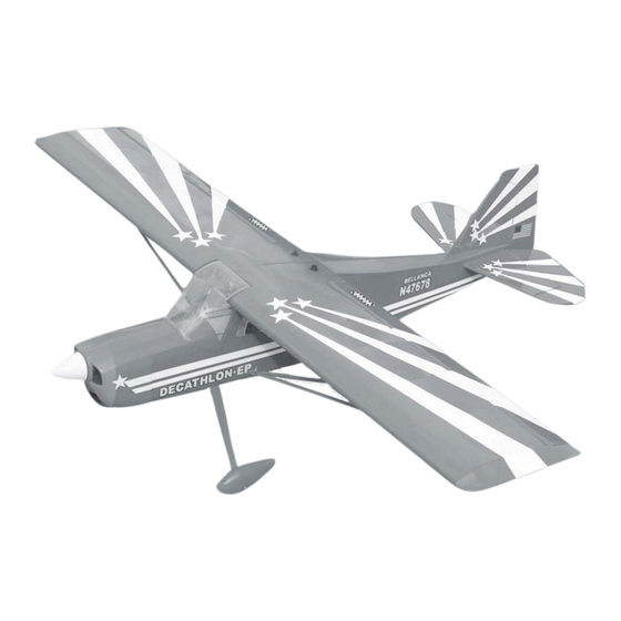
SPECIFICATION
Wingspan :
Length
Weight
Parts listing required (not included) .
Battery: 3 CELLS-LI-POLY-11.1V-2,500 mA.h.
Electric motor : + AXI 2808/24.
Radio
Servo
Speed control :
Instruction Manual book
1,250mm
:
930mm
:
1.1kg
+ KMS 2814/08
:
04 channels.
:
04 servos.
25A.
49.21 in.
36.61in.
2.42 Lbs.
Made in Vietnam.
Advertisement
Table of Contents

Subscribe to Our Youtube Channel
Related Manuals for Black Horse Model DECATHLON-EP


Summary of Contents for Black Horse Model DECATHLON-EP
- Page 1 Instruction Manual book SPECIFICATION Wingspan : 1,250mm 49.21 in. Length 930mm 36.61in. Weight 1.1kg 2.42 Lbs. Parts listing required (not included) . Battery: 3 CELLS-LI-POLY-11.1V-2,500 mA.h. Electric motor : + AXI 2808/24. + KMS 2814/08 Radio 04 channels. Servo 04 servos. Speed control : 25A.
- Page 2 DECATHLON - EP. INSTRUCTION MANUAL This instruction manual is designed to help you build a great flying aeroplane. Please read this manual thoroughly before starting assembly of your DECATHLON-EP. Use the parts listing below to identify all parts. WARNING. Please be aware that this aeroplane is not a toy and if assembled or used incorrectly it is capable of causing injury to people or property.
-
Page 3: Safety Precaution
DECATHLON-EP. INSTRUCTION MANUAL INSTALLING THE AILERON SERVOS. SAFETY PRECAUTION. + This is not a toy 1. Install the rubber grommets and brass + Be sure that no other flyers are using your eyelets onto the aileron servo. radio frequency. The glow plug clip must be securely attached to the glow plug. - Page 4 DECATHLON - EP. INSTRUCTION MANUAL C/A glue Bottom side 4. Using the thread as a guide and using masking tape, tape the servo lead to the end of the thread: carefully pull the thread out. When you have pulled the servo lead out, remove the masking tape and the servo lead from the thread.
- Page 5 DECATHLON-EP. INSTRUCTION MANUAL Remove the covering on to the pre-cut slot of Wing. aileron at picture. Servo tray. 6. Using a modeling knife, remove the Remove covering wing. covering R e m o v e covering C/A glue Repeat the procedure for the other wing half.
-
Page 6: Joining The Wing Halves
DECATHLON - EP. INSTRUCTION MANUAL Repeat the procedure for the other wing half. JOINING THE WING HALVES. 1. Locate the aluminium wing dihedral brace. 2. Test fit the dihedral brace into each wing half. The brace should slide in easily. C/A glue. - Page 7 DECATHLON-EP. INSTRUCTION MANUAL Secure 3 x 15mm Motor mount wood INSTALLING THE COWLING-SPINNER. Push 1. Slide the fiberglass cowl over the en- gine and line up the back edge of the cowl with the marks you made on the fuselage.
-
Page 8: Installing The Spinner
DECATHLON - EP. INSTRUCTION MANUAL 2. While keeping the back edge of the INSTALLING THE SPINNER. cowl flush with the marks, align the front of the cowl with the crankshaft of the engine. The front of the cowl should be positioned so the crankshaft is in nearly the middle of the cowl opening. - Page 9 DECATHLON-EP. INSTRUCTION MANUAL Mark point Drill a hole 3mm diameter. M3 lock Wooden collars Metal plate 3mm C/A glue Wooden collars Metal plate 3mm Wooden collars M3 lock M3 lock Metal plate 3mm 2) A drop of C/A glue on the wheel collar screws will help keep them from coming lose during operation.
-
Page 10: Installing The Main Landing Gear
DECATHLON - EP. INSTRUCTION MANUAL INSTALLING THE MAIN LANDING GEAR ELEVATOR INSTALLATION. SERVO INSTALLATION. 1) The blind nuts are already mounted in- 1. Install the rubber grommets and brass side the fuselage. collets into the elevator servo. Test fit the servo into the servo tray. -
Page 11: Horizontal Stabilizer Installa- Tion
DECATHLON-EP. INSTRUCTION MANUAL HORIZONTAL STABILIZER INSTALLA- Top side TION. 1) Draw a center line onto the horizontal stabilizer. Then slide the horizontal into the fuselage. Mark line Bottom side Center line 2) Using a modeling knife, carefully re- move the covering from over the vertical sta- bilizer mounting slot in the top of the fuselage. -
Page 12: Control Horn Installation
DECATHLON - EP. INSTRUCTION MANUAL Remove covering C/A glue 6) When you are sure that everything is aligned correctly, mix up a generous amount of Flash 30 Minute Epoxy. Apply a thin layer to the mounting slot in the top of the fuselage and to the sides and bottom of the vertical stabilizer mounting area. -
Page 13: Elevator Pushrod Installation
DECATHLON-EP. INSTRUCTION MANUAL Remove the covering in to the pre-cut slot of elevator as picture. Remove covering Elevator Elevator pushrod pushrod Secure Secure C/A glue ELEVATOR PUSHROD INSTALLATION. Elevator pushrod install as same as the way of aileron pushrod. -
Page 14: Vertical Installation
DECATHLON - EP. INSTRUCTION MANUAL C/A glue Elevator servo C/A glue VERTICAL INSTALLATION. MOUNTING THE TAIL WHEEL BRACKET. See pictures below: C/A glue Nilon clasp. Tail gear. 1) Using a modeling knife, remove the covering from the top of the fuselage and the covering from over the precut hinge slot cut into the lower rear portion of the fuselage This 1. - Page 15 DECATHLON-EP. INSTRUCTION MANUAL 4) Remove the stabilizer. Using a mod- eling knife, remove the covering from below the lines you drew. Also remove the covering from the bottom edge of the stabilizer and the bottom and top edges of the filler block. Leave the covering in place on the sides of the filler block.
-
Page 16: Rudder Pushrod Installation
DECATHLON - EP. INSTRUCTION MANUAL CONTROL HORN INSTALLATION. Epoxy glue Rudder control horn. Control horns rudder as same as method of aileron wing. See pictures below: C/A glue Remove covering 6) When you are sure that everything is aligned correctly, mix up a generous amount of Flash 30 Minute Epoxy. - Page 17 DECATHLON-EP. INSTRUCTION MANUAL Rudder servo Elevator servo INSTALLING THE RECEIVER AND BATTERY. See picture below. Elevator Elevator pushrod pushrod Rudder pushrod Secure Battery...
-
Page 18: Wing Joining
DECATHLON - EP. INSTRUCTION MANUAL Wing bolt Receiver WING JOINING. Wing attach to fuselage. WING STRUT INSTALLATION Mark point See picture: Wing bolt plate Wing strut 3 X 15mm... - Page 19 DECATHLON-EP. INSTRUCTION MANUAL Remove covering on the pre-cut slot of hole. Secure...
-
Page 20: Control Throws
4) Check the control surface. 5) Check the receiver antenna . It should be fully extended and not coiled up inside the 65mm fuselage. 6) Properly balance the propeller. We wish you many safe and enjoyable flights with your DECATHLON-EP.
Need help?
Do you have a question about the DECATHLON-EP and is the answer not in the manual?
Questions and answers