Black Box ServSwitch Manual
Hide thumbs
Also See for ServSwitch:
- User manual (115 pages) ,
- Manual (32 pages) ,
- Installing and operating information (2 pages)

Related Manuals for Black Box ServSwitch


Summary of Contents for Black Box ServSwitch
- Page 1 November 2009 ACX0000 ACX0832 ACX0808 ACX1616 ACX0816 ACX1632 ServSwitch Manual http://www.blackbox.com...
- Page 2 ServSwitch™- Extender technology for the transmission of DVI- Monitor and USB-Keyboard and Mouse signals over CATx cable. The operation of a ServSwitch™ DKM always requires up to 32 Local Units and up to 16 Remote Units from the ServSwitch™-Extenders range.
- Page 3 (keyboard/mouse) signals. Its flexibility allows it to tackle almost every task. There are 8 pre-configured ServSwitch™ DKMes for CATx as well as an empty chassis for individual configuration. In addition, there are 4 Media Extenders (DVI + optional audio) and 8 KVM- Extenders (DVI+USB keyboard mouse + optional audio) available.
- Page 4 ACS4222A-T: ServSwitch™- KVM Local Unit, +Audio, Dual-Head ACS4004A-T: ServSwitch™-KVM Local Unit, Single-Head, 4x USB-HID ACS4204A-T: ServSwitch™-KVM Local Unit, Dual-Head, 4x USB-HID ACS4002A-T: ServSwitch™- KVM Local Unit, +USB2.0, Single Head ACS4011A-T: ServSwitch™- KVM Local Unit, +VGA, Single-Head ACS4100A-R: ServSwitch™-Media Remote Unit ACS4122A-R: ServSwitch™-Media Remote Unit, +Audio...
- Page 5 ACS4222A-T-MM: ServSwitch™- KVM Local Unit, +Audio, Dual-Head ACS4004A-T-MM: ServSwitch™-KVM Local Unit, Single-Head, 4x USB-HID ACS4204A-T-MM: ServSwitch™-KVM Local Unit, Dual-Head, 4x USB-HID ACS4002A-T-MM: ServSwitch™- KVM Local Unit, +USB2.0, Single Head ACS4011A-T-MM: ServSwitch™- KVM Local Unit, +VGA, Single-Head ACS4100A-R-MM: ServSwitch™-Media Remote Unit ACS4122A-R-MM: ServSwitch™-Media Remote Unit, +Audio...
- Page 6 ACS4222A-T-SM: ServSwitch™- KVM Local Unit, +Audio, Dual-Head ACS4004A-T-SM: ServSwitch™-KVM Local Unit, Single-Head, 4x USB-HID ACS4204A-T-SM: ServSwitch™-KVM Local Unit, Dual-Head, 4x USB-HID ACS4002A-T-SM: ServSwitch™- KVM Local Unit, +USB2.0, Single Head ACS4011A-T-SM: ServSwitch™- KVM Local Unit, +VGA, Single-Head ACS4100A-R-SM: ServSwitch™-Media Remote Unit ACS4122A-R-SM: ServSwitch™-Media Remote Unit, +Audio...
-
Page 7: Copyrights And Trademarks
ServSwitch™ DKM Copyrights and Trademarks ©2009. All rights reserved. This information may not be reproduced in any manner without the prior written consent of the manufacturer. Information in this document is subject to change without notice and the manufacturer shall not be liable for any direct, indirect, special, incidental or consequential damages in connection with the use of this material. - Page 8 EMPTY PAGE...
-
Page 9: Ec Declaration Of Conformity
ServSwitch™ DKM EC DECLARATION OF CONFORMITY The products listed below in the form as delivered are in conformity with the provisions of the following European Directives: 2004/108/EG Council Directive on the approximation of the laws of the Member States relating to electromagnetic compatibility... -
Page 10: Power Input
SAFETY PRECAUTIONS AND INSTALLATION GUIDLINES Safety Precautions and Installation Guidelines To ensure reliable and safe long-term operation, please note the following installation guidelines: Do not use CATx- devices to link between buildings – please use fibre devices. Only use in dry, indoor environments. ... -
Page 11: Table Of Contents
ServSwitch™ DKM Contents 1 Quick Setup 2 Overview 2.1 Introduction 2.2 Glossary 17 2.3 Example of a ServSwitch™ DKM System 2.4 Features 19 2.5 Product Range 2.6 Compatibility 2.7 How to Use This Guide 2.7.1 Connection & Compatibility 2.7.2 DDC Information 2.7.3... - Page 12 Display of CPU-/CON-Ports Status 7.4.5 Display of Network Status 7.4.6 Display of Flash Status 7.4.7 Display of Tasks Status 8 Control of ServSwitch™ DKM 8.1 Instant Switching 8.1.1 Keyboard Hot Keys 8.1.2 Changing the default Instant Switching Hotkey 8.1.3 Macro Keyboard 8.1.4...
- Page 13 Appendix G: Specifications Appendix H: Connectors Appendix I: ServSwitch™ Media/KVM Extender I.1. ServSwitch™- Media Extender I.2. ServSwitch™- KVM Extender I.3. Diagnostics of ServSwitch™- Media/ KVM I.4. Service Setup Extenders I.5. Setup at the Local Unit I.6. Setup at the Remote Unit...
- Page 14 CONTENTS I.7. Devices with serial/audio option I.8. Specifications ServSwitch™-Media/KVM Units I.9. Connectors ServSwitch™-Media/KVM Units...
-
Page 15: Quick Setup
ServSwitch™ DKM 1 Quick Setup This section briefly describes how to install your ServSwitch™ DKM system. Unless you are an experienced user, we recommend that you follow the full procedures described in the rest of this manual. Installation of the system Connect ServSwitch™... -
Page 16: Overview
OVERVIEW 2 Overview 2.1 Introduction The ServSwitch™ DKM can be set up to support four different applications: Crosspoint Switch: Maximum configuration (without cascading) of 32 input ports and 16 output ports. Optionally, in reverse mode, the device supports a maximum of 16 input ports and 32 output ports. - Page 17 A ServSwitch™ DKM system comprises a ServSwitch™ DKM and one or more Local/Remote Units. The ServSwitch™ DKM and the Local/ Remote Units are attached by CATx or Fibre interconnection cables. The operation of a ServSwitch™ DKM requires always the use of Local Units and Remote Units of a ServSwitch™-Extender.
-
Page 18: Glossary
(www.ddwg.org) R, G, B, CLOCK in a data stream with up to 3x1,6 Gbit/sec. Signals are TMDS Level. The desktop power supply connected to the ServSwitch™ DKM or to the Local/ Remote Unit. Human Interface Devices are units, which are used for human access to the CPU: keyboard and mouse, touch-screen, light pen, fingerprint sensor, graphic tablets etc. -
Page 19: Example Of A Servswitch™ Dkm System
ServSwitch™ DKM 2.3 Example of a ServSwitch™ DKM System Application example for a ServSwitch™ DKM System (Single-Head KVM Switch) -
Page 20: Features
USB hub but this does not raise the number of supported devices. Maximum length of interconnection cable from a Local Unit to a ServSwitch™- Minor Switch, between two ServSwitch™- Minor Switches or from a ServSwitch™- Minor Switch to a Remote Unit). - Page 21 ServSwitch™ DKM Dual-Head Devices support TxD and RxD ONLY – no Hardware handshake (XON/XOFF)
-
Page 22: Product Range
2.5 Product Range The following products are available as well as various upgrade kits: ServSwitch™ DKM and Accessories ACX0808 ServSwitch™ DKM for 8 Users and 8 CPUs (CATx) ACX0816 ServSwitch™ DKM for 8 Users and 16 CPUs (CATx) ACX0824 ServSwitch™ DKM for 8 Users and 24 CPUs (CATx) ACX0832 ServSwitch™... - Page 23 ServSwitch™ DKM Media Extenders ACS4100A-T ServSwitch™-Media Local Unit (CATx) ACS4122A-T ServSwitch™-Media Local Unit + Audio (CATx) ACS4100A-R ServSwitch™-Media Remote Unit (CATx) ACS4122A-R ServSwitch™-Media Remote Unit + Audio (CATx) ACS4100A-T-MM ServSwitch™-Media Local Unit (Multimode) ACS4122A-T-MM ServSwitch™-Media Local Unit + Audio (Multimode) ACS4100A-R-MM ServSwitch™-Media Remote Unit (Multimode)
- Page 24 KVM Extenders for Multimode ACS4001A-T-MM ServSwitch™-KVM Local Unit, Single-Head ACS4201A-T-MM ServSwitch™-KVM Local Unit, Dual-Head ACS4022A-T-MM ServSwitch™-KVM Local Unit, + Audio, Single-Head ACS4222A-T-MM ServSwitch™-KVM Local Unit, + Audio, Dual-Head ACS4004A-T-MM ServSwitch™-KVM Local Unit, Single-Head, 4x USB-HID ACS4204A-T-MM ServSwitch™-KVM Local Unit, Dual-Head, 4x USB-HID ACS4002A-T-MM ServSwitch™-KVM Local Unit, Single-Head, 4x USB-2.0...
- Page 25 AC1038A DVI-D to VGA Converter, to connect the local output to a traditional VGA-KVM-Switch ACXCWDM4 CWDM MUX/DEMUX to send up to 4 ServSwitch™ fiber interconnections simultaneously over only two fibres ACX1000 CATx Repeater to double the maximum allowed distance to up to 280m (also available for Multi-/Singlemode)
-
Page 26: Compatibility
(Human Interface Device) such as touch screens, graphics tablets, barcode readers or similar may be successful – but there is no guarantee for this! The ServSwitch™- KVM standard device is NOT suitable for use with other USB- devices such as scanners, web- cams, data sticks etc. -
Page 27: How To Use This Guide
For information about connection and installation, see page 30. 2.7.2 DDC Information Normally, it is not necessary to make any adjustments to the ServSwitch™- KVM/ Media device. However, in some circumstances, it may be necessary to redefine the source of DDC information for the CPU. -
Page 28: Selection Of Color Reduction For Transfer Acceleration
OVERVIEW 2.7.4 Selection of Color reduction for transfer acceleration You can select, whether always 24 Bit colors (=full color depth) are transmitted or whether the compression algorithm automatically switches between 16 and 24 Bit colors to accelerate the data transfer (default). Normally the difference between 24 Bit and 16 Bit is not recognizable but under some special circumstances e.g. -
Page 29: Installation
This will allow you to identify and solve any cabling problems and experiment with the ServSwitch™ DKM System more conveniently. 3.1 Package Contents You should receive the following items in your ServSwitch™ DKM for CATx package: ServSwitch™ DKM ... - Page 30 The following parts should be in your ServSwitch™- KVM/ Media Remote Unit package: ServSwitch™- KVM/ Media Remote Unit 1x 5V DC universal power supply for the ServSwitch™- KVM/ Media Remote Unit 1x German type power cord User manual (Quick Setup)
-
Page 31: Teacher/Student System
ServSwitch™ DKM 3.2 Interconnection Cable Requirements To connect the ServSwitch™-Media Local Unit to your CPU/signal source you will need (Please ensure that the connection is tension-free!): DVI: Connect the supplied DVI-cable 1.8m (DVI-I male to DVI-I male) to your CPU (KVM- Switch, DVI- signal source, etc.). - Page 32 Multimode cable! This cannot be guaranteed, however, and must be verified by the user at own risk and cost. Power Supply: Connect the supplied 5V/DC power supply to the ‘POWER’ socket of the ServSwitch™ Local Unit or ServSwitch™ Remote Unit.
-
Page 33: System Setup
Connect keyboard, monitor(s), mouse to the Remote Unit (depending on device type). Connect the CPU/signal source to the Local Unit using the supplied cable(s). Connect the ServSwitch™ Local units and Remote units with the INTERCONNECT cable(s) (CATx or Fibre) Connect the ServSwitch™ DKM with the INTERCONNECT cable(s) (CATx / Fibre) Type 474-8X only: Equip the Cage sockets with GBICs according to your desired configuration. -
Page 34: Installation Instructions
INSTALLATION 3.4 Installation Instructions Please ensure that the ServSwitch DKM has sufficient ventilation space by ensuring the following distances between the unit and other devices and/or mounting parts: Space directions while putting the device onto a desk Space directions while mounting the device into a 19” rack The ServSwitch™... -
Page 35: Device Views
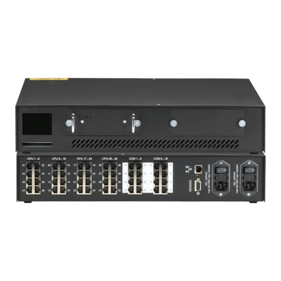
ServSwitch™ DKM 4 Device Views 4.1 ServSwitch™ DKM Plug-in Power Supply Bay for optional second Status and 100-240VAC 50-60Hz Plug-in Power Supply Configuration Display Slot for IR Remote Control... - Page 36 DEVICE VIEWS Network, Serial, USB Connect to AC Power Connect to Local Interfaces Supply Units (CPU) Connect to Remote Units (Console) Rear View with two AC Sockets for redundant Power Supply...
-
Page 37: Diagnostic
ServSwitch™ DKM 5 Diagnostic 5.1 ServSwitch™ DKM – I/O Boards Each ServSwitch™ DKM I/O Board is fitted with indicator LEDs for status diagnostics. The location of the LEDs is shown below: Diagnostic LED Diagnostic LED Link Status Link Status Right Socket... - Page 38 DIAGNOSTIC Diagnostic LEDs at Fibre I/O Boards The Link Status LED are located between the upper and the lower fibre sockets. LED indicates the status of the left connection, the LED indicates the status of the right connection. Appearance Diagnostics Green blinking Port activated, signal OK.
-
Page 39: Servswitch™ Dkm Configuration
ServSwitch™ DKM 6 ServSwitch™ DKM Configuration The ServSwitch™ DKM has an own operating system that can be configured in five different ways: By means of a console connected to a console port and the On-Screen Display (OSD) By means of a PC, a Browser and the web interface (under development) ... - Page 40 SERVSWITCH™ DKM CONFIGURATION 6.1.1.3 General frame structure of the OSD: Upper status area Work area Lower status area 6.1.1.4 Upper Status Area (left corner) Name of the current Operating mode of the Name of the user console port current console port...
- Page 41 ServSwitch™ DKM (right corner) Function Key Description 6.1.1.5 Lower Status Area (left corner) Name of the current device (right corner) Product description 6.1.1.6 Working Area The possible inputs are described with the respective OSD frame description.
-
Page 42: Keyboard Control
SERVSWITCH™ DKM CONFIGURATION Example: Menu Example: Input Mask Mask fields: Name Text field with xx characters Type Selection field Numerical field with xx digits 6.1.1.7 Keyboard Control: Within the masks you may navigate with the following keys (key sequences) <Cursor left>... - Page 43 ServSwitch™ DKM <-> Previous Option in Select fields <SPACE> Switch in selection fields with two options only (On/Off or No/Yes) Only if „Allow Sharing“ active: Apply and save data in Mask „KVM- Switch“ <RETURN> Apply and save data – in Input Masks Select option –...
-
Page 44: Open „Configuration" Menu
SERVSWITCH™ DKM CONFIGURATION 6.1.2 Open „Configuration“ Menu Please perform the following steps: Enter into the OSD with key sequence <Strg>+ <Shift>+ <O> (Letter ‚o’) The “KVM List” Mask is displayed full screen (If Option “Listview” is not active, “KVM Switch” Mask will be displayed instead). - Page 45 ServSwitch™ DKM All configuration adjustments require administrator rights. At delivery the following default user account is pre-defined: User admin (case sensitive) Password admin (case sensitive) Please modify this password at the first login. After successful login the “Configuration” menu is displayed: Default selection is “System”.
-
Page 46: Load Configurations
SERVSWITCH™ DKM CONFIGURATION 6.1.3 Load Configurations Please select the option “Open” in the “Configuration” menu by using the cursor buttons and confirm with <RETURN> The “Open” mask is displayed full screen. In this menu, you can load any switch configuration that has been previously stored within the switch. -
Page 47: System Configurations
ServSwitch™ DKM 6.1.4 System Configurations Please select the option “System” in the “Configuration” menu by using the cursor buttons and confirm with <RETURN>. The “System” mask is displayed full screen. In this menu, you can set and modify the switch configuration. - Page 48 SERVSWITCH™ DKM CONFIGURATION System Options: Field Selection Description (Input) Configuration name. Name CHR16 Used for saving the current configuration to file. (Input) Device name Device CHR16 (displayed in all menus at the lower left) (Input) Detailed information about the current...
- Page 49 ServSwitch™ DKM Access Options: Field Selection Description Y – Login required to access the OSD with user name and password. After login, the user will remain logged in until he explicitly logs out or an Auto Logout has Enable Login been performed (cf.
- Page 50 SERVSWITCH™ DKM CONFIGURATION Switch Options: Field Selection Description Y – User may connect to any unlocked CPU with Video Access only. Note: Switch with <Space> Key, Allow Sharing no <Return>. N – No Sharing. Y – User may connect to any unlocked CPUwith full...
- Page 51 ServSwitch™ DKM Mouse Options Field Selection Description Setting up the horizontal mouse speed Hor. Speed VAL2 Setting up the vertical mouse speed. Ver. Speed VAL2 Setting up the time frame for ‚double click’ Mouse Click VAL3 Mouse settings are CON Port specific and can be adjusted for each CON...
-
Page 52: Touch Screen Settings
SERVSWITCH™ DKM CONFIGURATION 6.1.5 Touch Screen Settings The ServSwitch™ DKM OSD supports touch screens. USB HID based Touch Screen protocols are supported. Support of Vendor specific protocols only upon request. From „System“mask, you can enter into „Touchscreen” Mask by hitting <F1>. -
Page 53: Configuration Of User Attributes
ServSwitch™ DKM 6.1.6 Configuration of User Attributes Please select the option “User” in the “Configuration” menu by using the cursor buttons and confirm with <RETURN>. The “User” mask is displayed full screen. In this menu, you can setup users with their names and privileges. -
Page 54: User Matrix Configuration
SERVSWITCH™ DKM CONFIGURATION 6.1.7 User Matrix Configuration Please select the option “User Matrix” in the “Configuration” menu by using the cursor buttons and confirm with <RETURN>. The “User Matrix” mask is displayed full screen. In this menu, the administrator can define for each user a specific set of CPU’s that this user might connect to. - Page 55 ServSwitch™ DKM Select all CPU’s None Clear all CPU’s SAVE Apply and save data CANCEL Cancel data input without saving The options „All“ and „None“ need to be confirmed by „Save“ or may be cancelled by „Cancel“!
-
Page 56: Configuration Of Con Ports
„System“ menu or the switch has been restarted. It further might require to re-power the ServSwitch™ DKM. For the OSD selection please note: Selection „VAR“(default) displays the OSD with 800x600 size at the center of the monitor without changing the current monitor resolution. - Page 57 ServSwitch™ DKM Configuration Options: Field Type Description Name CHR16 Name of the CON Port connected to this CPU Port SH = Single-Head Port DH = Dual-Head Port QH = Quad-Head Port Type SELECT 0U = USB2.0 Port 1U = Single-Head Port with USB2.0 Port 3U = Triple-Head Port with USB 2.0 Port...
-
Page 58: Con Matrix Configuration
SERVSWITCH™ DKM CONFIGURATION 6.1.9 CON Matrix Configuration Please select the option “CON Matrix” in the “Configuration” menu by using the cursor buttons and confirm with <RETURN>. The “CON Matrix” mask is displayed full screen. In this menu, the administrator can define for each console a specific set of CPU’s that this console might connect to. - Page 59 ServSwitch™ DKM Select all CPU’s None Clear all CPU’s SAVE Apply and save data CANCEL Cancel data input without saving The options „All“ and „None“ need to be confirmed by „Save“ or may be cancelled by „Cancel“!
-
Page 60: Configuration Of Cpu Ports
SERVSWITCH™ DKM CONFIGURATION 6.1.10 Configuration of CPU Ports Please select the option “CPU Ports” in the “Configuration” menu by using the cursor buttons and confirm with <RETURN>. The “CPU Ports” mask is displayed full screen. In this menu, the administrator can define for each CPU Port the name, the type, and the connected CON Port. -
Page 61: Configuration Of Network Parameters
Please select the option “Network” in the “Configuration” menu by using the cursor buttons and confirm with <RETURN> The “Network” mask is displayed full screen. In this menu, the administrator can define the parameters for the ServSwitch™ DKM IP network interface. The functionality of the network interface is described in Appendix D: Network Interface (p. -
Page 62: Programming Of Macros
SERVSWITCH™ DKM CONFIGURATION 6.1.12 Programming of Macros Please select the option “Macro Keys” in the “Configuration” menu by using the cursor buttons and confirm with <RETURN>. The “Macro Keys” mask is displayed full screen. This section describes the programming of switch macros. The macros will be stored for each console separately. - Page 63 ServSwitch™ DKM Configuration Options: Field Type Description Number of the command (8 commands max) Select Connect P1 to P2 Command Select Bidirectional Connection of CON Port P1 with CPU P2 Connect Video P1 to P2 Video Connection of CON Port P1 with CPU P2...
-
Page 64: Saving Configurations Inside The Switch
SERVSWITCH™ DKM CONFIGURATION 6.1.13 Saving Configurations inside the Switch Please select the option “Save” in the “Configuration” menu by using the cursor buttons and confirm with <RETURN>. By selecting this option the current configuration will be saved into the internal switch memory. -
Page 65: Saving Configurations Into File
ServSwitch™ DKM 6.1.14 Saving Configurations into File Please select the option “Save as” in the “Configuration” menu by using the cursor buttons and confirm with <RETURN>. The “Save as” mask is displayed full screen. In this menu, you can save your current switch configuration to file. This does not replace saving the configuration within the switch. -
Page 66: Restart Your Switch
SERVSWITCH™ DKM CONFIGURATION 6.1.15 Restart your Switch In the “Configuration” menu you can select from three options to restart the ServSwitch™ DKM: 6.1.15.1 Restart By selecting „Restart“ the ServSwitch™ DKM will reboot with its current configuration. Exception: If the parameter „Load Default“ in menu „System“ has been selected, the switch will boot with the default configuration. -
Page 67: Configuration Via Browser And Web Interface
ServSwitch™ DKM 6.2 Configuration via Browser and Web Interface The Web Interface is under development. In Browser mode, similar masks will be generated and displayed. Accordingly, configuration is similar, independent from the method of access. Please refer to the commands of the OSD, starting at Configuration via Console at page 38. -
Page 68: Configuration Via Serial Interface
SERVSWITCH™ DKM CONFIGURATION 6.3 Configuration via Serial Interface The ServSwitch™ DKM can currently be switched but not be configured via Serial Interface. All available telegrams are listed in Appendix C: Serial Interface (page 133). -
Page 69: Configuration Via Ir Remote Control And Lcd-Display
6.4 Configuration via IR Remote Control and LCD- Display The ServSwitch™ DKM can be configured via the IR Remote Control and the LCD Display in the following, limited way. For full functionality, please refer to the OSD Interface or the Web Interface. -
Page 70: Home Mask
SERVSWITCH™ DKM CONFIGURATION 6.4.2 Home Mask During regular operation, the Home Mask is displayed. In this Display you’ll find some device information: ServSwitch DKM 05.05.09 B02.04 Black Box Corporation 1000 Park Drive Lawrence/PA United States +1 724 746 55000 ServSwitch DKM 6.4.3... -
Page 71: Configuration Mask
ServSwitch™ DKM 6.4.4 Configuration Mask Please select the option “Configuration” in the “Menu Mask” by using the cursor buttons and confirm with <RETURN>. Configuration Network System Restart Reset ServSwitch DKM... -
Page 72: Configuration Of Network Parameters
<RETURN>. The “Configuration Network” mask is displayed full screen. In this menu, you can define the parameters for the ServSwitch™ DKM IP network interface. The functionality of the network interface is described in Appendix D: Network Interface (p. -
Page 73: Configuration Of System Parameters
Please select the option “System” in the “Configuration Mask” by using the cursor buttons and confirm with <RETURN>. The “Configuration System” mask is displayed full screen. In this menu, you can define some parameters for the ServSwitch™ DKM system configuration. Configuration... - Page 74 SERVSWITCH™ DKM CONFIGURATION Access Options: Field Type Description Y – Login required to access the OSD with user name and password. After login, the user will remain logged in until he explicitly logs out or an Auto Logout has Login been performed (cf.
-
Page 75: Restart Your Switch
Please select the option “Reset” in the “Configuration Mask” by using the cursor buttons and confirm with <RETURN>. 6.4.8.1 Reset By selecting „ Reset“ the ServSwitch™ DKM will reboot with the original factory configuration. Exception: After a firmware update the ServSwitch™ DKM will reboot with the firmware configuration... -
Page 76: Configuration Via Ftp
6.5.1 FTP Access to Configuration Files For ftp access to the configuration file directory the ServSwitch™ DKM must be connected to a network and the network interface has to be properly configured (cf. Xxx). In this case you can access the configuration file directory from any browser with the following command: ftp://user:password@xxx.xxx.xxx.xxx... -
Page 77: External Saving Of Configuration Files
ServSwitch™ DKM 6.5.2 External Saving of Configuration Files Open the configuration directory as described above. Save the selected Configuration File to an external storage media. This configuration file will work with the current switch firmware. Compatibility with future firmware updates is possible, but cannot be guaranteed. -
Page 78: Status Information
STATUS INFORMATION 7 Status Information The status information of the ServSwitch™ DKM can be displayed in four different ways: By means of a console connected to a console port via OSD By means of a PC, a Browser and the web interface (under development) ... -
Page 79: Status Display Via Console And Osd
ServSwitch™ DKM 7.1 Status Display via Console and OSD 7.1.1 Open the „Status“ Menu Please perform the following steps: Enter into the OSD with key sequence <Strg>+ <Shift>+ <O> (Letter ‚o’) The “KVM List” Mask is displayed full screen (If Option “Listview” is not active, “KVM Switch” Mask will be displayed instead). -
Page 80: Status Display Of Con Ports
STATUS INFORMATION 7.1.2 Status Display of CON Ports Please select the option “CON Ports” in the “Status” menu by using the cursor buttons and confirm with <RETURN>. The “Status CON Ports” mask is displayed full screen. In this status view it is shown, which console has connections to which CPU. Pressing the ‘F1’... - Page 81 ServSwitch™ DKM Displays Number of CPU port with Number of CPU port(s) with KVM connection monitor connection only (monitor + keyboard/mouse) Number of current Name of current CON Port CON Port...
-
Page 82: Status Display Of Cpu Ports
STATUS INFORMATION 7.1.3 Status Display of CPU Ports Please select the option “CPU Ports” in the “Status” menu by using the cursor buttons and confirm with <RETURN>. The “Status – CPU Ports” mask is displayed full screen. In this status view it is shown, which CPU has connections to which console. Easily to detect in this view is, if the display of one CPU is displayed on several monitors. - Page 83 ServSwitch™ DKM Displays Number of User port with Number of User port(s) with KVM connection monitor connection only (monitor + keyboard/mouse) Number of current Name of current CPU Port CPU Port...
-
Page 84: Display Of Network Status
STATUS INFORMATION 7.1.4 Display of Network Status Please select the option “Network” in the “Status” menu by using the cursor buttons and confirm with <RETURN>. The “Network” mask is displayed full screen. This status view shows the complete network configuration. Display: Interface: Field Description... - Page 85 ServSwitch™ DKM Display: Statistics – Number of Packets received/transmitted: Field Description Number of Packets with errors Errors Number of Packets dropped Dropped Station Broadcast Number of Bytes received/transmitted Bytes...
-
Page 86: Display Of Firmware Status
STATUS INFORMATION 7.1.5 Display of Firmware Status Please select the option “Firmware” in the “Status” menu by using the cursor buttons and confirm with <RETURN>. The “Status Firmware” mask is displayed full screen. This status view shows on two pages the firmware versions of the currently installed boards inside the switch. - Page 87 ServSwitch™ DKM Page II of “Status Firmware”...
-
Page 88: Status Display Via Browser / Web Interface
STATUS INFORMATION 7.2 Status Display via Browser / Web Interface The Web Interface is under development. In Browser mode, status display of the ServSwitch™ DKM will be performed similarly to the OSD mode. Similar masks are generated and displayed. -
Page 89: Status Display Via Serial- Interface
ServSwitch™ DKM 7.3 Status Display via Serial- Interface The ServSwitch™ DKM provides limited status information via Serial Interface. Available Telegrams provide information about the current switch matrix. All available telegrams are listed in Appendix C: Serial Interface (p. 133). -
Page 90: Status Display Via Lcd-Display
STATUS INFORMATION 7.4 Status Display via LCD-Display The ServSwitch™ DKM provides various functions to display status information via LCD- Display. 7.4.1 Home Mask During regular operation, the Home Mask is displayed. In this Display you’ll find some device and manufacturer information: ServSwitch DKM 05.05.09... -
Page 91: Status Mask
ServSwitch™ DKM 7.4.3 Status Mask From the „Menu“ Mask you open the „Status“ Mask by pressing <RETURN>. Status Ports Network Flash Tasks ServSwitch DKM 7.4.4 Display of CPU-/CON-Ports Status Please select the option “Ports” in the “Status Mask” by using the cursor buttons and confirm with <RETURN>. -
Page 92: Display Of Network Status
CPU_06 n.c. CPU_07 n.c. CPU_08 n.c. ServSwitch DKM 7.4.5 Display of Network Status Please select the option “Network” in the “Status Mask” by using the cursor buttons and confirm with <RETURN>. The “Status Network” mask is displayed full screen. - Page 93 ServSwitch™ DKM Display: Interface: Field Description Display of dynamic network configuration status DHCP (‚YES’ or ‚NO’) Display of IP Address IP Address (as entered manually or received by DHCP) Display of Subnet Mask Subnet Mask (as entered manually or received by DHCP)
-
Page 94: Display Of Flash Status
Please select the option “Flash” in the “Status Mask” by using the cursor buttons and confirm with <RETURN>. The “Status Flash” mask is displayed full screen. Status Flash File ServSwitch DKM Navigation Options: <Line up> <Line down> <RETURN> Select option <ESC>... - Page 95 ServSwitch™ DKM Page 2 of „Status Flash Mask“ Status Flash File Filename Size config07.sys 3444 config08.sys 3444 modul.sys ServSwitch DKM Navigation Options: <Page up> Previous page <Page down> Next page <ESC> Return to „ Status Flash“ Mask System files that may not be modified are marked with an asterisk. All other files may be loaded, stored or deleted via ftp (see pages 45 and 64).
-
Page 96: Display Of Tasks Status
Flash CGI Script Procedure cgiTest1 0x00000D64 cgiTest2 0x00000D94 ServSwitch DKM Navigation Options: <ESC> Return to „ Status Flash“ Mask 7.4.7 Display of Tasks Status Please select the option “Tasks” in the “Menu Mask” by using the cursor buttons and confirm with <RETURN>... -
Page 97: Control Of Servswitch™ Dkm
ServSwitch™ DKM 8 Control of ServSwitch™ DKM The ServSwitch™ DKM can be operated in three different ways: a) Instant Switching: By means of a standard keyboard connected to a console port and hot keys By means of a macro keyboard connected to a console port b) Via Input Masks: ... -
Page 98: Instant Switching
CONTROL OF SERVSWITCH™ DKM 8.1 Instant Switching 8.1.1 Keyboard Hot Keys Instant Switching with Keyboard Hot Keys is the fastest way for a user to switch between various CPU’s. By hitting <Strg>+ <Shift>+ <I> (Letter ‚i’) the Hotkey Mode is activated: Shift-Lock- and Scroll-LED are flashing. -
Page 99: Macro Keyboard
8.1.4 Macros via Function keys of a standard keyboard Switching of the ServSwitch™ DKM can also be performed very efficiently via a standard Keyboard and its Function keys <F1>, <F2>…<F12>. Other than with the X-keys Macro Keyboard the standard keyboard will only offers twelve different macros to be used. -
Page 100: Switching In Osd / Kvm Mode
CONTROL OF SERVSWITCH™ DKM 8.2 Switching in OSD / KVM Mode In KVM Mode, the user can only switch his own console. To control other consoles, please refer to the Crosspoint switch section (see page 104). 8.2.1 Switching in „KVM-List“ Mask: This mask will appear as default as you enter into the OSD. - Page 101 ServSwitch™ DKM Color Codes CPU Port CON Port Meaning Green n.c. CPU Port not connected Video maybe shared to other console Green Yellow CPU Port not connected Video shared to own console Yellow Yellow CPU Port connected to own console...
-
Page 102: Switching In „Kvm-Switch" Mask
CONTROL OF SERVSWITCH™ DKM 8.2.2 Switching in „KVM-Switch“ Mask: This mask will appear as you enter into the OSD if the configuration has been modified accordingly. In this mask, all CPU Ports are displayed regardless of their accessibility. Color Codes... - Page 103 ServSwitch™ DKM Keyboard Commands <Cursor left> Cursor left <Cursor right> Cursor right <Cursor up> Line up <Cursor down> Line down <Tab> Next field <Shift> + <Tab> Previous field <SPACE> Select CPU Port Video only (Only if „Allow Sharing“ active or CPU available) <RETURN>...
-
Page 104: Switching In „Follow Me" Mask
CONTROL OF SERVSWITCH™ DKM 8.2.3 Switching in „Follow Me“ Mask: With the ‚ Follow Me’ option you can copy the display content from the CPU connected to your console to several other consoles (video only). Thus, the own display content can easily be displayed on one or more additional monitors. -
Page 105: Switching In Osd / Crosspoint Mode
ServSwitch™ DKM Color Codes CON Port CPU Port Meaning Green n.c. Available CON Port CON Port # connected to CPU Port # or to CON Port # in “Follow Me” Mode Black Black Own CON Port connection Black n.c. CON Port not available Keyboard Commands <Cursor left>... -
Page 106: Open The „Cp-Switch" Menu
CONTROL OF SERVSWITCH™ DKM 8.3.1 Open the „CP-Switch“ Menu Please perform the following steps: Enter into the OSD with key sequence <Strg>+ <Shift>+ <O> (Letter ‚o’) The “KVM List” Mask is displayed full screen (If Option “Listview” is not active, “KVM Switch” Mask will be displayed instead). -
Page 107: Switching In „Crosspoint Switch / Con Ports" Mask
ServSwitch™ DKM 8.3.2 Switching in „Crosspoint Switch / CON Ports“ Mask The upper two lines show to which The lower two lines show from which CPU keyboard/mouse are attached CPU the display content is displayed The lines correspond to the... - Page 108 CONTROL OF SERVSWITCH™ DKM Keyboard Commands: <Cursor left> Cursor left Select CPU Port to the left <Cursor right> Cursor right Select CPU Port to the right <Cursor up> Line above Select keyboard/mouse for current User Port or Select monitor for User Port one line above <Cursor down>...
-
Page 109: Switching In „Crosspoint Switch / Cpu Ports" Mask
ServSwitch™ DKM 8.3.3 Switching in „Crosspoint Switch / CPU Ports“ Mask“ To enter into the „Crosspoint Switch / CPU Ports“ mask from the Crosspoint Switch / CON Ports“ Mask press <F1>. Expert mode for free switching! Responsibility for switch result lies with the user! - Page 110 CONTROL OF SERVSWITCH™ DKM Keyboard Commands: <Cursor left> Cursor left Select User Port to the left <Cursor right> Cursor right Select User Port to the right <Cursor up> Line above Select monitor for current CPU Port or Select keyboard/mouse for CPU Port one line above <Cursor down>...
-
Page 111: Switching Via Browser / Web Interface
8.4 Switching via Browser / Web Interface The Web Interface is under development. In Browser mode, switching of the ServSwitch™ DKM will be performed similarly to the Switching in OSD / Crosspoint Mode (p. 104). Similar masks are generated and displayed. -
Page 112: Switching Via Serial Interface
CONTROL OF SERVSWITCH™ DKM 8.5 Switching via Serial Interface The ServSwitch™ DKM provides full Crosspoint switching functionality via Serial Interface. Telegrams allow switching of video only, K/M only and bidirectional switching. Additional telegrams allow loading, saving and defining the complete switch matrix in one step. -
Page 113: Switching Via Lcd-Display
ServSwitch™ DKM 8.6 Switching via LCD-Display The ServSwitch™ DKM cannot be switched via IR Interface and the LCD Display. There are only options available to restart the switch (see page 74). -
Page 114: Operating Modes
9 Operating Modes The ServSwitch™ DKM provides full flexibility for configuration of your Switch environment. One part of the ServSwitch™ DKM can be configured as Single-Head Ports, another part as Dual-Head- or even Quad-Head Ports. Additionally, there are mixed configurations of KVM and USB2.0 ports available. -
Page 115: Single-Head Kvm-Switch
ServSwitch™ DKM 9.1 Single-Head KVM-Switch In Single-Head Mode up to 16 Users can access up to 32 CPUs. NON-Blocking Access for all users is granted, i.e. none of the users is constrained by the activity of another user. Switch example: Single-Head KVM-Switch Via the OSD, each user can select the CPU that he wants to connect to. -
Page 116: Dual-Head Kvm-Switch
OPERATING MODES 9.2 Dual-Head KVM-Switch In Dual-Head Mode up to 8 Users can access up to 16 CPUs. NON-Blocking Access for all users is granted, i.e. none of the users is constrained by the activity of another user. Switch example: Dual-Head KVM-Switch with CPU-Splitter Via the OSD, each user can select the CPU that he wants to connect to. -
Page 117: Quad-Head Kvm-Switch
ServSwitch™ DKM 9.3 Quad-Head KVM-Switch In Quad-Head Mode up to 4 Users can access up to 8 CPUs. NON-Blocking Access for all users is granted, i.e. none of the users is constrained by the activity of another user. Switch example: Quad-Head KVM-Switch Via the OSD, each user can select the CPU that he wants to connect to. -
Page 118: Single-Head Kvm/Usb2.0 Mode
OPERATING MODES 9.4 Single-Head KVM/USB2.0 Mode In Single-Head KVM/USB2.0 Mode up to 8 Users with one USB2.0 link (for periphery devices e.g. storage devices, printers etc. in addition to keyboard & mouse) can access up to 16 CPUs. Up to 4 periphery devices can be attached directly to the remote unit, more by using regular USB 2.0 hubs. -
Page 119: Triple-Head Kvm/Usb2.0 Mode
ServSwitch™ DKM 9.5 Triple-Head KVM/USB2.0 Mode In Triple-Head KVM/USB2.0 Mode up to 4 Users each with one USB2.0 link (for periphery devices e.g. storage devices, printers etc. in addition to keyboard & mouse) can access up to 8 CPUs. Up to 4 periphery devices can be attached directly to the remote unit, more by using regular USB 2.0 hubs. -
Page 120: Teacher/Student System
OPERATING MODES 9.6 Teacher/Student System 15 The most flexible configuration can be granted if the system is used for up to 15 students. Each student place and the teacher’s place are connected by CATx Duplex cable. The following functions are available: ... -
Page 121: Teacher/Student System 30
ServSwitch™ DKM 9.7 Teacher/Student System 30 A larger, convenient configuration can be granted if the system is used for up to 30 students, with minor access restrictions. Each student place and the teacher’s place are connected by CATx Simplex cable. -
Page 122: Crosspoint Switch
OPERATING MODES 9.8 Crosspoint Switch The operation as a Crosspoint Switch allows the most flexible application of the switch functions. Usually, this operating mode will be used to connect up to 32 video source (and, optionally, audio sources) to up to 16 displays. In “Reverse Mode”, up to 16 video source (and, optionally, audio sources) can be connected to up to 32 displays. -
Page 123: Troubleshooting
ServSwitch™ DKM 10 Troubleshooting 10.1 Monitor There is no picture. Check the power supply connection at the Local and Remote Unit. Is the Power LED at the Local and Remote Unit illuminated? If not, the internal power supply may be damaged or there may be an internal error. -
Page 124: Usb Hid
TROUBLESHOOTING 10.2 USB HID 10.2.1.1 USB Keyboard/Mouse Your USB-keyboard/USB-mouse does not work Although we tried to design the devices as transparent as possible, we can’t ensure that all devices are running. Please check Appendix F: List of supported USB devices, on page 140. Your USB Mouse makes ”jerky leaps”... - Page 125 If you have any compatibility problems, please contact our technical support. 10.2.1.3 Other USB Devices Your USB- device does not work You have connected a non-HID device. The extender system supports HID devices only. All other devices are incompatible with the ServSwitch™ DKM system.
-
Page 126: Appendix A: Example Applications
APPENDIX A: EXAMPLE APPLICATIONS Appendix A: Example Applications This section illustrates some specific applications using the ServSwitch™ DKM: ServSwitch™ DKM as Dual-Head KVM Switch with additional Display... - Page 127 ServSwitch™ DKM ServSwitch™ DKM in „Control Room“ Mode for 3 Monitors each – 1x with optional monitor for operation...
- Page 128 APPENDIX A: EXAMPLE APPLICATIONS ServSwitch™ DKM as a Teacher/Student system for up to 30 Students...
- Page 129 ServSwitch™ DKM ServSwitch™- DKM as a Crosspoint Switch with optional serial/Audio Support...
-
Page 130: Appendix B: Rack Mount Options
APPENDIX B: RACK MOUNT OPTIONS Appendix B: Rack Mount Options The ServSwitch™ DKM can be mounted into a 19“/2U rack space using mounting plates (included). ServSwitch™ DKM Extenders can be mounted into 19“ Racks using Rackmount Kits. Two types of Rackmount Kits are available – for Single-Head and for Dual-Head Devices. - Page 131 ServSwitch™ DKM The rack mount kit ACS1009A-RMK allows mounting of up to 4 devices: In the lefthand position, you can mount a rack mountable p.s.u. type ACS2209A-PS instead of a regular device. This p.s.u. is capable of powering up to three devices.
- Page 132 APPENDIX B: RACK MOUNT OPTIONS Mounting Instruction Rack Mount Kit ACS2209A-RMK Using the rack mount kit ACS2209A-RMK, up to 4 devices of the device size 103x143x42mm (Dual-Head devices) can be mounted into a 19“- server rack. The rack mount kit requires 1U rack space. Blind plates (in the list of parts delivered) allow covering unused device positions.
- Page 133 ServSwitch™ DKM The rack mount kit ACS2209A-RMK allows mounting of up to 4 devices: In the lefthand position you can mount a rack mountable p.s.u. type ACS2209A-PS instead of a regular device. This p.s.u. is capable of powering up to three devices.
-
Page 134: Appendix C: Serial Interface
APPENDIX C: SERIAL INTERFACE Appendix C: Serial Interface Via the serial interface, the whole switch matrix of the ServSwitch™- DKM can be controlled. The functionality corresponds to the Switching in OSD / Crosspoint Mode (p. 104). Optionally, the ServSwitch™- DKM echoes all executed switch commands via either the serial interface ort he network interface. - Page 135 ServSwitch™ DKM Parameter Description in the range of 0x40...0x6F (see the list of allowed commands below) Command byte a) Binary data: in order to prevent that, during the transmission of binary Data Bytes data, control statements or control commands are transferred, the data are divided into low-nibble and high-nibble.
- Page 136 APPENDIX C: SERIAL INTERFACE Telegrams, Switching functions Console („Video signal“) Function Telegram Reply CON# Output Signal STX, 0x47, ACK, ECHO from CPU# <CON#>, <CPU#>, CON# Output off STX, 0x48, ACK, ECHO <CON#>, ETX CON01…CON16 STX, 0x49, ACK, ECHO Output Signal from <CPU#1>, CPU#1…CPU#16, resp.
- Page 137 ServSwitch™ DKM Telegrams, Switching functions Bidi Connections Function Telegram Reply Establish Bidi- STX, 0x4F, ACK, ECHO Connection <CON#>, CON# CPU# <CPU#>, ETX Disconnect CON# STX, 0x50, ACK, ECHO <CON#>, ETX Telegrams, Switching functions Switch Matrix Function Telegram Reply Set Switch Matrix...
- Page 138 APPENDIX C: SERIAL INTERFACE Report Switch Matrix STX, 0x53, ETX STX, 0x53, (Complete Setup) <CPU#1>, Output of 48 values <CPU#2>, …, 0x80 for <CPU#16>, „No Output“ <CON#1>, The first 16 values <CON#2>, describe CON Port …, Output <CON#32>, (cf.
-
Page 139: Appendix D: Network Interface
Appendix C: Serial Interface (p. 133). The switching functionality corresponds to the Switching in OSD / Crosspoint Mode (p. 104). Optionally, the ServSwitch™ DKM echoes all executed switch commands via either the serial interface or the network interface. -
Page 140: Appendix E: Calling Technical Support
APPENDIX E: CALLING TECHNICAL SUPPORT Appendix E: Calling Technical Support If you assess that your ServSwitch™ DKM is malfunctioning, do not attempt to alter or repair it. It contains no user-serviceable parts. Please contact the technical support. Before you do so, please make a record of the history of the problem. We will be able to provide more efficient and accurate assistance if you have a complete description, including: ... -
Page 141: Appendix F: List Of Supported Usb Devices
Appendix F: List of supported USB devices Although the USB connection’s implementation allows all keyboards and mice, we can not guarantee that all available keyboards/mice are compatible with the ServSwitch™ DKM system. The implementation is constructed for “HID” devices. HID is a device class enabling inputs to a CPU. -
Page 142: Appendix G: Specifications
APPENDIX G: SPECIFICATIONS Appendix G: Specifications Power Supply Voltage AC: 90-240VAC-0.5A-47-63Hz Power required 230V/2000mA – 115V/4000mA Interfaces 1000 Mbit High-speed transmission. RJ45 (INTERCONNECT) Wiring acc. EIA/TIA 568B Gigabit Ethernet 1000 Mbit High-speed transmission. LC (Glass fibre) Corresponds to Gigabit Ethernet Standard ETHERNET access for HTTP, FTP, RJ45 –... - Page 143 ServSwitch™ DKM Maximum Length of Fibre Cable (LC Connector) 10.000m (32.750ft) Singlemode 9 μm Multimode 50μm 400m (1.300ft) Multimode 62.5μm 200m (650ft) Size and Shipping Weight ServSwitch™ DKM 483 x 85 x 450mm (19”/2U x 18”) Weight (typical): 6kg (12.9lb) 500x500x100mm (20”x 20”x 4”)
-
Page 144: Appendix H: Connectors
APPENDIX H: CONNECTORS Appendix H: Connectors Serial Interface DB9 female Signal n.c. CATx- Interfaces Wiring acc. EIA/TIA 568A (1000BaseT) -
Page 145: Appendix I: Servswitch™ Media/Kvm Extender
ServSwitch™ DKM Appendix I: ServSwitch™ Media Extender I.1. ServSwitch™- Media Extender Connect to local DVI Monitor To CPU: DVI ServSwitch™-Media Local Unit Connect to remote DVI Monitor ServSwitch™-Media Remote Unit To CPU: Connect to local DVI Connect to CPU: Monitor... - Page 146 – connect to Local/ supply Remote Unit with CATx Cable ServSwitch™-Media Local/ Remote Unit – Rear View Connect to 5V power Connect to Local/ Remote supply Unit with Fibre Cable ServSwitch™- Media Extender Local/ Remote Unit – Rear View...
-
Page 147: Servswitch™- Kvm Extender
ServSwitch™ DKM I.2. ServSwitch™- KVM Extender To CPU: Connect to local Connect to CPU: DVI- graphic card DVI- monitor ServSwitch™- KVM Local Unit Remote DVI- monitor port– Remote keyboard/ Connect to remote console mouse port monitor ServSwitch™- KVM Remote Unit... - Page 148 – connect to Local/ Connect to 5V power Remote Unit with CATx- cable supply ServSwitch™- KVM Extender Local/ Remote Unit (CATx) – Rear View Connect to 5V power Connect to Local/ Remote supply Unit with Fibre Cable...
- Page 149 ServSwitch™ DKM To CPU: DVI Audio In To CPU: Serial Connect to local Connect to CPU: DVI- monitor ServSwitch™- KVM Local Unit with audio Audio Out Serial Out Remote keyboard/ Remote DVI- monitor port– mouse port Connect to remote console monitor ServSwitch™- KVM Remote Unit with Audio...
- Page 150 APPENDIX I: SERVSWITCH™ MEDIA EXTENDER Connect to CPU: secondary USB To CPU: DVI Connect to local Connect to CPU: DVI- monitor ServSwitch™- KVM Local Unit with 4x USB-HID Remote secondary USB-HID port Progr. Remote keyboard/ Remote DVI- monitor port– mouse port...
- Page 151 Connect to CPU: To CPU: DVI secondary USB Connect to local Connect to CPU: DVI- monitor ServSwitch™- KVM Local Unit with 2x USB-HID + 4x USB-2.0 4x Remote secondary USB-2.0 port Remote keyboard/ Remote DVI- monitor port– mouse port Connect to remote console monitor ServSwitch™- KVM Remote Unit with 2x USB-HID + 4x USB-2.0...
- Page 152 APPENDIX I: SERVSWITCH™ MEDIA EXTENDER ’Eye’ for IR-RC Programming Connect to CPU: DVI-I Port (DVI-D or VGA) Connect to local Connect to CPU: DVI- monitor ServSwitch™- KVM Local Unit with DVI-I Input (DVI-D + VGA)
- Page 153 – connect to Local/ Connect to 5V power Remote Unit with CATx- cable supply ServSwitch™- KVM with Audio Local/ Remote Unit (CATx) – Rear View Connect to 5V power Connect to Local/ Remote supply Unit with Fibre Cable...
- Page 154 APPENDIX I: SERVSWITCH™ MEDIA EXTENDER Connect to CPU: local DVI- monitor port- Connect to DVI- graphic card local console 2 monitor Connect to CPU: Local DVI- monitor Connect to CPU: DVI- graphic card port- Connect to local console monitor ServSwitch™- KVM Dual-Head Local Unit...
- Page 155 Connect to CPU: Local DVI- monitor Connect to CPU: DVI- graphic card port- Connect to local console monitor ServSwitch™- KVM Dual-Head Local Unit with 4x USB-HID remote DVI- monitor Remote secondary port- Connect to remote USB-HID ports console 2 monitor...
- Page 156 ServSwitch™- KVM-Dual-Head Local Unit with audio remote DVI- monitor port- Connect to remote Audio Out Serial Out console 2 monitor remote DVI- monitor port– Connect to remote Remote keyboard/ console 1 monitor mouse port ServSwitch™- KVM Dual-Head Remote Unit with audio...
- Page 157 Connect to 5V power and data signals – Connect to Local/ supply Remote Unit with CATx- cable ServSwitch™- KVM Dual-Head, Local/ Remote Unit, with optional audio – rear view Connect Monitor 2 to Local/ Remote Unit with Fibre cable Connect Monitor 1, Keyboard, Mouse to...
-
Page 158: Diagnostics Of Servswitch™- Media/ Kvm
APPENDIX I: SERVSWITCH™ MEDIA EXTENDER I.3. Diagnostics of ServSwitch™- Media/ KVM Each ServSwitch™- Extender is fitted with four indicator LEDs: Power, Video OK, Data Error, Link Status: The Power LEDs are next to the power socket. The location of the LEDs is shown below:... -
Page 159: Service Setup Extenders
ServSwitch™ DKM I.4. Service Setup Extenders For standard applications, you shouldn't need to make any adjustments to your ServSwitch™ DKM Media/KVM Extender. However, in certain circumstances, you may need to open the Local Unit and/or the Remote Unit. To open one of the units, unscrew the Philips-type screws at both sides at the bottom of the device. -
Page 160: Setup At The Local Unit
APPENDIX I: SERVSWITCH™ MEDIA EXTENDER I.5. Setup at the Local Unit After unscrewing and opening the upper shell, please place the device with the CATx- connectors to the right and the monitor connectors to the left. The main PCB then will look like this: JP1, JP2, JP3 Use the diagram to locate jumpers. - Page 161 ServSwitch™ DKM Loading the DDC information from the remote monitor To load the DDC information from the remote monitor: Switch on the system: Local and Remote Unit, CPU and monitor. Connect CPU with Local Unit and Remote Unit with monitor (On Dual-Head devices, connect BOTH monitors).
-
Page 162: Setup At The Remote Unit
APPENDIX I: SERVSWITCH™ MEDIA EXTENDER I.6. Setup at the Remote Unit After unscrewing and opening the upper shell, please place the device with the CATx- connectors to the right and the monitor connector to the left. The main PCB then will look like this:... -
Page 163: I.7. Devices With Serial/Audio Option
ServSwitch™ DKM I.7. Devices with serial/audio option The audio/serial option consists of daughter boards which allow bi-directional stereo audio and a full-duplex serial data link to be sent across the regular interconnection cable in addition to keyboard, mouse and VGA/DVI video. • To set up your video, keyboard, mouse, follow the instructions in the user guide. - Page 164 APPENDIX I: SERVSWITCH™ MEDIA EXTENDER Serial Interface – Handling Multiple Serial Devices The serial interface transmits/receives six signals (3 signals in each direction). Normally four of these signals are used for hardware handshaking (in addition to Tx & Rx). However, because each handshaking line can support signals up to 19,200 Baud it is possible to configure the serial interface to handle up to three simple 2-wire (Tx/Rx only) serial links.
-
Page 165: I.8. Specifications Servswitch™-Media/Kvm Units
ServSwitch™ DKM I.8. Specifications ServSwitch™-Media/KVM Units Power Supply AC: 90-240VAC-0.5A-47-63Hz Voltage DC: 5VDC-2000 mA Power required Local Unit: max. 5V/750mA Remote Unit: max. 5V/750mA Interface (depending on type of device) DVI up to 1920x1200@60Hz Video source/Monitor Keyboard USB (depending on model) - Page 166 APPENDIX I: SERVSWITCH™ MEDIA EXTENDER Serial Interface Up to a maximum of 19,200 Baud Serial Speed Serial Data Format Format Independent Flow Control Single-Head Devices RTS, CTS, DTR, DSR are sent across link Dual-Head Devices NO flow control (XON/XOFF) Maximum Length of CATx Interconnection Cable...
- Page 167 Head Shipping box 210x140x165mm (8.3”x5.5”x6.5”) Weight: 1,6 kg (3.5lb) 103 x 143 x 42mm (4”x5.6”x1.1”) (2 devices) ServSwitch™- KVM Dual- Head or ServSwitch™- Media Weight Local/ Remote: 0,6kg (1.3lb) each w/ Audio/serial 260x210x150mm (10.2”x8.3”x5.9”) Shipping box Weight: 2.0 kg (4.3lb) Environmental 41 to 113°F (5 to 45 °C)
-
Page 168: I.9. Connectors Servswitch™-Media/Kvm Units
APPENDIX I: SERVSWITCH™ MEDIA EXTENDER I.9. Connectors ServSwitch™-Media/KVM Units DVI-I connector (female) 8 C1 C2 C3 C4 Signal Signal Signal T.M.D.S data 2- T.M.D.S data 1- T.M.D.S data 0- T.M.D.S data 2+ T.M.D.S data 1+ T.M.D.S data 0+ T.M.D.S data 2 GND T.M.D.S data 1 GND... - Page 169 ServSwitch™ DKM Keyboard/ Mouse connector, USB type B (Socket at Local Unit) Signal VCC (+5V) Data - White Data + Green Black Keyboard/ Mouse connector, USB type A (Socket at Remote Unit) Signal VCC (+5V) Data - White Data +...
- Page 170 APPENDIX I: SERVSWITCH™ MEDIA EXTENDER Serial Interface (Single-Head Devices only) (audio-/ serial option) Connector (Remote Unit) Socket (Local Unit) Signal Signal n.c. n.c.
- Page 171 ServSwitch™ DKM Audio/serial Socket Audio/RS232 at Dual-Head Local Unit AUDIO GND RS232 GND AUDIO OUT RIGHT CHANEL AUDIO OUT LEFT CHANEL RS232 RxD AUDIO IN RIGHT CHANEL AUDIO IN LEFT CHANEL RS232 TxD Power Supply Signal Inner Outer...
- Page 172 APPENDIX I: SERVSWITCH™ MEDIA EXTENDER CATx- Interface Wiring according EIA/TIA 568A (1000BaseT)
- Page 173 NOTES...
Need help?
Do you have a question about the ServSwitch and is the answer not in the manual?
Questions and answers