Black Box ServSwitch User Manual
Black box servswitch user's manual
Hide thumbs
Also See for ServSwitch:
- Manual (173 pages) ,
- User manual (16 pages) ,
- Installing and operating information (2 pages)
Table of Contents
Advertisement
Customer Support Information:
FREE tech support 24 hours a day, 7 days a week: Call 724-746-5500 or fax 724-746-0746.
Mailing address: Black Box Corporation, 1000 Park Dr., Lawrence, PA 15055-1018
World-Wide Web: www.blackbox.com • E-mail: info@blackbox.com
© Copyright 2001. Black Box Corporation. All rights reserved.
8
7
5
6
User A User B
4
1
2
3
select power
16
15
13
14
12
11
9
10
8
5
6
7
User A User B
4
1
2
3
select power
SW741A-R3
SW742A-R3
SW743A-R3
SW761A-R3
SW762A-R3
SW763A-R3
APRIL 2001
Advertisement
Table of Contents

Related Manuals for Black Box ServSwitch


Summary of Contents for Black Box ServSwitch
- Page 1 Customer Support Information: FREE tech support 24 hours a day, 7 days a week: Call 724-746-5500 or fax 724-746-0746. Mailing address: Black Box Corporation, 1000 Park Dr., Lawrence, PA 15055-1018 World-Wide Web: www.blackbox.com • E-mail: info@blackbox.com © Copyright 2001. Black Box Corporation. All rights reserved.
- Page 2 Why not multiple user stations for the same computer? With our ServSwitch products, there’s no reason why not. We carry a broad line of robust solutions for all these applications. Do you have just two PCs, and need...
-
Page 3: Trademarks Used In This Manual
MATRIX SERVSWITCH™ TRADEMARKS USED IN THIS MANUAL BLACK BOX and the ServSwitch Ultra, and Matrix ServSwitch are trademarks, of Black Box Corporation. Apple, Mac, and Macintosh are registered trademarks of Apple Computer, Inc. Compaq and Alpha are registered trademarks, and DEC is a trademark, of Compaq Computer Corporation. -
Page 4: European Union Declaration Of Conformity
FCC/IC STATEMENTS, EU DECLARATION OF CONFORMITY FEDERAL COMMUNICATIONS COMMISSION AND INDUSTRY CANADA RADIO-FREQUENCY INTERFERENCE STATEMENTS This equipment generates, uses, and can radiate radio frequency energy and if not installed and used properly, that is, in strict accordance with the manufacturer’s instructions, may cause interference to radio communication. -
Page 5: Instrucciones De Seguridad
MATRIX SERVSWITCH™ NORMAS OFICIALES MEXICANAS (NOM) 1. Todas las instrucciones de seguridad y operación deberán ser leídas antes de que el aparato eléctrico sea operado. 2. Las instrucciones de seguridad y operación deberán ser guardadas para referencia futura. 3. Todas las advertencias en el aparato eléctrico y en sus instrucciones de operación deben ser respetadas. -
Page 6: Nom Statement
12. Precaución debe ser tomada de tal manera que la tierra fisica y la polarización del equipo no sea eliminada. 13. Los cables de la fuente de poder deben ser guiados de tal manera que no sean pisados ni pellizcados por objetos colocados sobre o contra ellos, poniendo particular atención a los contactos y receptáculos donde salen del aparato. -
Page 7: Table Of Contents
2.5 Cable Requirements ... 20 2.6 Equipment Requirements ... 20 3. Installation and Preconfiguration ... 21 3.1 Quick Setup Guide ... 21 3.2 Guidelines for Using the Matrix ServSwitch with Your Equipment ... 22 3.2.1 CPUs ... 22 3.2.2 Mouse and Keyboard ... 22 3.2.3 Monitor ... - Page 8 Chapter 4. Full Configuration ... 48 4.1 Using the Menu ... 49 4.1.1 Navigating the Configuration Pages ... 49 4.1.2 Choosing Names ... 49 4.1.3 Saving Configuration Changes ... 49 4.2 Configuring the System ... 51 4.2.1 System Settings ... 51 4.2.2 Keyboard Settings ...
- Page 9 7.2.7 Option 8. Exit and Restart Unit ... 91 8. Troubleshooting ... 92 8.1 Common Problems ... 92 8.2 Calling Black Box ... 98 8.3 Shipping and Packaging ... 98 Appendix A: NVRAM Factory Defaults ... 99 Appendix B: Cable Product Codes ... 101 Appendix C: Pinout of Serial Ports ...
- Page 10 Appendix Appendix E: Installing Modules in the Matrix ServSwitch ... 106 E.1 Setting the RING/BUS Jumper (Jumper JP1) on Expansion Modules ... 106 E.2 Swapping In an Expansion Module ... 107 E.3 Swapping In a Terminator Module (Not Recommended) ... 108 Appendix F: Rackmounting the Matrix ServSwitch ...
-
Page 11: Specifications
MATRIX SERVSWITCH™ 1. Specifications Hardware Required — Monitor that supports your computers’ highest video standard; in multiplatform applications, should be a multisync model capable of forming video from either composite sync or separate horizontal and vertical sync signals (see Section 3.2.3) CE, FCC Part 15 Subpart J Class A, IC Class/classe A Compliance —... - Page 12 20 ft. (6.1 m) of CPU or User Cable—possibly as much as 100 ft. (30.5 m) of Expansion Cable between any two 50 ft. (15.2 m) of serial cable from any Matrix ServSwitch For system: Keyboard commands and on-screen menus;...
- Page 13 MATRIX SERVSWITCH™ Maximum Altitude— 10,000 ft. (3048 m) Temperature Tolerance— 32 to 113˚F (0 to 45˚C) Humidity Tolerance— 5 to 80% noncondensing Enclosure — Steel Power — From AC outlet through included power cord and power Consumption: Size — SW7x1A-R3, SW7x2A-R3:...
-
Page 14: The Complete Package
Thank you for choosing a Matrix ServSwitch™. Designed with your needs in mind, your new Switch will simplify your job by helping you organize your multiple- computer application. With your Switch you can use two keyboards, monitors, and mice to access a number of IBM significantly reduce your equipment overhead and end keyboard and monitor clutter. -
Page 15: Features
1000 computers from as many as four keyboard/video/ mouse stations. Here are some of the major features of the Switch: Upgradability: • The plug-in Expansion Module gives your Matrix ServSwitch system room to grow. • Free lifetime firmware upgrades using flash-memory technology mean you’ll always have the latest improvements and new features. - Page 16 • Integrated autoswitching power supply can be connected to either 110-VAC or 220-VAC outlets. On-Screen Display Technology: • The Matrix ServSwitch can mix its own video output with that of the attached computers so that its menus “pop up” on top of application screens. • Easy-to-use menus guide you through configuration.
-
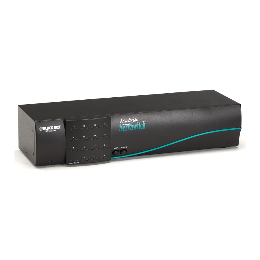
Page 17: The Front Panel
The Switch’s front panel features two pushbutton switches and several LED indicators. To familiarize yourself with these controls and indicators, refer to Figure 2-1 and the descriptions that follow on the next page. Power Figure 2-1. The front panel of a 2 x 16 Matrix ServSwitch (SW743A-R3). - Page 18 Panel Label Description POWER (left) Main Power LED: Lights to indicate that the Matrix ServSwitch is powered ON. [Numbered] CPU Status LEDs: Numbered pairs of LEDs indicate the status of the CPU connected to the corresponding port on the rear...
-
Page 19: The Rear Panel
All cable connections are made at the Switch’s rear panel, as illustrated in Figures 2-2 and 2-3 and described below and on the next page. Figure 2-2. The rear panel of a 2 x 16 Matrix ServSwitch with an Expansion Figure 2-3. The same rear panel, board and port numbering shown. -
Page 20: Power Input
INPUT] Description Connect the sharing computers to these ports with CPU Cables. At the Matrix ServSwitch end, these cables have a DB25 male connector; at the other ends, they have appropriate connectors to plug into your CPUs’ video, keyboard, and mouse ports. -
Page 21: Equipment Requirements
(greater than 640 x 480) video. 2.6 Equipment Requirements If the CPUs you will be controlling through your Matrix ServSwitch are not all of the same type—especially if you’re using multiplatform Switches and the CPUs represent completely different hardware platforms (IBM, Sun, etc.)—you will have to be careful to choose a common monitor, keyboard, and mouse that adequately support all of the CPUs. -
Page 22: Installation And Preconfiguration
3. Installation and Preconfiguration 3.1 Quick Setup Guide Figure 3-1 shows a basic example of taking a Matrix ServSwitch and connecting it to a CPU, a user station (monitor, keyboard, and mouse), another Switch, and AC power. IBM PC equipment is shown, but the principles will be similar for all equipment types. -
Page 23: Guidelines For Using The Matrix Servswitch With Your Equipment
CPUs, the Matrix ServSwitches to which they are connected should already be ON. (You should be able to freely disconnect and reconnect the mouse or keyboard from a Matrix ServSwitch while the Switch is ON, but if you experience problems when you do this, issue the Reset command [CTRL] R—see Section 6.11.) - Page 24 Other concerns: • The Matrix ServSwitch emulates several types of mice for the attached computers, but the actual mice used at your user stations must be the same type as the stations’ keyboards: Sun mice with Sun keyboards or PS/2 mice (not serial mice) with PC type keyboards.
- Page 25 MATRIX SERVSWITCH™ • The Matrix ServSwitch is designed to support IBM PC compatible 101-, 102-, 104-, or 105-key keyboards and IBM PC keyboard-scan modes 1, 2, and 3; it’s also designed to work with PC-type CPUs/keyboards that use 5-pin DIN or 6-pin mini-DIN keyboard connectors.
- Page 26 Table 3-1. Keyboard mapping by the Matrix ServSwitch. Generally, the Matrix ServSwitch interprets keys by their positions on the keyboard, so any keys that occupy more or less the same positions and perform more or less the same functions across platforms will map one-to-one. However, certain keys available on certain keyboards do not correspond well or are not available on other types of keyboards, so the Switch maps the more important of these as shown below.
-
Page 27: Monitor
CPUs to your system, either your monitor must be capable of accepting both H/V and composite-sync input, or you’ll have to use a sync converter and special cables to convert H/V to composite sync or vice versa (call Black Box Technical Support for a special quote). - Page 28 Matrix ServSwitches between the CPU and monitor, video quality will always be lower. This table also applies to Mac video in Matrix ServSwitch systems in which the Mac version of the original Serv type CPU Cable (product code EHN215) has been installed.
- Page 29 CPU to the monitor. Also as before, the table assumes a single Matrix ServSwitch is between the CPU and monitor; if there are other chained Switches as well, video quality will always be lower. (Where “interlaced” or “noninterlaced”...
-
Page 30: Installation Procedure
3.3.1 P LACEMENT The Matrix ServSwitch is best located as close as possible to the CPUs that are attached to it. This reduces the length of CPU cables and provides a more cost- effective, neater installation. You should also place the Switch as close as possible to the AC outlet you want to plug it into. - Page 31 2 x 8 Matrix ServSwitches is RMK19B, RMK23B, or RMK24B respectively. Our product code for a 19", 23", or 24" Kit that fits the 2 x 16 Matrix ServSwitch is RMK19C, RMK23C, or RMK24C respectively. See Appendix F for more information.
-
Page 32: Connecting Cpus
CPUs are Mac type, you’ll need multisync monitors at your user stations.) 5. If all of the CPUs you will be attaching to your Matrix ServSwitch system are Sun models, and none of the monitors you want to use support 640 x 480 resolution: Take the CPU Cable attached to the Switch’s lowest-numbered CPU port. - Page 33 Switch in the chain either before or as you install it, rather than installing everything and then working on the entire chain; see Section 3.6. Before installing an advanced configuration, please call Black Box and discuss your application with a technician.
- Page 34 640 x 480 (see step 5 in Section 3.3.5)—take the power cord of a Matrix ServSwitch in your system and plug the cord’s IEC 320 female outlet end into the Switch’s rear-mounted IEC 320 male power inlet. Then plug the other end of the cord into a working outlet.
- Page 35 (not the numeric keypad) and press [Enter]. Or, to review the configuration settings of your Matrix ServSwitch system, press and release left [Ctrl] followed within two seconds by the [F12] key; this will bring up the Switch’s on-screen display (see Chapter 4).
-
Page 36: Daisychaining Matrix Servswitches
RING (see Section E.1 of Appendix E). If you’re very careful, you can attach Matrix ServSwitches to daisychains of ServSwitch Affinity (product code KV13xA) chassis. See the “Mixed Chains” section of the Affinity manual for details, and please call Black Box Technical Support before installing such a mixed daisychain. -
Page 37: Topologies
3.4.2 T OPOLOGIES A standard Matrix ServSwitch system can support two independent users, but each of the user stations has to be attached to a different- numbered KVM port (one to KVM 1, the other to KVM 2), even if the stations are attached to different Switches. - Page 38 Unit 3: CPUs 33 to 48 Cable runs from OUT on Unit 1 to IN on Unit 3 Unit 2: CPUs 17 to 32 Unit 1: CPUs 1 to 16 Use a ring arrangement if you have user stations attached to two different Matrix ServSwitches and you want both of the users to have access (or at least potential access) to all CPUs.
-
Page 39: The Power-Up Procedure
MATRIX SERVSWITCH™ 3.5 The Power-Up Procedure About three seconds after you plug in and turn on a Matrix ServSwitch as described in Section 3.3.7, a diagnostics screen running a self-test will appear on user-station monitors and serial devices attached to the Switch. (In an all Sun installation with a monitor that doesn’t support 640 x 480 resolution, the video... - Page 40 3.5.1 T OWER IAGNOSTIC The diagnostic screen that appears when you turn ON the Matrix ServSwitch is shown in Figure 3-5; standard messages you might see on it are shown in Table 3-4 on the next page. Welcome to Matrix ServSwitch...
- Page 41 MATRIX SERVSWITCH™ Table 3-4. The standard diagnostic-screen messages. Diagnostic Messages Kernel Version Overlay Version Kernel Program Static RAM Configuration Board Number Communication ID Communication Local Ports Program Version Main Program Description Indicates version ID of kernel program being run by the Switch’s bottom port board (all of the port boards...
- Page 42 RROR The following messages may appear in the on-screen display (or, in the case of the Kernel Error message, instead of the on-screen display) during the Matrix ServSwitch’s power-up sequence. The meanings of “Main Program,” “Static RAM,” “Configuration,” and “Communication” are spelled out in the table on the previous page; the other parts of these messages are discussed on the following pages.
- Page 43 Unit halted Refer to operation manual or call technical support The error is major and has forced the kernel to stop processing. The Switch will have to be serviced. Call Black Box Tech Support as directed in Sections 8.2 and 8.3.
- Page 44 Unknown error Indicates faulty communication hardware. Try cycling power to the Matrix ServSwitch to see if this message goes away. If it doesn’t, the Switch will have to be repaired or replaced; call Black Box Tech Support as described in Sections 8.2 and 8.3.
- Page 45 ERNEL ERIAL The Matrix ServSwitch’s kernel writes this message to the serial port at power-up: Hit space bar within 5 seconds to get serial options menu If the Switch receives a [Space] character at the serial port during the next 5 seconds, the standard Matrix ServSwitch initialization terminates after writing the Local ports diagnostic message (see Section 3.5.1), and a serial options menu...
-
Page 46: Initial Configuration
3.6 Initial Configuration Once you plug in and turn on a Matrix ServSwitch and it passes the power-up diagnostic tests, you’ll need to set an important initial configuration parameter for it. You’ll be able to fully configure all of the Switches in your system later from a single user station, but it’s very important for your system operation that each... - Page 47 [Enter]. 2. Verify the “Starting computer number,” the system-sequence number that has to be assigned to the first CPU port on each Matrix ServSwitch. This setting must be unique for each Switch in a daisychain. The starting computer number for the first Switch should always be “1.” The starting number for the second Switch should be “total CPU ports on the first Switch plus one,”...
- Page 48 Table 3-5. Starting computer numbers and maximum computer in a sample Matrix ServSwitch Unit Number Maximum computer (sum) = 44 CHAPTER 3: Installation and Preconfiguration four-unit daisychain. Switch CPU Ports Model 2 x 4 2 x 16 2 x 8...
-
Page 49: Full Configuration
MATRIX SERVSWITCH™ 4. Full Configuration Once your Matrix ServSwitch system is up and running, you can configure the system from any attached user station (monitor, keyboard, and mouse). To do so, press and release the left [Ctrl] key, then press the [F12] key to access the configuration-menu screen shown in Figure 4-1. -
Page 50: Using The Menu
4.1 Using the Menu 4.1.1 N AVIGATING THE ONFIGURATION A help line at the bottom of each screen explains what each selection does. From the configuration main page, use arrow keys to highlight the desired configuration menu, and press the [Enter] key. New text or numeric values may be entered in an input box, or a list of possible choices will appear. -
Page 51: Saving Configuration Changes
MATRIX SERVSWITCH™ Matrix ServSwitch version MX16H Copyright 1990-2000 Main menu Configure System System Computer User Profile Group Status Save Exit Use arrow keys to highlight selection and press enter or press escape to exit Configure password box numbers, keyboard settings, appearance Figure 4-2. -
Page 52: Configuring The System
Switch. Factory default is no password. Don’t lose or forget your configuration password, or you will have to reset the Matrix ServSwitch to its factory defaults and all configuration information will be lost. - Page 53 (For example, if a Matrix ServSwitch system consists of one 2 x 8 Switch and two 2 x 16 Switches, set maximum computer to 8 + 16 + 16 = 40.) See Table 3-5 in Section 3.6.2 for the maximum computer value of a sample system.
-
Page 54: Appearance
Screen saver time Determines the period, in seconds, of keyboard and mouse inactivity before the Matrix ServSwitch activates the screen saver. Value may be from 0 to 9999 seconds. Entering 0 disables the screen saver. Factory default is 1200 seconds (20 minutes). - Page 55 Matrix ServSwitch to its factory defaults to get the window to reappear.) Factory defaults are solid cyan for the background color and black for the text color.
-
Page 56: Configuring Computers
[Computer Number] The numbers in this unlabeled field represent the CPU port in the Matrix ServSwitch system assigned to each computer. This value isn’t changeable through this menu; the Switch system will automatically calculate it based on the chassis’ starting computer number and the number of the physical CPU port that the computer is attached to. - Page 57 MATRIX SERVSWITCH™ Keyboard Use this field to assign one of the following keyboard modes. • PC1: PC mode 1. Appropriate for most IBM compatible PCs that do not use mode 2; in particular, several PS/2 models. • PC2: PC mode 2. Appropriate for the vast majority of IBM compatible PCs.
-
Page 58: Configuring User Stations
Here are the station-configuration parameters: The “ID” field contains the unique “communication ID” number assigned to the user station in the Matrix ServSwitch system. This value isn’t changeable through this menu; the Switch system will automatically calculate it based on the chassis’... - Page 59 Use this field to assign a name up to 16 characters long to either user (KVM) station on the Matrix ServSwitch. Factory defaults are “KVM Station 1” and “KVM Station 2” (with spaces embedded between the word “Station” and the number).
-
Page 60: Configuring User Definitions
(see Section 4.3), users must enter their usernames and passwords to log into the Matrix ServSwitch system. Passwords can be up to 8 characters long and are case-sensitive. Passwords are not shown when you type them in the password field. -
Page 61: Configuring User Profiles
Profile Use this field to assign users to “user profiles,” which are definitions of how users can access the Matrix ServSwitch system. Profiles are configured on the Configure Profile page (see Section 4.6). The factory-default profile for each user is the profile appearing in the same- numbered row in the “Configure Profile”... - Page 62 Here are the profile-configuration parameters: Name Use this field to assign a name up to 8 characters long to each user profile. This can be, for example, a descriptive term such as “Staff” or the name of a person or an area of business.
- Page 63 CPUs (see Section 6.15), the scan rate is the length of time that the Matrix ServSwitch shows each computer’s video on the user’s screen before changing to the next computer in sequence. Be careful: It is possible to set the scan rate low enough that a slower-synchronizing monitor may not display any video at all.
-
Page 64: Configuring Groups
4.7 Configuring Groups You can use the “Configure Group” page to assign computers to specific groups. Users that belong to a certain group can access computers that belong to the same group. Configure Group Computer Computer 2 Computer 3 Computer 4 Computer 5 Computer 6 Computer... - Page 65 MATRIX SERVSWITCH™ Group Name Group names are displayed above the group-membership indicators (plus signs). To change a group’s name, use arrow keys to move the highlight to the group’s column and press [Enter]. A box will appear beside the page; type a new name in this box and press [Enter] again.
-
Page 66: The Status
4.8 The Status Page This page displays status information for each port board (set of four CPU ports) in the Matrix ServSwitch system. This information is an invaluable tool when expansion or reconfiguration is necessary. Status Computers Power Slot Ver KVM... -
Page 67: Mouse And Keyboard
MATRIX SERVSWITCH™ Displays last three characters of the version ID of the main program in the board’s firmware. The last four fields apply only if (a) the port board is one of the bottom two on a Switch and thus includes a KVM port, and (b) there is a user (KVM) station attached to that KVM port: This field indicates the type of mouse and keyboard detected for that station. -
Page 68: On-Screen Functions, Same-Port Users, And Connection Modes
CPUs they select. 5.1 Logging In The Matrix ServSwitch system can be configured to require users at any user (KVM) station to type in a username and password in order to log into the system. -
Page 69: Connection-Status Messages
MATRIX SERVSWITCH™ 5.2 Connection-Status Messages A connection-status message provides information about a connection between a KVM station and a selected computer. There are three types of these messages: • “Connection successful” message • “Connection failed” message • Disconnect-status message The user-station (KVM) name, computer name, and username are displayed in each type of message. - Page 70 CHAPTER 5: On-Screen Functions, Same-Port Users, and Connection Modes Table 5-1. Reasons for connection failure. Reason Description Unable to communicate Can’t find computer with the Switch that the computer you’re trying to select is attached to. Another user is connected Computer is private to that computer in private...
-
Page 71: Disconnect Status
MATRIX SERVSWITCH™ 5.2.3 D ISCONNECT TATUS You may be disconnected from a selected computer in the middle of an activity, depending on how your system is configured. For instance, when a private-mode user connects to a computer, another user connected to the same computer receives a disconnect-status message labeled “Private mode cancel.”... - Page 72 CHAPTER 5: On-Screen Functions, Same-Port Users, and Connection Modes Table 5-2. Reasons for disconnection. Reason Description Response to a logout User request ([Ctrl][L]) or disconnect ([Ctrl][Q]) command. Communications error No response during disconnection. A private-mode user has Private mode cancel connected to the computer you had selected.
-
Page 73: User Stations Attached To Same-Numbered Ports
MATRIX SERVSWITCH™ 5.3 User Stations Attached to Same-Numbered Ports When there are no more than two users in a Matrix ServSwitch system, both of these users have completely independent global access: that is, each of them can reach any computer in the system, and their actions have no effect on each other, unless one tries to select the same CPU that the other is using (see Section 5.4). - Page 74 1. You can purchase one or more ServSwitch Affinity units. These are extremely similar to the Matrix ServSwitches, but they support as many as sixteen fully independent global users.
-
Page 75: Connection Modes
MATRIX SERVSWITCH™ 5.4 Connection Modes The Matrix ServSwitch has four “connection modes” that can be assigned to user profiles in order to give users with varying security clearances the corresponding level of access to the computers in the system. These connection modes, discussed in the following four subsections, are: •... -
Page 76: Private Mode
CHAPTER 5: On-Screen Functions, Same-Port Users, and Connection Modes 5.4.4 P RIVATE A private-mode user connects to a computer knowing that, while they are connected to that computer, no other user may access that computer in any way, even to view the computer’s screen. Non-private users already connected to a computer are immediately disconnected when a private user connects. -
Page 77: Command Summary
MATRIX SERVSWITCH™ 6. Keyboard Commands This chapter covers the keyboard commands that can be sent to the Matrix ServSwitch: Section 6.1 explains how to enter commands and lists all of the available commands. Sections 6.2 through 6.17 describe the commands more fully. - Page 78 Table 6-1 (continued). The Matrix ServSwitch’s keyboard commands. Command Keystroke Sequence Switch to the [Ctrl] [←] Prior Port [Ctrl] [Backspace] Toggle Station- [Ctrl] D Status Display Log Out [Ctrl] L Disconnect [Ctrl] Q Reset [Ctrl] R Keyboard and Mouse Reset Mouse...
-
Page 79: Display Configuration Menu: [Ctrl] [F12]
This command (press and release left [Ctrl], then press and release the escape key [Esc]) causes the Matrix ServSwitch to display, as shown below, a list of all CPU ports attached to the system—at least all of the ones whose CPU numbers are less than the system’s current “Maximum computer”... -
Page 80: Switch To The Previous Port In Sequence: [Ctrl] [–]
CHAPTER 6: Keyboard Commands 6.4 Select Computer: [Ctrl] xxxx [Enter] You can use this command (press and release left [Ctrl], then press and release each of the numeric digits of the port number, then press and release [Enter]) as a shortcut for directly selecting computers instead of doing so through the CPU list. -
Page 81: Display User-Station Status: [Ctrl] D
(b) you need to send mouse data to the CPU, but it hasn’t enabled the mouse (this can happen if you boot up the CPU while the Matrix ServSwitch is off or disconnected), or (c) while using a PS/2 type mouse, you unplug it, plug it back in, then have problems. -
Page 82: Reset/Enable Mouse In Windows Nt And Unix: [Ctrl] O
Windows NT or any variant of UNIX. When you press and release left [Ctrl], then press and release the letter [O] key, the Matrix ServSwitch sends “reset codes” to the PS/2 mouse port of the currently selected CPU. This will cause the CPU to reinitialize its Windows NT or UNIX mouse driver, which will reset or re- enable the mouse. -
Page 83: Identify Firmware Revision: [Ctrl] I
You can set the length of time that the Matrix ServSwitch pauses at each computer independently for each user profile (see Section 4.6). Any keystrokes and mouse input you enter during a scan are directed to the computer you are currently viewing, if no one else is using it and if you have higher than “view mode”... -
Page 84: End Scan: [Ctrl] X
For example, if you select a ServSwitch™ Ultra attached to CPU port 12 on a Matrix ServSwitch, and you want to switch to CPU port 3 on the Ultra, you can’t just type in left-[Ctrl] 3 [Enter], because the Matrix Switch will switch to its CPU 3 port. -
Page 85: Using The Serial Ports
• Restore factory defaults. 7.1 Basic Setup: Establishing a Serial Connection In order to access the serial ports of a Matrix ServSwitch, you’ll need these things: • A straight-through-pinned, flat-satin or twisted-pair serial cable with modular RJ-11 (4-pin) or RJ-12 (6-pin) connectors. (One of these is included with your Switch.) -
Page 86: The Serial Options Menu
Once you have connected the dedicated terminal or computer running a terminal emulator to one of the Matrix ServSwitch’s serial ports, make sure the data rate of the terminal or emulator is set to match that of the Switch port. (If you’re not sure how to do this for your emulator, refer to its manual or online help for instructions. -
Page 87: Option 1. Change Starting Computer
Change the setting of this option to change the baud rate (data rate) of the Matrix ServSwitch port board you are communicating with. Before you select it, this option will show the current speed of the port board’s serial port as either “9600”... -
Page 88: Option 3. Receive New Kernel Or Main Program (Upgrade Firmware)
Black Box Tech Support. To download a flash-upgrade file from the computer to the Matrix ServSwitch port board you’re communicating with, press 3 at the serial options menu. This message will appear: Waiting for file... - Page 89 If reprogramming seems to succeed, the procedure is finished if you’re using a single 2 x 4 Matrix ServSwitch, which only has one port board. But if you’re using a daisychained system with more than one Switch, or even if you’re using a single...
-
Page 90: Options 4 And 5. Send Main Program/Send Kernel
Switches, make sure all Expansion Modules and cables are firmly seated, and press 4 or 5 again. If there is still a mismatch, call Black Box for technical support. But if the number of port boards is now correct, reply with “Y.” This message will appear: Sending flash program code to system... -
Page 91: Option 6. Reset To Factory Defaults
PTION HANGES Use this option to save the configuration changes made in menu items 1 and 2 to the Matrix ServSwitch port board you’re communicating with. Press 7 at the serial options menu; this message will appear: Flash programming... When the procedure is complete, you will see this message and then be returned... -
Page 92: Option 8. Exit And Restart Unit
XIT AND ESTART To exit the serial options menu, press 8. The Matrix ServSwitch will reinitialize itself and launch its self-diagnostics program. If it passes its diagnostic tests, the Switch should be operational and ready for use; alternatively, if you have more... -
Page 93: Troubleshooting
8. Troubleshooting The first section of this chapter, Section 8.1, discusses things to try when problems arise in a Matrix ServSwitch system. Sections 8.2 and 8.3 discuss what’s involved in calling Black Box and shipping your Switch. 8.1 Common Problems It might be possible—although this is unlikely—to resolve some... - Page 94 A. Can you do anything from the keyboard? If not, the keyboard connector of your User Cable has probably come loose. Reconnect it. B. Are you trying to reach a computer on a remote Matrix ServSwitch? The port might be busy; try again later. If repeated attempts are unsuccessful, make sure that the Expansion Cables running to that Switch haven’t come loose and that the...
- Page 95 C. PS/2 or PS/2 wheel mouse: To recognize the mouse, the CPU must be directly connected to it, or indirectly connected to it through the Matrix ServSwitch, at boot-up time. Make sure that all cables are properly seated and that the Switch and submaster are ON, then reboot the CPU.
- Page 96 A under the section on the previous page headed “An IBM compatible computer’s mouse driver doesn’t load,” chances are that the Matrix ServSwitch doesn’t support it. B. If your mouse is a Microsoft BallPoint, you need the latest version of the Microsoft mouse driver.
- Page 97 F. If swapping cables doesn’t solve the problem, try plugging the CPU into a different CPU port on the Matrix ServSwitch. If the problem goes away when the CPU is connected to a different port, the old port is probably defective.
- Page 98 The Matrix ServSwitch doesn’t work with your dongle-protected software. The Matrix ServSwitch does not support most dongles (the devices required to be inserted into the keyboard line by some software for copy protection). The Matrix ServSwitch doesn’t work with your IBM ThinkPad.
-
Page 99: Calling Black Box
MATRIX SERVSWITCH™ 8.2 Calling Black Box If you determine that your Matrix ServSwitch is malfunctioning, do not attempt to alter or repair the unit. It contains no user-serviceable parts. Contact Black Box Technical Support at 724-746-5500. Before you do, make a record of the history of the problem. We will be able to... -
Page 100: Appendix A: Nvram Factory Defaults
Appendix A: NVRAM Factory Defaults The table below and on the next page shows the Matrix ServSwitch’s factory-default configuration options. To reload these values, you’ll need to access the Switch’s serial options menu (see Chapter 7). Option System Configure password...None Starting computer number...1... - Page 101 MATRIX SERVSWITCH™ Option Profile Name ...Profile n (n - profile number) Access ...From “Name” in Group page Connect...Share (share mode) Share (share-mode timeout) ...2 seconds Scan (scan rate) ...5 seconds Logout (logout timeout) ...240 minutes (4 hours) Group Membership...All computers belong to all groups Name ...Group n (n = group number)
-
Page 102: Appendix B: Cable Product Codes
The table below and on the following pages lists the product codes for all the types of cables we currently offer for use with the Matrix ServSwitch. The four digits that follow the dash in each product code indicate how long each cable is in feet (one foot = 30.5 cm). - Page 103 SGI (13W3 male) IBM PS/2 (6-pin mini-DIN male) *A ServSwitch Micro Mac Converter (KV99MCON) must be used with any of these cables. A Mac Video Adapter for ServSwitch (KV99MA) will also be required if the Mac CPU outputs non-VGA-compatible video.
- Page 104 4-User Matrix ServSwitch Expansion Cable: KV140www, where “www” = 010, 020, 035, 050, or 100 8-/16-User Matrix ServSwitch Expansion Cable: KV180www, where “www” = 010, 020, 035, 050, or 100 6-wire straight-through-pinned flat-satin cable with RJ-12 connectors for communicating with Matrix ServSwitch through its RS-232 ports: EL06MS-MM (specify length) Station Extender Kits (include local and remote modules and PVC: EHN250-0zzz, where “zzz”...
-
Page 105: Appendix C: Pinout Of Serial Ports
MATRIX SERVSWITCH™ Appendix C: Pinout of Serial Ports The table below shows the pinout of the Matrix ServSwitch’s RJ-12 (“6-wire RJ-11”) female RS-232 serial ports. Signal Name Data Set Ready Data Terminal Ready Transmit Data Signal Ground Receive Data Request to Send Abbrev. -
Page 106: Appendix D: The Lk461 Keyboard
Some of the computers manufactured by Compaq Corporation come with a special keyboard called the DEC LK461. The Matrix ServSwitch supports this keyboard by passing through unaltered the scan codes of certain proprietary keys (such as [Help] and [Do]) and remapping others (such as [PF1] through [PF4]). -
Page 107: E.1 Setting The Ring/Bus Jumper (Jumper Jp1 On Expansion Modules
E.1 Setting the RING/BUS Jumper (Jumper JP1) on Expansion Modules Before you install Expansion Modules (our product code SW740C-R3-B) in a daisychained Matrix ServSwitch system, you might need to set their RING/BUS jumpers. If the daisychain is laid out in a bus topology (see Section 3.4.2), you won’t need to set them—skip ahead to Section E.2. -
Page 108: E.2 Swapping In An Expansion Module
E.2 Swapping In an Expansion Module Making sure that the Matrix ServSwitch is turned OFF and unplugged, unscrew and remove any blank plate over the opening of the Matrix ServSwitch’s Expansion slot. (You should always have a plate covering this slot when a Terminator Module is in it. -
Page 109: E.3 Swapping In A Terminator Module (Not Recommended)
MATRIX SERVSWITCH™ E.3 Swapping In a Terminator Module (Not Recommended) It should never be necessary to swap a Terminator Module back in for an Expansion Module; the Expansion Module can terminate a non-daisychained Switch. But if you ever need to do this for whatever reason, your first step should be to unscrew the Expansion Module and gently remove it from the slot, as shown at the top of Figure E-3. -
Page 110: Appendix F: Rackmounting The Matrix Servswitch
Rackmounting the Matrix ServSwitch You can use a ServSwitch Rackmount Kit to mount a Matrix ServSwitch in a 19", 23", or 24" rack. Use the RMK19B, RMK23B, or RMK24B Kit respectively to mount a 2 x 4 or 2 x 8 Switch; use the RMK19C, RMK23C, or RMK24C respectively to mount a 2 x 16 Switch. - Page 111 MATRIX SERVSWITCH™ To use a Kit to mount a Matrix ServSwitch, take these steps, referring to Figure F-1: 1. Match up the two holes in the “Switch end” of each Kit ear with the two empty screwholes on the side of the Switch, then fasten the ear to the Switch with two of the screws included with the Kit.
- Page 112 NOTES...
- Page 113 NOTES...
- Page 114 NOTES...
- Page 115 NOTES...
Need help?
Do you have a question about the ServSwitch and is the answer not in the manual?
Questions and answers