Table of Contents
Advertisement
Quick Links
Advertisement
Table of Contents

Related Manuals for DSC IoTega


Summary of Contents for DSC IoTega
-
Page 1: User Manual
IoTega Self-Contained Wireless Security System User Manual WARNING: This manual contains information on limitations regarding product use and function and information on the limitations as to liability of the manufacturer. Read the entire manual carefully. -
Page 2: Table Of Contents
Table of Contents 1.0 About Your Security System 1.1 Fire Detection 1.2 Carbon Monoxide Detection 1.3 Testing 1.4 Monitoring 1.5 Maintenance 2.0 General System Operation 2.1 Integrated Keypad 2.2 Panel Indicators 2.3 Important Notice 2.4 Language Selection 2.5 System Models 3.0 Arming the System 3.1 Stay Arming 3.2 Silent Exit Delay 3.3 Away Arming 3.4 Quick Exit 3.5 Arming Errors and Exit Faults 3.5.1 Arming Error 3.5.2 Audible Exit Fault 3.6 Alarm Cancel Window 3.7 Bypass Zones 3.8 Bypass Group 4.0 Disarming the System 4.1 Disarming Error 5.0 Using Wireless Keys 6.0 User Access Codes 6.1 Access Code Types 6.2 Level 1 Access (Supervisor/Administrator) 6.3 Level 2 Access (Basic/Standard User) 6.4 Level 3 Access (Maintenance/Guest) 6.0 Additional Features 6.5 Burglary Verification 6.6 Swinger Shutdown 6.7 Fire Alarm Verification 7.0 Emergency Keys 7.1 Two-Way Audio Operation 7.2 Intrusion (Burglary) Alarm Continuous Siren 7.3 When Alarm Sounds 7.4 Fire Alarm Pulsed Siren (Temporal 3) - Page 3 8.7.2 Viewing Live Video and Recordings 8.8 Setting Event Recordings 8.9 Creating an Event Schedule 8.10 Creating Scenes 8.11 Running a Scene 8.12 Controlling Lights and Appliances 8.13 Controlling a Thermostat 8.14 Managing Notifications 9.0 Using Z-Wave Devices 9.1 Z-Wave Alliance Certification 9.2 Adding or Removing a C ontroller 9.3 Replicating a Controller 9.4 Controller Learn Mode 9.5 Changing the Primary Controller 9.6 Adding a D evice 9.6.1 Editing or Removing a D evice 9.7 Device Interoperability 9.8 Z-Wave Association Groups 9.9 Z-Wave Reset 10.0 Viewing Troubles on the Integrated Keypad 10.1 Alarm Memory 11.0 Testing Your System 11.1 System Test 12.0 Safety Instructions 12.1 Removing the Battery 12.2 Regular Maintenance and Troubleshooting 12.3 Cleaning and Maintenance 13.0 Locating Detectors and Escape Plan 13.1 Smoke Detectors 13.2 Fire Escape Planning 13.3 Carbon Monoxide Detectors 14.0 Installer Warning 14.0 Regulatory Agency Statements 15.0 Reference Sheets 15.1 System Information...
-
Page 4: About Your Security System
Chapter 1.0 About Your Security System 1.0 About Your Security System Read this manual carefully and have your installer instruct you on your system's operation and on which features have been implemented in your system. All users of this system should be fully instructed in its use. Fill out the System Information page with all of your zone information and access codes, and store this manual in a safe place for future reference. Note: The IoTega security system includes specific false alarm reduction features and is classified in accordance with ANSI/SIA CP-01-2014 Control Panel Standard - Features for False Alarm Reduction. Consult your installer for further information regarding the false alarm reduction fea- tures built into your system, as this manual does not cover all features. 1.1 Fire Detection This system can monitor fire detection devices, such as smoke detectors, and provide a warning if a fire condition is detected. Good fire detection depends on having an adequate number of detectors placed in appropriate locations. This equipment must be installed in accordance with NFPA 72 (N.F.P.A., Batterymarch Park, Quincey MA 02269). Carefully review the Family Escape Planning guidelines in this manual. Note: Your installer must enable and configure this feature. 1.2 Carbon Monoxide Detection This system can monitor carbon monoxide detectors and provide a warning if carbon monoxide is detected. Read the Family Escape Planning guidelines in this manual and the instructions for the car- bon monoxide detector. Note: Your installer must enable and configure this feature. 1.3 Testing Test your system weekly to ensure that your system functions as intended. Refer to the Testing your ... -
Page 5: Maintenance
Chapter 1.0 About Your Security System 1.5 Maintenance With normal use, the system requires minimum maintenance. Note the following points: Do not wash the security equipment with a wet cloth. Light dusting with a slightly moistened cloth removes normal accumulations of dust. Replace the standby battery every 3-5 years. WARNING! Do not attempt to replace the battery or open the enclosure, as there is a risk of elec- tric shock or fire. For other system devices such as smoke detectors, passive infrared, ultrasonic or microwave motion detectors, or glass break detectors, consult the manufacturer’s literature for testing and main- tenance instructions. - 4 -... -
Page 6: General System Operation
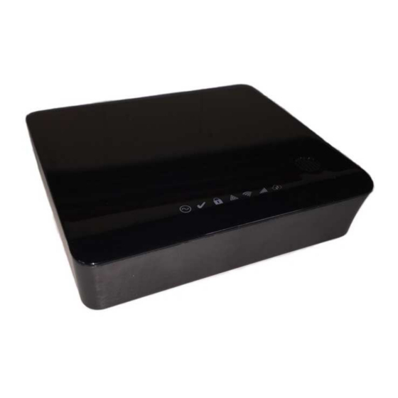
Chapter 2.0 General System Operation 2.0 General System Operation Your security system comprises an integrated alarm control/panel and various sensors and detectors. The panel is mounted by the main entry/exit location. The system is self-contained; electronics and standby battery are housed within the unit. Note: Ensure that only the installer or a service professional has access to the system. The security system has several zones of area protection. Each of these zones communicates to one or more wireless sensors, such as motion detectors, glass break detectors, door contacts, etc. A sensor in alarm is indicated by messages on the IoTega mobile phone user application. Additional features include Automatic Inhibit (Swinger Shutdown) for alarm, Tamper and Trouble signals after three occurrences in a given set period, and a programmable Keypad Lockout option. For SIA CP-01 classified installations, the swinger shutdown feature is programmed such that one or two trips shuts down the zone. The zone is restored after a manual reset by entering the access code at the time of disarming the alarm system, or it is reset automatically after 48 hours with no trips on any zones. Note: The mobile phone user application feature was not evaluated by UL/ULC. 2.1 Integrated Keypad The IoTega system includes a capacitive touch integrated keypad with 16 keys: numbers 0 thru 9, *, #, Fire, Auxiliary, Panic (FAP), and shift (up arrow). In normal operation, the keypad remains dim when not in use. When a user is in close proximity, the number keys illuminate. Note: The FAP keys do not illuminate unless the shift key is tapped. See the Emergency Keys sec- tion for more information. Note: The keypad can only be used for arming, disarming, and the local FAP. The same functions are available when switching between partitions. 2.2 Panel Indicators The IoTega system includes a series of illuminated point source status indicators. There is a min-... - Page 7 Chapter 2.0 General System Operation Item Description Power LED Ready to Arm LED Armed LED Trouble LED WiFi Signal Strength LED Cellular Signal Strength LED Remote Connection LED Power Status Light LED indicator Description ON Steady AC power is connected to the system. Flashing System Test All status LEDs flash at the same time. There is no AC or battery power to the system. Ready to Arm Status Light LED indicator Description...
- Page 8 Chapter 2.0 General System Operation Armed Status Light LED indicator Description ON Steady The partition is armed.. Flashing The system in Alarm. Note: Silent a larms or panic do not flash the Alarm LED. System Test All status LEDs flash at the same time. Installer Walk Test Ready, Trouble, and Arm LEDs flash at the same time. The partition is disarmed Trouble Status Light LED indicator Description ON Steady A system trouble is present. ...
- Page 9 Chapter 2.0 General System Operation Cellular Signal Strength Status Light LED indicator Description ON Steady ( green) Cellular is active with a strong s ignal con- nection. ON Steady ( yellow) Cellular is active with a weak s ignal con- nection. ON Steady (red) A communicator is installed but there is no signal or connection. Flashes red for a few seconds, System Test All status LEDs flash at the same time. then flashes green A communicator is not installed or not ...
-
Page 10: Important Notice
Chapter 2.0 General System Operation 2.3 Important Notice A security system cannot prevent emergencies. It is only intended to alert you and your central sta- tion, if applicable, to an emergency situation. Security systems are generally very reliable, but they may not work under all conditions and they are not a substitute for prudent security practices or life and property insurance. Your security system must be installed and serviced by qualified security professionals. These professionals can instruct you on the level of protection that has been provided and on system operations. Note: When the panel is in Sleep Mode, it is saving battery life. The panel will not be turned on until there is a specific reason, such as a hand wave in front of the panel, or the start of an entry delay. In this mode the keypad is still functioning and nothing will be visible; however if desired, your installer can enable the armed status to be visible while in Sleep Mode. 2.4 Language Selection The s ystem supports the following three languages: English French Spanish You can select the language on the touchscreen keypad. 2.5 System Models The reference to WS900 in this manual covers the following models: WS900-29* Alarm system with two-way audio support, operating in 912-919 MHz band WS900-19* Alarm system with two-way audio support, operating in 912-919 MHz band 3G Cellular Alarm Communicator 3G7090*... -
Page 11: Arming The System
Chapter 3.0 Arming the System 3.0 Arming the System You can arm the system using the following options: Integrated keypad Touchscreen keypad User app (Operation with the user app was not evaluated by UL/ULC.) Wireless key (Refer to section 5.0 for a list of UL/ULC listed compatible wireless keys.) 3.1 Stay Arming Stay Arming arms the perimeter of the premises while permitting movement inside. To arm the system in Stay mode, do the following steps: 1. Ensure all protected doors and windows are secure or bypassed and that the R eady indicator is on. 2. Enter a valid user code and do not leave the premises. The system automatically ignores bypassed zones and initiates the exit delay countdown. When exit delay is active , the Armed and Ready i ndicators turn on and the keypad is silent. When the exit delay expires, the system is armed and indicated by the following conditions on the keypad: The Ready indicator turns off. ... -
Page 12: Quick Exit
Chapter 3.0 Arming the System When the exit delay has expired, the system is armed and indicated by the following conditions: The Ready indicator turns off. The Armed indicator stays on. The keypad is silent. Note: In Away Arming mode, manually bypassed zones are logged and communicated to the cent- ral station. If your system is installed in accordance with SIA CP-01 Standard for False Alarm Reduction, the following condition applies: Violation and restoral, followed by a second violation of the entry/exit zone before the end of the exit delay, restarts the exit delay. Note: This function is available on the touchscreen keypad and user app. 3.4 Quick Exit If the system is armed and you must exit, use the Quick Exit function to avoid disarming and rearm- ing the system. Using this function gives you 2 minutes to exit the premises. When the door is closed after exiting, the remaining exit time is cancelled. 3.5 Arming Errors and Exit Faults Your security system audibly notifies you of any errors when you are attempting to arm the system or exit the premises. 3.5.1 Arming Error An error tone (long beep) sounds if the system is unable to arm. Arming errors occur under the fol- lowing conditions: The system is not ready to arm, i.e. sensors are open The entered user code is incorrect. ... -
Page 13: Bypass Zones
Chapter 3.0 Arming the System 3.7 Bypass Zones Use the zone bypassing feature when you need access to a protected area while the system i s armed, or when a zone is temporarily out of service, but you need to arm the system. Bypassed zones are not able to sound an alarm. As a result, bypassing zones reduces the level of security. If you are bypassing a zone because it is not working, call a service technician immediately to resolve the problem an restore your system to proper working order. Ensure that no zones are unintentionally bypassed when arming your system. Zones cannot be bypassed once the system is armed. Bypassed zones, except for 24-hour zones, are automatically cancelled each time the system is disarmed and must be bypassed again before the next arming. Note: Two-hour zones can only be unbypassed manually. This function is available on the touchscreen keypad and user app. For UL listed installations, zones can only be bypassed manually. To bypass an active zone on the touchscreen keypad or user app, do the following steps: 1. Tap the main menu icon to access the main menu. 2. Tap Sensors. 3. Slide the switch from right to left to bypass the active zone. 3.8 Bypass Group A bypass group is a selection of zones programmed into the system. If you bypass a group of zones on a regular basis, you can program them into a bypass group, so that you do not have to bypass each zone individually. Note that you can only program one bypass group at a time. ... -
Page 14: Disarming The System
Chapter 4.0 Disarming the System 4.0 Disarming the System You can arm the system using the following options: Integrated keypad Touchscreen keypad User app (Operation with the user app was not evaluated by UL/ULC.) Wireless key (Refer to section 5.0 for a list of UL/ULC listed compatible wireless keys.) To disarm the system on the integrated keypad, do the following steps: 1. Enter your access code. 2. If you open the entry/exit door, a continuous tone indicates that entry delay has started. Enter y our access code within ____ seconds to avoid an alarm condition. Your installer can program this time. Note: When disarming the system during entry delay, the tone is silenced when you enter the first digit of your access code. If you enter an invalid access code, the tone starts again. 4.1 Disarming Error If your code is invalid, the system will not disarm and the system emits a 2-second error tone. If this happens, press [#] and try again. - 13 -... -
Page 15: Using Wireless Keys
5.0 Using Wireless Keys In addition to the keypad, you can control your system with two-way wireless keys. All wireless key buttons are programmable. Your installer can verify the functions for each key. Using a two-way wireless key, you can arm or disarm the system while you are in close proximity to your house, or you can call for help. The following wireless keys are compatible with the IoTega system: PG4929/PG8929/PG9929 PG4939/PG8939/PG9939 PG4949/PG8949/PG9949 1. Away Arm ... -
Page 16: User Access Codes
Chapter 6.0 User Access Codes 6.0 User Access Codes The IoTega system supports up to 100 users, including the Master user. By default, user #1 is the Master user. You cannot disable or delete this user from the system. The system also supports an additional two duress codes, one for each partition. From the touchscreen keypad and user app, you can program and configure attributes for users 2 thru 100. You can assign a user to one or both partitions and enable or disable system interaction. User codes are 4-digits and must be unique; the system does not recognize duplicate codes. If you program a duplicate code, the system errors and rejects the code. If you try to change an existing user code to a one that is already programmed, the system errors and rejects the change. Refer to the Managing Users section for more information. 6.1 Access Code Types The IoTega system provides the following user access code types: Master Code This is the system master code. You cannot disable or delete this code, but you can change it in the user app. Use this code to program all other access codes, including the duress codes. You can use this code to do all user-level functions, except to access Installer mode. User Codes There are three access levels for user codes: Level 1 - Supervisor/Administrator Level 2 - Basic/Standard User Level 3 - Maintenance/Guest Each level has different permissions. ... -
Page 17: Level 2 Access (Basic/Standard User)
Chapter 6.0 Additional Features Initiate firmware updates Update the system WiFi SSID and password Create new users and user labels Program duress codes Note: Users can only add, edit, or delete users that are assigned to the same partition as they are. 6.3 Level 2 Access (Basic/Standard User) Users at this level have access to basic security functions but are limited based on their partition assignment. Users can do the following actions on their partitions: Arm/disarm Bypass/unbypass Chime enable/disable View system troubles View alarm memory 6.4 Level 3 Access (Maintenance/Guest) Users at this level are limited to reduced system access on their partition assignment. Users can do the following actions on their partitions: Arm/disarm ... -
Page 18: Emergency Keys
Chapter 7.0 Emergency Keys 7.0 Emergency Keys IMPORTANT: EMERGENCY USE ONLY! The emergency keys generate a fire, auxiliary, or panic alarm and alerts the central monitoring sta- tion. To use the emergency keys, do the following steps: 1. Tap the shift key on the keypad. T he emergency keys illuminate. Fire Alarm Auxiliary Alarm Panic Alarm 2. Touch the Fire, Auxiliary, or Panic key for 2 seconds, as needed. The system beeps to indicate that the alarm input has been accepted and sent to the monitoring station. 3. To return to the number keypad without using the emergency keys, tap the [#] key. Note: Depending on your system configuration, your installer can disable any of the emergency keys. 7.1 Two-Way Audio Operation This feature is used to verify the nature of an alarm and to determine the type of assistance t he occupant needs. When the central monitoring station receives an alarm, they initiate a two-way audio s ession. Note: Only the central monitoring station can initiate a two-way audio session when they receive ... -
Page 19: When Alarm Sounds
Chapter 7.0 Emergency Keys If the alarm was accidental, enter your access code to silence the alarm. If the alarm system is dis- armed within the programmed transmitter delay time, no alarm transmission is sent to the central monitoring station. C heck with your installer to see if this option has been enabled on your system and for the transmitter delay time. Following the transmitter delay time, you have 5 minutes to enter your user code to cancel an alarm that has been previously transmitted. A cancel signal is sent to the central monitoring station and the system indicates that the cancel signal was transmitted. Call your central monitoring station to avoid a dispatch. 7.3 When Alarm Sounds The system can generate the three different alarm sounds in this order of priority: 1. Fire Alarm = Temporal/pulsed siren 2. Carbon Monoxide Alarm = four beeps, 5-second pause, four beeps 3. Intrusion (Burglary) Alarm = Continuous siren Note: The Auxiliary Alarm is silent and only results in an alarm transmission to the central mon- itoring station. 7.4 Fire Alarm Pulsed Siren (Temporal 3) In the event of a fire alarm, follow your emergency evacuation plan immediately! The fire alarm t emporal/pulsed siren sounds of three short pulses followed by a 1.5-second pause, then repeats. . If the fire alarm was accidental, e.g. burnt toast, bathroom steam, etc., enter your access code to silence the alarm and call your central monitoring station to avoid a dispatch. -
Page 20: Using The Smartlink User App And Web Portal
Chapter 8.0 Using the Smartlink User App and Web Portal 8.0 Using the Smartlink User App and Web Portal You can manage your s ystem with the Smartlink user app and web portal. Both provide access to several features on your system, including the following functions: Viewing the system status and activity Arming and disarming Bypassing zones Viewing the system status and troubles Managing devices and cameras The web portal includes all functions that are available on the app and additional functions, includ- ing the following: Setting event recordings Creating scenes ... -
Page 21: Account Lockout
Chapter 8.0 Using the Smartlink User App and Web Portal To edit a user account, click the Edit icon next to the user in the Contacts list. 8.2.1 Account Lockout You have three log-on attempts before your account is locked. When this happens, your IP address is blocked for 20 minutes. After that time, the account is unlocked and you can log on again. If you forget your password, you can avoid being locked out by resetting your password before your third log-on attempt. To reset your password, complete the following steps: 1. On the login screen, tap Forgot Password? Enter the following details, then tap Next: Username Phone number E-mail address An e-mail is then sent to your e-mail address with a link to reset your password. 8.3 App Main Screen The main screen of the Smartlink app shows the current system status and lists the options available to manage your system and connected devices. Icon Description Activity lists system, events, such as alarms, arming, disarming, and troubles. Lights &Appliances lists controllable Z-Wave devices, such as lights and switches, and ... -
Page 22: Security
Chapter 8.0 Using the Smartlink User App and Web Portal The main screen icons also appear in a footer navigation bar on most pages. Slide the bar left to right to see additional options. 8.4 Security The Security s creen includes functions and options for you to control your system. From this screen, you can access the following options: View current system status Arm or disarm the system Access zone options Silence the alarm Turn the entry delay ON/OFF Access door locks 8.4.1 Arming You can arm your system in Stay o r Away m ode from the Security screen. To arm the system, t ap the Stay or Away i con. When the exit delay expires, the system is armed and indicated by the Armed Stay or Armed ... -
Page 23: Viewing System Activity And Troubles
Chapter 8.0 Using the Smartlink User App and Web Portal 8.6 Viewing System Activity and Troubles The Activity s creen lists s ystem, events, such as alarms, arming, disarming, and troubles. Tap an event to see more information. 8.7 Adding a Camera The Smartlink user app supports SNET cameras only, from which you can monitor your system through live footage or recordings. You can add cameras on the app and in the web portal. Before you add a camera on the app, make sure your smartphone is connected to your home WiFi network. To add a camera, complete the following steps: 1. From the Settings screen, tap Add Camera and tap on the image that matches your camera. Enter a name for your camera. Tap Scan QR code to use your smartphone to scan the unique device ID on the camera. Alternatively, you can enter the ID manually. Enter the device ID, including dashes and char- acters, then tap Next. Plug the camera into a power outlet Use one of the following methods to connect your camera: ... -
Page 24: Editing Or Removing A Camera
Chapter 8.0 Using the Smartlink User App and Web Portal To use this option, w ait 90 seconds after connecting power to the camera, then tap Check Con- nection. WiFi via Soundwave (indoor cameras only) For indoor cameras, you also have the option to Connect via Soundwave. To use this option, hold your smartphone near the camera and make sure the volume on your phone is turned up. Your phone plays an audible sound and passes your WiFi network information to the camera. The WiFi indicator light flashes slowly while the camera is in listen mode. When the WiFi connection is successful, indoor cameras beep twice and the WiFi indicator light stays on. If using WiFi via IP, you can now disconnect the Ethernet cable. 8.7.1 Editing or Removing a Camera To edit a camera, complete the following steps: 1. From the Settings screen, tap Edit Camera and tap on the one you want to edit. Update the camera name and tap Done to save the changes. To remove a camera, tap Remove Camera. -
Page 25: Setting Event Recordings
Chapter 8.0 Using the Smartlink User App and Web Portal Rotate your phone horizontally to switch to full-screen viewing and to see the following video con- trols: Mute toggles on and off the volume through the camera. Microphone launches a Push to Talk button. Touch and hold the button to speak from your smartphone through the camera's built-in speaker. Recordings displays and overlay of the Constant and Event recordings. Control shows and overlay list of your device, which you can control while you are viewing live video. Snapshot saves an image of the current video frame to your smartphone. Pan/Tilt launches the pan and tilt overlay controls on supported cameras. For Constant recording playback, tap on a recording in the list to start playback of the video. Tap the screen to pause or continue playback, or drag the slider to a particular point in the video. You can choose another video from the recording list, or tap the Back icon to return to live view- ing. 8.8 Setting Event Recordings In the web portal, you can set your cameras to record certain events, such as alarms, arming and dis- arming, or scenes. To set an event recording, complete the following steps: 1. In the web portal, go to the Camera Settings page from the left side menu. Click the down arrow, then click Edit on the camera that you want to record. Click Edit again to see the camera settings. Check Enable record on arms and Enable record on disarms to start recording for those events. Check all the listed sensors under the Recording on Zones header to record alarm events when a sensor triggers an alarm condition. Note: Alarm events only record for sensors that you check on the Recording on Zones page. -
Page 26: Creating An Event Schedule
Chapter 8.0 Using the Smartlink User App and Web Portal 8.9 Creating an Event Schedule Event schedules are event-based triggers used to run scenes or individual devices automatically. You can create event schedules in the web portal. To create an event schedule, complete the following steps: 1. In the web portal, go to the Event Schedule page. Enter a name and choose a trigger type. Trigger types are as follows: Alarm events Time (one-time event or repeated) Individual zones Z-Wave devices When you select a trigger type, the page updates so you can select a specific device and condition for time, zone, alarm event, or just a device. In the Actions section, choose your desired devices and scenes and corresponding actions to run on this event schedule. Click Save to create and activate the event schedule. 8.10 Creating Scenes A scene is a group of device actions set to run collectively that can be triggered by an event sched- ule or on-demand from the app or web portal. You can create scenes in the web portal. ... -
Page 27: Running A Scene
Chapter 8.0 Using the Smartlink User App and Web Portal 8.11 Running a Scene You can run a scene on-demand from the app or the web portal. On the app, the Scenes screen con- tains your created scenes and system preset scenes such, All Lights, All Devices, or All Appli- ances. To run your created scene, tap the Play icon next to the scene name. To control a preset scene, use the slider or toggle switches next to the scene. 8.12 Controlling Lights and Appliances The Lights & Appliances screen lists your controllable Z- Wave devices, including lights and switches. Lights are devices with dimmer functionality. Use the toggle switch next to the device name, to turn the light on and off. Control the brightness of the light by using the slider under the device name. Appliances are devices that have only on and off capability, such as a smart switch. Use the toggle switch to turn the appli- ance on and off. - 26 -... -
Page 28: Controlling A Thermostat
Chapter 8.0 Using the Smartlink User App and Web Portal 8.13 Controlling a Thermostat The Thermostat screen shows the current temperature reading. Adjust the target temperature by tapping the up and down arrows. Tap on the Mode or Fan options to switch to Heat/Cool/Off mode and On/Auto fan. 8.14 Managing Notifications You can receive notifications for arming, disarming, alarms, and system events. To set your notifications, complete the following steps: 1. From the Settings screen, tap Notifications. Tap the toggle switch to turn all notifications on or off. To receive individual notifications, select the box beside that type. You can also manage notifications for each user in the web portal. To set notifications for a system user, complete the fol- lowing steps: 1. From the Contacts page, click the down arrow to expand the contact. Click the buttons for Text Alert and Email Alert to turn them on or off. - 27 -... -
Page 29: Using Z-Wave Devices
Chapter 9.0 Using Z-Wave Devices 9.0 Using Z-Wave Devices The Smartlink user app and web portal supports Z-Wave enabled devices, such as lights,, door locks, and switches. 9.1 Z-Wave Alliance Certification The IoTega panel is a security enabled Z-Wave Plus product that can use encrypted Z-Wave Plus messages to communicate to other security enabled Z-Wave Plus products. 9.2 Adding or Removing a Controller To add the panel as a secondary controller to another Z-Wave network, complete the following steps: 1. Put the primary c ontroller into Inclusion mode. R efer to the controller manual for more information. In the Smartlink web portal, under Home Control, click Device Control. Under Setup, click Tools, then click Add/Remove Z-Wave Controller. To remove the panel as a secondary controller and re-establish it as primary, repeat the steps, chan- ging the primary controller in step 1 to Exclusion mode. 9.3 Replicating a Controller If the panel is established as a secondary controller on the Z-Wave network, you can request rep-... -
Page 30: Controller Learn Mode
Follow the instructions onscreen to bind your device. R efer to the device instructions, if neces- sary. When enrollment completes, enter a device name and tap OK. Your device is ready to use. If using a Z-Wave smart switch to control power to a light or appliance, such as a fan, simply, plug it into an AC power outlet. Note: Only use the dimmer function on supported devices to prevent damage to the device. 9.6.1 Editing or Removing a Device To edit or remove a device, complete the following steps: 1. From the Settings screen, tap Edit Device, then select the device you want to edit or remove. Update the device name and tap Done to save your changes. Alternatively, tap Remove Device to remove it from your system. 9.7 Device Interoperability Your dealer can provide you with a list of currently supported Z-Wave devices. However, all Z- Wave Plus devices, supported and unsupported, are partially or fully operable. At a minimum, listen- ing nodes function as message repeaters. 9.8 Z-Wave Association Groups The IoTega panel supports association group 1 with up to 100 nodes. A ssociation group 1 notifies associated nodes of the device status. The panel sends a Z-Wave Basic Report as a bitmap with the following property values: Property Low Battery AC Failure - 29 -... -
Page 31: Z-Wave Reset
Chapter 9.0 Using Z-Wave Devices Property No Battery Tamper 9.9 Z-Wave Reset To remove all the Z-Wave devices and restore the Z-Wave controller to factory defaults, complete the following steps: In the Smartlink web portal, under Home Control, click Device Control. Under Setup, click Tools, then click Reset Z-wave. Note: Please use this procedure only when the network primary controller is missing or otherwise inoperable. - 30 -... -
Page 32: Viewing Troubles On The Integrated Keypad
Chapter 10.0 Viewing Troubles on the Integrated Keypad 10.0 Viewing Troubles on the Integrated Keypad When the system detects a trouble condition, the Trouble indicator turns on and the system beeps once every 10 seconds. T ap any key to silence the beeps. Note: For UL Listed installations, your access code is required to view system troubles. To view troubles on the integrated keypad, do the following steps: 1. When the keypad illuminates, tap [*][2]. 2. Enter your access code, if required. T he Trouble indicator flashes if an access code is required. The system indicates top-level trouble codes by illuminating the corresponding numbers on the keypad, and the Trouble indicator flashes once with a pause, then repeats. 3. Tap one of the numbers to see the next level code. A t the second level, the Trouble indic- ator flashes twice with a pause, then repeats. 4. Repeat step 3 to go to the next level. The system beeps if there is no third-level trouble condition. At this level, the Trouble indicator flashes three times with a pause, then repeats. -
Page 33: Alarm Memory
Chapter 10.0 Viewing Troubles on the Integrated Keypad Top Level Second Level Third Level Device Type Trouble Type Device ID Keypad AC (Power G only) 1 to 4 Battery Trouble (Power G only) Tamper (Power G only) Fault (supervision) ( Power G, WiFi keypads) Not Networked (Power G only) Repeater 1 to 8 Battery Trouble Tamper Fault ( supervision) Not Networked RF Jam Wireless key For future use 1 to 32 Battery Trouble Tamper ... -
Page 34: Testing Your System
Chapter 11.0 Testing Your System 11.0 Testing Your System Inform your Monitoring Station when you begin and end system testing. Household fire alarm systems shall be tested by a qualified service technician at least every 3 years in accordance with NFPA72. It is the user’s responsibility to test the system weekly (excluding smoke detectors). Ensure you follow all the steps identified in the following sections. Should the system fail to function properly, call your installer immediately for service. 11.1 System Test The system test activates a 4-second check of the system status indicators, keypad lights, buzzer, and siren. I t is a partition-based test must be done when the system is disarmed. To start a system test from the touchscreen keypad or the user app, do the following steps: 1. Tap the main menu icon to access the main menu. 2. Tap Advanced, then tap Execute System Test. The following conditions indicate a system test is in progress: All system status indicator lights flash for 4 seconds. A system test transmits to the central monitoring station The system checks the backup battery level. The keypad lights illuminate for 4 seconds. The system buzzer sounds for 4 seconds, or the partition buzzer and siren sound for 2 seconds each in series. -
Page 35: Safety Instructions
Chapter 12.0 Safety Instructions 12.0 Safety Instructions This equipment is DIRECT PLUG-IN. I t must be installed and used within an environment that provides the pollution degree max 2, over voltages category II, in non-hazardous, indoor locations only. WARNING! This equipment has no mains on/off switch; if the equipment must be quickly dis- connected, the plug of the direct plug-in power supply is intended to serve as the disconnecting device; it is imperative that access to the mains plug and associated mains socket/outlet, is never obstructed. When using equipment connected to the mains and/or to the telecommunication network, there are basic safety instructions that must always be followed. Refer to the safety instructions provided with this product and save them for future reference. To reduce the risk of fire, electric shock and/or injury, observe the following: Use authorized accessories only with this equipment! DO NOT leave and/or deposit ANY object on the top of the cabinet of this equipment! The cabinet i s not designed to support any supplementary weight! Do not touch the equipment and its connected cables during an electrical storm; there may be a risk of electric shock. Never touch un-insulated wires or terminals unless the equipment has been disconnected from the mains supply! Ensure that cables are positioned so that accidents cannot occur. Connected cables must not be subject to excessive mechanical strain. Do not spill any type of liquid on the equip- ment. Do not use the Alarm system to report a gas leak if the system is near a leak. ... - Page 36 Chapter 12.0 Safety Instructions 2. .Gently push the tab on the side of the battery to release it. 3. Lift and slide the battery out of the compartment. - 35 -...
-
Page 37: Regular Maintenance And Troubleshooting
Chapter 12.0 Safety Instructions 12.2 Regular Maintenance and Troubleshooting Keep your Alarm Controller in optimal condition by following all the instructions that are included within this manual and/or marked on the product. It is the end-user and/or installer’s responsibility to ensure that the disposal of the used batteries is made according to the waste recovery and recyc- ling regulations applicable to the intended market. 12.3 Cleaning and Maintenance Clean the units by wiping with a damp cloth only. Do not wipe the front cover with alcohol. Do not use any water or any other liquid. Do not use abrasives, thinners, solvents or aerosol cleaners (spray polish) that may enter through holes in the Alarm Controller and cause damage. Use the system test described in “Testing Your System” to check the battery condition. We recommend, however, that the standby batteries be replaced every 3-5 years. For other system devices such as smoke detectors, passive infrared, ultrasonic or microwave motion detectors or glass break detectors, consult the manufacturer’s literature for testing and maintenance instructions. - 36 -... -
Page 38: Locating Detectors And Escape Plan
Chapter 13.0 Locating Detectors and Escape Plan 13.0 Locating Detectors and Escape Plan The following information is for general guidance only and it is recommended that local fire codes and regulations be consulted when locating and installing smoke and CO alarms. 13.1 Smoke Detectors Research has shown that all hostile fires in homes generate smoke to a greater or lesser extent. Experiments with typical fires in homes indicate that detectable quantities of smoke precede detect- able levels of heat in most cases. For these reasons, smoke alarms should be installed outside of each sleeping area and on each storey of the home. The following information is for general guidance only and it is recommended that local fire codes and regulations be consulted when locating and installing smoke alarms. It is recommended that additional smoke alarms beyond those required for minimum protection be installed. Additional areas that should be protected include: the basement; bedrooms, especially where smokers sleep; dining rooms; furnace and utility rooms; and any hallways not protected by the required units. On smooth ceilings, detectors may be spaced 9.1m (30 feet) apart as a guide. Other spacing may be required depending on ceiling height, air movement, the presence of joists, uninsulated ceilings, etc. Consult National Fire Alarm Code NFPA 72, CAN/ULC-S553-02 or other appropriate national standards for installation recommendations. Do not locate smoke detectors at the top of peaked or gabled ceilings; the dead air space in these locations may prevent the unit from detecting smoke. Avoid areas with turbulent air flow, such as near doors, fans or windows. Rapid air move- ment around the detector may prevent smoke from entering the unit. Do not locate detectors in areas of high humidity. Do not locate detectors in areas where the temperature rises above 38ºC (100ºF) or falls ... -
Page 39: Fire Escape Planning
Chapter 13.0 Locating Detectors and Escape Plan Figure 3a Figure 4 13.2 Fire Escape Planning There is often very little time between the detection of a fire and the time it becomes deadly. It is thus very important that a family escape plan be developed and rehearsed. 1. Every family member should participate in developing the escape plan. Study the possible escape routes from each location within the house. Since many fires occur at night, special attention should be given to the escape routes from sleeping quarters. Escape from a bedroom must be possible without opening the interior door. Consider the following when making your escape plans: Make sure that all border doors and windows are easily opened. Ensure that they are not painted shut, and that their locking mechanisms operate smoothly. If opening or using the exit is too difficult for children, the elderly or handicapped, plans for rescue should be developed. This includes making sure that those who are to perform the rescue can promptly hear the fire warning signal. If the exit is above the ground level, an approved fire ladder or rope should be provided as well as training in its use. Exits on the ground level should be kept clear. Be sure to remove snow from exterior patio doors in winter; outdoor furniture or equipment should not block exits. Each person should know the predetermined assembly point where everyone can be accoun- ted for (e.g., across the street or at a neighbor's house). Once everyone is out of the build- ing, call the fire department. A good plan emphasizes quick escape. Do not investigate or attempt to fight the fire, and ... -
Page 40: Carbon Monoxide Detectors
Chapter 13.0 Locating Detectors and Escape Plan Figure 5 13.3 Carbon Monoxide Detectors Carbon monoxide is colorless, odorless, tasteless, and very toxic, it also moves freely in the air. CO detectors can measure the concentration and sound a loud alarm before a potentially harmful level is reached. The human body is most vulnerable to the effects of CO gas during sleeping hours; there- fore, CO detectors should be located in or as near as possible to sleeping areas of the home. For maximum protection, a CO alarm should be located outside primary sleeping areas or on each level of your home. Figure 5 indicates the suggested locations in the home. Do NOT place the CO alarm in the following areas: Where the temperature may drop below -10ºC or exceed 40ºC Near paint thinner fumes Within 5 feet (1.5m) of open flame appliances such as furnaces, stoves and fireplaces In exhaust streams from gas engines, vents, flues or chimneys Do not place in close proximity to an automobile exhaust pipe; this will damage the detector PLEASE REFER TO THE CO DETECTOR INSTALLATION AND OPERATING INSTRUCTION SHEET FOR SAFETY INSTRUCTIONS AND EMERGENCY INFORMATION. - 39 -... -
Page 41: Installer Warning
Chapter 14.0 Installer Warning of flammable materials, overloaded electrical circuits, children playing with 14.0 Installer Warning matches or arson. Even if the smoke detector operates as intended, there may be circumstances Warning Please Read Carefully when there is insufficient warning to allow all occupants to escape in time to avoid injury or death. Note To Installers: Motion Detectors This warning contains vital information. As the only individual in contact with Motion detectors can only detect motion within the designated areas as shown system users, it is your responsibility to bring each item in this warning to the in their respective installation instructions. They cannot discriminate between attention of the users of this system. intruders and intended occupants. Motion detectors do not provide volumetric System Failures area protection. They have multiple beams of detection and motion can only be This system has been carefully designed to be as effective as possible. There detected in unobstructed areas covered by these beams. They cannot detect are circumstances, however, involving fire, burglary, or other types of emer- motion which occurs behind walls, ceilings, floor, closed doors, glass par- gencies where it may not provide protection. Any alarm system of any type may titions, glass doors or windows. Any type of tampering whether intentional or be compromised deliberately or may fail to operate as expected for a variety of unintentional such as masking, painting, or spraying of any material on the reasons. Some but not all of these reasons may be: lenses, mirrors, windows or any other part of the detection system will impair Inadequate Installation its proper operation. A security system must be installed properly in order to provide adequate pro- Passive infrared motion detectors operate by sensing changes in temperature. tection. Every installation should be evaluated by a security professional to However their effectiveness can be reduced when the ambient temperature rises ensure that all access points and areas are covered. Locks and latches on win- near or above body temperature or if there are intentional or unintentional dows and doors must be secure and operate as intended. Windows, doors, ... -
Page 42: Regulatory Agency Statements
Chapter 14.0 Regulatory Agency Statements 14.0 Regulatory Agency Statements FCC MODIFICATION STATEMENT Digital Security Controls has not approved any changes or modifications to this device by the user. Any changes or modifications could void the user’s authority to oper- ate the equipment .Digital Security Controls n’approuve aucune modification apportée à l’appareil par l’utilisateur, quelle qu’en soit la nature. Tout changement ou modification peuvent annuler le droit d’utilisation de l’appareil par l’utilisateur. FCC AND ISED CANADA INTERFERENCE STATEMENT This device complies with Part 15 of the FCC Rules and ISED Canada licence-exempt RSS standard(s). Operation is subject to the following two conditions: (1) this device may not cause interference, and (2) this device must accept any interference, including interference that may cause undesired operation of the device. Le présent appareil est conforme aux CNR d'ISED Canada applicables aux appareils radio exempts de licence. L'exploitation est autorisée aux deux conditions suivantes : (1) l'appareil ne doit pas produire de brouillage, et (2) l'utilisateur de l'appareil doit accepter tout brouillage radioélectrique subi, ê me si le brouillage est susceptible d'en compromettre le fonctionnement. FCC CLASS B DIGITAL DEVICE NOTICE This equipment has been tested and found to comply with the limits for a Class B digital device, pursuant to part 15 of the FCC Rules. These limits are designed to provide reasonable protection against harmful interference in a residential installation. This equipment generates uses and can radiate radio frequency energy and, if not installed and used in accordance with the instructions, may cause harmful interference to radio communications. However, there is no guarantee that interference will not occur in a particular installation. If this equipment does cause harmful interference to radio or television reception, which can be determined by turning the equipment off and on, the user is encouraged to try to correct the interference by one or more of the following measures: - Reorient the receiving antenna. - Increase the separation between the equipment and receiver. - Connect the equipment into an outlet on a circuit different from that to which the receiver is connected. - Consult the dealer or experienced radio/television technician for help. CAN ICES-3 (B) / NMB-3 (B) The reference to the WS900-xx throughout this manual is applicable to the following model numbers: WS900-19 and WS900-29. FCC ID:F5316WS90019 FCC ID:F5316WS900-29 IC: 160A-WS90019 ... - Page 43 Chapter 14.0 Regulatory Agency Statements - 42 -...
-
Page 44: Reference Sheets
Chapter 15.0 Reference Sheets 15.0 Reference Sheets Fill out the following information for future reference and store this guide in a safe place. 15.1 System Information Mark if Buttons are Enabled [F] FIRE [ M] Medical [ P] PANIC The Exit Delay Time is _______ seconds. The Entry Delay Time is _______ s econds. 15.2 Service Contact Information Central Station Information Account #: ___________________ T elephone #: __________________ Installer Information: Company: ___________________ ... - Page 45 © 2016 Tyco Security Products. All Rights Reserved. Tech Support: 1 -800-387-3630 (Canada & U.S.) or 905-760-3000 • w ww.dsc.com The trademarks, logos, and service marks displayed on this document are registered in the United States [or other countries]. A ny misuse of the trademarks is strictly prohibited and Tyco Security Products will aggressively enforce its intellectual property rights to the fullest extent of the law, including pursuit of criminal prosecution ...
Need help?
Do you have a question about the IoTega and is the answer not in the manual?
Questions and answers