Table of Contents
Advertisement
Quick Links
Advertisement
Table of Contents

Related Manuals for DSC iOtega


Summary of Contents for DSC iOtega
-
Page 1: User Manual
Wireless Security and Automation System User Manual WARNING: This manual contains information on limitations regarding product use and function and information on the limitations as to liability of the manufacturer. Read the entire manual carefully. -
Page 2: Table Of Contents
Table of Contents 1.0 About your security system 1.1 Fire detection 1.2 Carbon monoxide detection 1.3 Testing your system 1.4 Monitoring 1.5 Cleaning and maintenance 2.0 General system operation 2.1 Integrated keypad 2.2 Panel indicators 2.3 Integrated keypad quick reference 2.4 Wireless LCD keypad 2.4.1 Wireless keypad symbols 2.4.2 Wireless keypad quick reference 2.5 Important notice 2.5.1 Power save mode 2.6 Language selection 2.7 System models 3.0 Arming the system 3.1 Stay arming 3.1.1 Stay arming on the integrated keypad 3.1.2 Stay arming o n the wireless keypad 3.2 Silent exit delay 3.3 No-entry arming 3.4 Away arming 3.4.1 Away arming on the integrated keypad 3.4.2 Away arming on the wireless keypad 3.5 Quick exit 3.5.1 Quick exit on the wireless keypad 3.6 Arming errors and exit faults 3.6.1 Arming error 3.6.2 Audible exit fault 3.7 Alarm cancel window 3.8 Bypass zones 4.0 Disarming the system 4.1 Disarming on the integrated keypad 4.2 Disarming on the wireless keypad 4.3 Disarming error 5.0 Using wireless keys... - Page 3 9.0 Viewing troubles 10.0 Using Z-Wave Devices 10.1 Z-Wave Alliance Certification 10.2 Adding or Removing a C ontroller 10.3 Replicating a Controller 10.4 Controller Learn Mode 10.5 Changing the Primary Controller 10.6 Adding a D evice 10.6.1 Editing or Removing a D evice 10.7 Device Interoperability 10.8 Z-Wave Association Groups 10.9 Responding to the Basic Command 10.10 Z-Wave Reset 11.0 Safety instructions 12.0 Locating detectors and escape plan 12.1 Smoke detectors 12.2 Fire escape planning 12.3 Carbon monoxide detectors 12.0 Regulatory agency statements 13.0 Reference sheets 13.1 System information 13.2 Service contact information - 3 -...
-
Page 4: About Your Security System
Chapter 1.0 About your security system 1.0 About your security system Read this manual carefully and have your installer instruct you on your system's operation and on which features have been implemented in your system. All users of this system must be fully instruc- ted in its use. Fill out the System Information page with all of your zone information and access codes, and store this manual in a safe place for future reference. Note: The iotega security system includes specific false alarm reduction features and is classified in accordance with ANSI/SIA CP-01-2014 Control Panel Standard - Features for False Alarm Reduction. Consult your installer for further information regarding the false alarm reduction fea- tures built into your system, as this manual does not cover all features. 1.1 Fire detection If your installer enables this feature, this system can monitor fire detection devices, such as smoke detectors, and provide a warning if a fire condition is detected. Good fire detection depends on hav- ing an adequate number of detectors placed in appropriate locations. This equipment must be installed in accordance with NFPA 72 (N.F.P.A., Batterymarch Park, Quincey MA 02269). Care- fully review the Fire Escape Planning section in this manual. 1.2 Carbon monoxide detection If your installer enables this feature, this system can monitor carbon monoxide detectors and provide a warning if carbon monoxide is detected. Refer to the Fire escape planning and Carbon monoxide detectors sections for more information. 1.3 Testing your system The system test activates a 4-second check of the system status LEDs, keypad LEDs, buzzer, and ... -
Page 5: Monitoring
Chapter 1.0 About your security system 1.4 Monitoring This system can transmit alarms, troubles and emergency information. If you initiate an alarm by mistake, immediately call the monitoring station to prevent an unnecessary response. Notes: Your installer must enable the monitoring function before it is functional. Consult with your installer to determine if your system is configured with a communicator delay. A communicator delay prevents a report to the monitoring station if the control panel is disarmed within 30-45 seconds after an intrusion alarm is triggered. Note that fire-type alarms are normally reported without a delay. If enabled and configured, you cancel an alarm after the communication delay with the alarm cancel window. Refer to the Alarm cancel window section for more information. Contact your installer to verify that your system is compatible with the Central Station Receiver format at yearly intervals. 1.5 Cleaning and maintenance Keep your Alarm Controller in optimal condition by following all the instructions that are included within this manual and/or marked on the product. It is the end-user's and/or installer’s responsibility to dispose of used batteries a ccording to the waste recovery and recycling regulations applicable to the local market. Clean the unit by lightly dusting with a slightly moistened cloth. Do not wipe the front cover with alcohol. ... -
Page 6: General System Operation
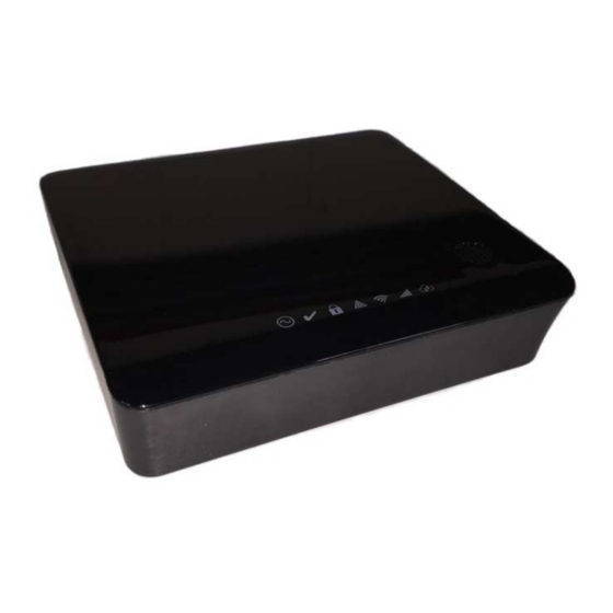
Chapter 2.0 General system operation 2.0 General system operation Your security system comprises an integrated alarm control/panel and various sensors and detectors. The system is self-contained; the control panel, integrated keypad, and standby battery are all housed within the unit. The security system has several zones of area protection. A zone is a sensor or detector that com- municates with the panel. A sensor in alarm is indicated on the integrated keypad, wireless keypad, touchscreen keypad, and by messages on the m obile phone user application. 2.1 Integrated keypad The iotega system includes a capacitive touch integrated keypad with 16 keys: numbers 0 thru 9, *, #, Fire, Auxiliary, Panic emergency keys, and shift (up arrow). During power up, the number keys illuminate in sequence several times. In normal operation, the keypad remains off when not in use. When you wave your hand in close proximity to the keypad, the number keys illuminate. Notes: The emergency keys do not illuminate unless you tap the shift key. See the Emergency Keys section for more information. You can only use the keypad for arming, disarming, and the emergency keys. The same functions are available when switching between partitions. 2.2 Panel indicators The iotega system includes seven LED status indicators: Four single-color LEDs ... - Page 7 Chapter 2.0 General system operation Item Description Power LED Ready to Arm LED Armed LED Trouble LED WiFi Signal Strength LED Cellular Signal Strength LED Remote Connection LED Power Status LED Indication Description ON (green) AC power is connected to the system. Flashing (green) System Test All status LEDs flash at the same time. There is no AC power to the system. Ready to Arm Status LED Indication Description ...
- Page 8 Chapter 2.0 General system operation Armed Status LED Indication Description ON (red) The partition is armed.. Flashing (red) The partition is in Alarm. Note: Silent a larms or panics do not flash the Alarm LED. System Test All status LEDs flash at the same time. Installer Walk Test Ready, Trouble, and Arm LEDs flash at the same time. The partition is disarmed Trouble Status LED Indication Description ON (amber) A system trouble is present. Flashing (amber) [*][2] The Trouble menu is accessed.
-
Page 9: Integrated Keypad Quick Reference
2.3 Integrated keypad quick reference Use the following table for quick reference of the integrated keypad options: Action Enter Away arm [Access Code] Stay arm [Access Code] Disarm [Access Code] Abort arming s equence [Access Code] System troubles Silence troubles [Any key] or [*][2] + [Access code View troubles [*][2] + [Access code ] + [Trouble code] For UL listed installations, you must enter your access code to silence trouble beeps and view sys- tem troubles. 2.4 Wireless LCD keypad The iotega system supports the following keypad model: WS9LCDWFx Wireless Alphanumeric LCD keypad - 8 -... -
Page 10: Wireless Keypad Symbols
ON (green) The partition is ready to arm. There are no fire or CO alarm conditions. Armed ON/flashing (red) The partition is armed.. Trouble ON (yellow) A system trouble is present. Flashing Keypad low battery Power ON (green) AC power is connected to the keypad. 2.4.2 Wireless keypad quick reference When using the wireless keypad, the iotega system uses shortcut keys to access options or features. Additionally, it uses a menu-based navigation system. Use the scroll keys t o scroll through the list of options contained within the current menu. Note: Your installer must enable and configure some features. Action Press Away Arm for 2 seconds + [Access Code Stay Arm for 2 seconds + [Access Code Disarm [Access Code] Abort arming s equence [Access Code] Bypassing - All bypass commands begin with [*][1] + [Access Code Bypass individual zones... -
Page 11: Important Notice
Chapter 2.0 General system operation 2.5 Important notice A security system cannot prevent emergencies. It is only intended to alert you and your monitoring station, if applicable, to an emergency situation. Security systems are generally very reliable, but they may not work under all conditions and they are not a substitute for prudent security practices or life and property insurance. Your security system must be installed and serviced by qualified secur- ity professionals. These professionals can instruct you on the level of protection that has been provided and on system operations. 2.5.1 Power save mode When the panel is in Power Save mode, it is saving battery life. The integrated keypad is not t urned on until there is a specific reason, such as a hand wave in front of the panel, or the start of an entry delay. When initiated, the status indicators stay on for 30 seconds before turning off. In this mode, the panel is still f unctioning, but nothing is visible. Note: For UL listed installations, the user app and touchscreen keypad functions are not available in this mode; therefore, you must use the integrated keypad or the wireless keypad to arm or disarm the system. 2.6 Language selection The s ystem supports the following three languages: English French ... -
Page 12: Arming The System
Chapter 3.0 Arming the system 3.0 Arming the system You can arm the system using the following options: Integrated keypad Wireless keypad Touchscreen keypad User app (Operation with the user app was not evaluated by UL/ULC.) Wireless key (Refer to the Using wireless keys section for a list of UL/ULC listed com- patible wireless keys.) 3.1 Stay arming Stay arming arms only the perimeter of the premises permitting movement inside. Note: To arm the system in Stay mode, your installer must enroll and configure at least one zone as an Interior Stay/Away or a Delay Stay/Away type of zone. 3.1.1 Stay arming on the integrated keypad To arm the system in Stay mode on the integrated keypad, complete the following steps: 1. Ensure all protected doors and windows are secure or bypassed and that the R eady indic- ator is on. -
Page 13: Silent Exit Delay
Chapter 3.0 Arming the system Exit Delay timer begins counting down. When the exit delay timer expires, arming the system, the following events occur: Ready i ndicator turns off.. Armed indicator remains on. Bypass or system indicator activates To cancel the arming sequence, enter your access code. 3.2 Silent exit delay If the system is armed in Stay mode or using the No-entry arming method, the keypad buzzer is silenced and the exit time is doubled for that exit period only. (SIA CP-01 only.) 3.3 No-entry arming No-entry armingarms the system in Stay or Away mode after the exit delay expires and removes the entry delay. Notes: All zones programmed as Delay function the same way as instant zones. This feature is only available on the touchscreen keypad and user app. 3.4 Away arming Away arming arms the entire system, including the perimeter and interior devices. 3.4.1 Away arming on the integrated keypad To arm the system in Away mode on the integrated keypad, complete the following steps: 1. ... -
Page 14: Quick Exit
Chapter 3.0 Arming the system 2. Enter your access code. Press and hold the Away Arm function key for 2 seconds and enter your access code, if required. If zones have been bypassed, a warning appears To cancel the arming sequence, enter your access code. Note: Your installer configures the exit delay time. 3.5 Quick exit If the system is armed and you must exit, use the Quick Exit function to avoid disarming and rearm- ing the system. Using this function gives you 2 minutes to exit the premises. When the door is closed after exiting, the remaining exit time is cancelled. Note: This feature is not available on the integrated keypad. 3.5.1 Quick exit on the wireless keypad To use the Quick Exit function o n the wireless keypad, complete the following steps: 1. When system is armed and the Armed indicator is on, press and hold the Quick Exit key for 2 seconds.. 2. Exit the premises before the exit delay timer expires. After exiting, the delay timer is can- celed. 3.6 Arming errors and exit faults Your security system audibly notifies you of any errors when you are attempting to arm the system ... -
Page 15: Alarm Cancel Window
Chapter 3.0 Arming the system 3.7 Alarm cancel window There is a period of time in which you can cancel the alarm transmission. W hen the programmed alarm transmission delay expires, canceling an alarm sends a message to the monitoring station. When the cancellation message is successfully transmitted, the system beeps six times. Note: Your installer must enable and configure this feature. For CP-01 systems, alarm transmission delay must not exceed 45 seconds. 3.8 Bypass zones Use the zone bypassing feature when you need access to a protected area while the system i s armed, or when a zone is temporarily out of service, but you need to arm the system. Bypassed zones are not able to sound an alarm. As a result, bypassing zones reduces the level of security. If you are bypassing a zone because it is not working, call a service technician immediately to resolve the problem and restore your system to proper working order. Ensure that no zones are unintentionally bypassed when arming your system. Zones cannot be bypassed once the system is armed. Bypassed zones, except for 24-hour zones, are automatically unbypassed each time the system is disarmed and must be bypassed again before the next arming, if needed. Notes: 24-hour zones can only be unbypassed manually. For UL listed installations, zones can only be bypassed manually. - 14 -... -
Page 16: Disarming The System
Chapter 4.0 Disarming the system 4.0 Disarming the system You can arm the system using the following options: Integrated keypad Touchscreen keypad Wireless keypad User app (Operation with the user app was not evaluated by UL/ULC.) Wireless key (Refer to the Using wireless keys section for a list of UL/ULC listed com- patible wireless keys.) 4.1 Disarming on the integrated keypad To disarm the system on the integrated keypad, complete the following steps: 1. Enter your access code. 2. If you open the entry/exit door, a continuous tone indicates that entry delay has started. Enter your access code within ____ seconds to avoid an alarm condition. Your installer can program this time. Note: When disarming the system during entry delay, the tone is silenced when you enter the first digit of your access code. If your access code is invalid, the tone starts again. 4.2 Disarming on the wireless keypad To disarm the system on the wireless keypad, complete the following steps: 1. ... -
Page 17: Using Wireless Keys
5.0 Using wireless keys In addition to the keypad, you can control your system with two-way wireless keys. All wireless key buttons are programmable. Your installer can verify the functions for each key. Using a two-way wireless key, you can arm or disarm the system while you are in close proximity to your house, or you can call for help. The following wireless keys are compatible with the iotega system: Note: The button functions listed are the default for each wireless key. PG4929/PG8929/PG9929 PG4939/PG8939/PG9939 PG4949/PG8949/PG9949 1. Away Arm ... -
Page 18: User Access Codes
Chapter 6.0 User access codes 6.0 User access codes The iotega system supports up to 100 users, including the Master user. By default, user #1 is the Master user. You cannot disable or delete this user from the system. The system also supports an additional two duress codes, one for each partition. From the touchscreen keypad, you can program and configure user types for users 2 through 100. You can assign a user to one or both partitions and enable or disable system interaction. User access codes are four digits and must be unique; the system does not duplicate codes. If you program a duplicate code, the system errors and rejects the code. If you try to change an existing user code to a one that is already programmed, the system errors and rejects the change. 6.1 Access code types The iotega system provides the following user access code types: Master code This is the system master code. You cannot disable or delete this code, but you can change it in the user app or on the touchscreen keypad. Use this code to pro- gram all other access codes, including the duress codes. You can use this code to do all user-level functions, except to access Installer mode. User codes There are two access levels for user codes: Level 1 - Supervisor/Administrator Level 2 - Basic/Standard User Each level has different permissions. S ee the following sections for descrip- tions of each level. -
Page 19: Level 2 Access (Basic/Standard User)
Chapter 6.0 User access codes Create new users and user labels Program duress codes Note: Users can only add, edit, or delete users that are assigned to the same partition as they are. 6.1.2 Level 2 access (basic/standard user) Users at this level have access to basic security functions but are limited based on their partition assignment. Users can do the following actions on their partitions: Arm/disarm Bypass/unbypass Chime enable/disable View system troubles View alarm memory View event history - 18 -... -
Page 20: Additional Features
Chapter 7.0 Additional features 7.0 Additional features The following sections list additional feature of your iotega system. 7.1 System lockout due to invalid attempts If configured, your system automatically locks out inputs from all keypads for a specified duration if you enter too many invalid access codes. When you tap or press any keys, an error tone sounds. Emergency keys are still active during keypad lockout. Note: Your installer must configure this feature and the lockout duration. 7.2 Burglary verification The control panel includes cross zone and sequential detection features that require a trip on two or more zones within a given time period, to generate a confirmed alarm for police response. Note: Your installer must enable and configure this feature. 7.3 Swinger shutdown The panel has a swinger shutdown feature that shuts down a zone after a programmable number of trips. All burglary zone types have this feature enabled in CP-01 installations. For SIA CP-01 classified installations, the swinger shutdown feature is programmed such that one or two trips shuts down the zone. The zone is restored after a manual reset by entering the access code at the time of disarming the alarm system, or it is reset automatically after 8 hours with no trips on any zones. Note: Your installer must be enable and configure this feature. 7.4 Fire alarm verification Fire alarm verification is an available option for fire zones. If configured, when the conditions for ... -
Page 21: Emergency Keys
Chapter 8.0 Emergency keys 8.0 Emergency keys IMPORTANT: EMERGENCY USE ONLY! The emergency keys generate a fire, auxiliary, or panic alarm and alerts the monitoring station. 8.1 Emergency keys on the integrated keypad To use the emergency keys on the integrated keypad, complete the following steps: 1. Tap the shift key (up arrow) on the keypad. T he emergency keys illuminate. Fire Auxiliary Panic 2. Touch a nd hold the Fire, Auxiliary, or Panic key for 2 seconds. The system beeps to indic- ate the alarm input was accepted and transmission is underway. The Fire key activates the siren in the pulsed fire pattern. For Auxiliary alarms, the system beeps again when the monitoring station acknowledges the signal. The Panic alarm is completely silent. 3. To return to the number keypad without using the emergency keys, tap the [#] key. 8.2 Emergency keys on the wireless keypad To use the emergency keys on the wireless keypad, press both keys of the emergency type and hold ... -
Page 22: Fire Alarm Pulsed Siren (Temporal 3)
Chapter 8.0 Emergency keys 8.3.1 Fire alarm pulsed siren (temporal 3) In the event of a fire alarm, follow your emergency evacuation plan immediately! The fire alarm t emporal/pulsed siren sounds of three short pulses followed by a 1.5-second pause, then repeats. . If the fire alarm was accidental, e.g. burnt toast, bathroom steam, etc., enter your access code to silence the alarm and call your monitoring station to avoid a dispatch. Note: Verify with your alarm company that your system is equipped with fire detection. For information on resetting smoke detectors see Resetting Smoke Detectors. 8.3.2 Carbon monoxide (CO) alarm Activation of your CO alarm indicates the presence of carbon monoxide (CO), which can be fatal. Carefully review your Carbon Monoxide Alarm Installation/User Guide to determine the necessary actions required to ensure your safety and ensure that the equipment is operating correctly. Incor- porate the steps outlined in the guide into your evacuation plan. An alarm is indicated by the following conditions: The red LED on the CO detector flashes rapidly and buzzer sounds with a repeating cadence of four quick beeps, 5-second pause, four quick beeps. The siren connected to the control panel produces the same cadence as above. The system provides audible and visual indication of the CO alarm. ... -
Page 23: Viewing Troubles
Chapter 9.0 Viewing troubles 9.0 Viewing troubles When the system detects a trouble condition, the Trouble i ndicator turns on and the system beeps every 10 seconds. T ap any key on the integrated keypad to silence the beeps. Alternatively, press the [*] key on the wireless keypad. Note: For UL listed installations, you must enter your access code to view system troubles. To view troubles on either keypad, do the following steps: 1. Enter [*][2]. 2. Enter your access code, if required. T he Trouble indicator flashes if an access code is required. The system indicates top-level trouble codes by illuminating the corresponding numbers on the keypad, and the Trouble indicator flashes once with a pause, then repeats. 3. Tap or press one of the numbers to see the next level code. A t the second level, the Trouble indicator flashes twice with a pause, then repeats. 4. Repeat step 3 to go to the next level. The system beeps if there is no third-level trouble condition. At this level, the Trouble indicator flashes three times with a pause, then repeats. If there is more than one zone in trouble, each zone number flashes in sequence until you exit the trouble menu or when the time expires. At this level, the Trouble indicator flashes three times with a pause, then repeats. 5. Tap or press [#] to return to the previous level trouble code or to exit the trouble menu. ... - Page 24 Chapter 9.0 Viewing troubles Top level Second level Third level Device type Trouble type Device ID Keypad AC (WiFi keypads only) 1 to 9 Battery trouble (wireless only) Tamper (wireless o nly) Fault (supervision) ( onboard, wireless , and WiFi keypads) Not networked (wireless o nly) Repeater 1 to 8 Battery trouble Tamper Fault (supervision) Not networked RF jam Wireless key Future use 1 to 32 Battery trouble...
-
Page 25: Using Z-Wave Devices
Chapter 10.0 Using Z-Wave Devices 10.0 Using Z-Wave Devices The Smartlink user app and web portal supports Z-Wave-enabled devices, such as lights, door locks, and switches. 10.1 Z-Wave Alliance Certification The iotega panel is a security-enabled Z-Wave Plus product that can use encrypted Z-Wave Plus messages to communicate to other Z -Wave Plus products. 10.2 Adding or Removing a Controller To add the panel as a secondary controller to another Z-Wave network, complete the following steps: 1. Put the primary c ontroller into Inclusion mode. R efer to the controller manual for more information. In the Smartlink web portal, under Home Control, click Device Control. Under Setup, click Tools, then click Add/Remove Z-Wave Controller. To remove the panel as a secondary controller and re-establish it as primary, repeat the steps, chan- ging the primary controller in step 1 to Exclusion mode. -
Page 26: Editing Or Removing A Device
10.6.1 Editing or Removing a Device To edit or remove a device, complete the following steps: 1. From the Settings screen, tap Edit Device, then select the device you want to edit or remove. Update the device name and tap Done to save your changes. Alternatively, tap Remove Device to remove it from your system. 10.7 Device Interoperability Your dealer can provide you with a list of currently supported Z-Wave devices. However, all Z- Wave Plus devices, supported and unsupported, are partially or fully operable. At a minimum, listen- ing nodes function as message repeaters. 10.8 Z-Wave Association Groups The iotega panel supports association group 1 with up to 100 nodes. A ssociation group 1 notifies associated nodes of the device status. The panel sends a Z-Wave Basic Report as a bitmap with the following property values: Property Low Battery AC Failure No Battery Tamper 10.9 Responding to the Basic Command If this device receives a Basic Get request, it responds with the Z-Wave Basic Report. Refer to the Z-Wave Association Groups section for more information. -
Page 27: Safety Instructions
Chapter 11.0 Safety instructions 11.0 Safety instructions This equipment is direct plug-in. I t must be installed and used within an environment that provides the pollution degree max 2, over voltages category II, in non-hazardous, indoor locations only. This equipment has no mains on/off switch. If you must quickly disconnect the equipment, the plug of the direct plug-in power supply is intended to serve as the disconnecting device. It is imperative that access to the mains plug and associated mains socket/outlet, is never obstructed. When using equipment connected to the mains, you must always follow b asic safety instructions. T o reduce the risk of fire, electric shock and/or injury, observe the following instructions: Use only authorized accessories with this equipment. Ensure that cables are positioned so that accidents cannot occur. Connected cables must not be subject to excessive mechanical strain. Do not spill any type of liquid on the equipment. - 26 -... -
Page 28: Locating Detectors And Escape Plan
Chapter 12.0 Locating detectors and escape plan 12.0 Locating detectors and escape plan The following information is for general guidance only and it is recommended that local fire codes and regulations be consulted when locating and installing smoke and CO alarms. 12.1 Smoke detectors Research has shown that all hostile fires in homes generate smoke to a greater or lesser extent. Experiments with typical fires in homes indicate that detectable quantities of smoke precede detect- able levels of heat in most cases. For these reasons, smoke alarms should be installed outside of each sleeping area and on each storey of the home. The following information is for general guidance only and it is recommended that local fire codes and regulations be consulted when locating and installing smoke alarms. It is recommended that additional smoke alarms beyond those required for minimum protection be installed. Additional areas that should be protected include: the basement; bedrooms, especially where smokers sleep; dining rooms; furnace and utility rooms; and any hallways not protected by the required units. On smooth ceilings, detectors may be spaced 9.1 meters (30 feet) apart as a guide. Other spacing may be required depending on ceiling height, air movement, the presence of joists, uninsulated ceilings, etc. Consult National Fire Alarm Code NFPA 72, CAN/ULC-S553-02 or other appropriate national standards for installation recommendations. Do not locate smoke detectors at the top of peaked or gabled ceilings; the dead air space in these locations may prevent the unit from detecting smoke. Avoid areas with turbulent air flow, such as near doors, fans or windows. Rapid air move- ment around the detector may prevent smoke from entering the unit. Do not locate detectors in areas of high humidity. Do not locate detectors in areas where the temperature rises above 38 ºC (100 ºF) or falls ... -
Page 29: Fire Escape Planning
Chapter 12.0 Locating detectors and escape plan Figure 3a Figure 4 12.2 Fire escape planning There is often very little time between the detection of a fire and the time it becomes deadly. It is thus very important that a family escape plan be developed and rehearsed. 1. Every family member should participate in developing the escape plan. Study the possible escape routes from each location within the house. Since many fires occur at night, special attention should be given to the escape routes from sleeping quarters. Escape from a bedroom must be possible without opening the interior door. Consider the following when making your escape plans: Make sure that all border doors and windows are easily opened. Ensure that they are not painted shut, and that their locking mechanisms operate smoothly. If opening or using the exit is too difficult for children, the elderly or handicapped, plans for rescue should be developed. This includes making sure that those who are to perform the rescue can promptly hear the fire warning signal. If the exit is above the ground level, an approved fire ladder or rope should be provided as well as training in its use. Exits on the ground level should be kept clear. Be sure to remove snow from exterior patio doors in winter; outdoor furniture or equipment should not block exits. Each person should know the predetermined assembly point where everyone can be accoun- ted for (e.g., across the street or at a neighbor's house). Once everyone is out of the build- ing, call the fire department. A good plan emphasizes quick escape. Do not investigate or attempt to fight the fire, and ... -
Page 30: Carbon Monoxide Detectors
Chapter 12.0 Locating detectors and escape plan Figure 5 12.3 Carbon monoxide detectors Carbon monoxide is colorless, odorless, tasteless, and very toxic, it also moves freely in the air. CO detectors can measure the concentration and sound a loud alarm before the CO reaches a potentially harmful level. The human body is most vulnerable to the effects of CO gas during sleeping hours; therefore, locate CO detectors in or as near as possible to sleeping areas of the home. For max- imum protection, locate a CO alarm outside primary sleeping areas or on each level of your home. Figure 5 indicates the suggested locations in the home. Do NOT place the CO alarm in the following areas: Where the temperature may drop below -10 ºC (14 ºF) or exceed 40 ºC (104 ºF) Near paint thinner fumes Within 1 .5 meters (5 feet) of open flame appliances, such as furnaces, stoves, and fire- places In exhaust streams from gas engines, vents, flues, or chimneys Do not place in close proximity to an automobile exhaust pipe; as this damages the detector. REFER TO THE CO DETECTOR INSTALLATION AND OPERATING INSTRUCTION SHEET FOR SAFETY INSTRUCTIONS AND EMERGENCY INFORMATION. - 29 -... -
Page 31: Regulatory Agency Statements
Chapter 12.0 Regulatory agency statements 12.0 Regulatory agency statements FCC MODIFICATION STATEMENT Digital Security Controls has not approved any changes or modifications to this device by the user. Any changes or modifications could void the user’s authority to oper- ate the equipment .Digital Security Controls n’approuve aucune modification apportée à l’appareil par l’utilisateur, quelle qu’en soit la nature. Tout changement ou modification peuvent annuler le droit d’utilisation de l’appareil par l’utilisateur. FCC AND ISED CANADA INTERFERENCE STATEMENT This device complies with Part 15 of the FCC Rules and ISED Canada licence-exempt RSS standard(s). Operation is subject to the following two conditions: (1) this device may not cause interference, and (2) this device must accept any interference, including interference that may cause undesired operation of the device. Le présent appareil est conforme aux CNR d'ISED Canada applicables aux appareils radio exempts de licence. L'exploitation est autorisée aux deux conditions suivantes : (1) l'appareil ne doit pas produire de brouillage, et (2) l'utilisateur de l'appareil doit accepter tout brouillage radioélectrique subi, ê me si le brouillage est susceptible d'en compromettre le fonctionnement. FCC CLASS B DIGITAL DEVICE NOTICE This equipment has been tested and found to comply with the limits for a Class B digital device, pursuant to part 15 of the FCC Rules. These limits are designed to provide reasonable protection against harmful interference in a residential installation. This equipment generates uses and can radiate radio frequency energy and, if not installed and used in accordance with the instructions, may cause harmful interference to radio communications. However, there is no guarantee that interference will not occur in a particular installation. If this equipment does cause harmful interference to radio or television reception, which can be determined by turning the equipment off and on, the user is encouraged to try to correct the interference by one or more of the following measures: - Reorient the receiving antenna. - Increase the separation between the equipment and receiver. - Connect the equipment into an outlet on a circuit different from that to which the receiver is connected. - Consult the dealer or experienced radio/television technician for help. CAN ICES-3 (B) / NMB-3 (B) The reference to the WS900-xx throughout this manual is applicable to the following model numbers: WS900-19 and WS900-29. FCC ID:F5316WS90019 FCC ID:F5316WS900-29 IC: 160A-WS90019 ... - Page 32 Chapter 12.0 Regulatory agency statements PRIVACY STATEMENT The Tyco cloud collects the following Data from the iotega panel (public IP a ddress, security events and statuses, security configuration, and system diagnostics) in order to [improve system performance, troubleshoot customer issues, and improve user experience ]. Y ou have the right to access, correct and request removal of your personal data by contacting info@tycosecurityproducts.com and the right to lodge a complaint with a supervisory authority. T yco will not transfer this data to other parties, except for our cloud service provider in the US, with whom we have contractual Personal Data Processing Terms and EU Standard Contractual Clauses. T yco uses industry-standard safeguards to protect your personal information. F ind out more in our Privacy Statement at www.tyco.com/privacy. Y our personal information will be retained as long as necessary to achieve the purpose for which it was collected and for any period thereafter as legally required or permitted by applicable law. SIMPLIFIED DECLARATION OF CONFORMITY Hereby, Tyco Safety Products Canada Ltd declares that the radio equipment type Wireless Alarm System with Integral Cellular Alarm Communicator is in compliance with Directive 2014/53/EU. The following models are covered by this guide: WS900-14, WS900-24, 3G7090, LT7090 (used in North America only), WS901-14, WS901-24EU, WS901-18, WS901-28 and 3G7090-EU. The full text of the EU declarations of conformity for the models mentioned below are available at the following internet addresses: Model WS901-14: http://dsc.com/pdf/1707001 Model WS901-24EU: http://dsc.com/pdf/1707002 Model WS901-18: http://dsc.com/pdf/1707003 Model: WS901-28: http://dsc.com/pdf/1707004 Model: 3G7090-EU: http://dsc.com/pdf/1707009 Product specifications Frequency Maximum power g1 ...
-
Page 33: Reference Sheets
Chapter 13.0 Reference sheets 13.0 Reference sheets Fill out the following information for future reference and store this guide in a safe place. 13.1 System information Mark if buttons are enabled [F] FIRE [ A] AUXILIARY [ P] PANIC The exit delay time is _______ seconds. The entry delay time is _______ s econds. 13.2 Service contact information Monitoring station information Account #: ___________________ T elephone #: __________________ Installer information: Company: ___________________ ... - Page 34 © 2017 Tyco Security Products. All Rights Reserved. • w ww.dsc.com The trademarks, logos, and service marks displayed on this document are registered in the United States and/or other countries. A ny misuse of the trademarks is strictly prohibited and Tyco Security Products will aggressively enforce its intellectual property rights to the fullest extent of the law, including pursuit of criminal prosecution ...
Need help?
Do you have a question about the iOtega and is the answer not in the manual?
Questions and answers