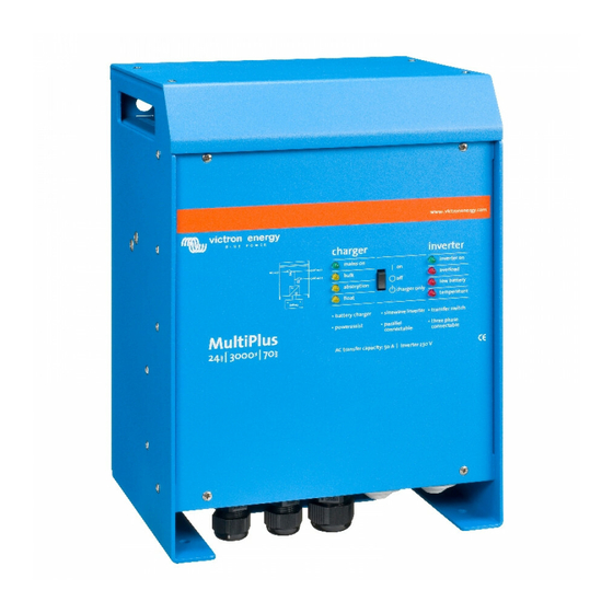
Victron energy Phoenix MultiPlus 24/3000/70 User Manual
Con ve.bus
Hide thumbs
Also See for Phoenix MultiPlus 24/3000/70:
- Installation manual (107 pages) ,
- User manual (44 pages) ,
- Manual (39 pages)

Subscribe to Our Youtube Channel
Related Manuals for Victron energy Phoenix MultiPlus 24/3000/70


Summary of Contents for Victron energy Phoenix MultiPlus 24/3000/70
- Page 1 MANUAL Phoenix MultiPlus Con VE.Bus 12/3000/120 24/3000/70 48/3000/35 Remark: DIP switch functionality has changed. Parallel and 3-phase systems can be now configured with DIP switches.
- Page 3 EXCEED THE PURCHASE PRICE OF THE VICTRON ENERGY PRODUCTS DESCRIBED HERE IN. Victron Energy B.V. reserves the right to revise and improve its products as it sees fit. This publication describes the state of this product at the time of its publication and...
-
Page 6: Safety Instructions
1. SAFETY INSTRUCTIONS In general Please read the documentation supplied with this product first, so that you are familiar with the safety signs en directions before using the product. This product is designed and tested in accordance with international standards. The equipment should be used for the designated application only. -
Page 7: Transport And Storage
Install the product in a heatproof environment. Ensure therefore that there are no chemicals, plastic parts, curtains or other textiles, etc. in the immediate vicinity of the equipment. Transport and storage On storage or transport of the product, ensure that the mains supply and battery leads are disconnected. - Page 8 2. DESCRIPTION 2.1 In general The basis of the MultiPlus is an extremely powerful sine inverter, battery charger and automatic switch in a compact casing. The MultiPlus features the following additional, often unique characteristics: Automatic and uninterruptible switching In the event of a supply failure or when the generating set is switched off, the MultiPlus will switch over to inverter operation and take over the supply of the connected devices.
- Page 9 Autonomous operation when the grid fails Houses or buildings with solar panels or a combined micro-scale heating and power plant or other sustainable energy sources have a potential autonomous energy supply which can be used for powering essential equipment (central heating pumps, refrigerators, deep freeze units, Internet connections, etc.) during a power failure.
- Page 10 Learn more about batteries and battery charging To learn more about batteries and charging batteries, please refer to our book ‘Energy Unlimited’ (available free of charge from Victron Energy and downloadable from www.victronenergy.com). For more information about adaptive charging please look...
- Page 11 3 OPERATION 3.1 On/Off/Charger Only Switch When switched to "on", the product is fully functional. The inverter will come into operation and the LED "inverter on" will light up. An AC voltage connected to the "AC in" terminal will be switched through to the "AC out"...
- Page 12 3.3.3 Activating equalisation or forced absorption The MultiPlus can be put into both these states from the remote panel as well as with the front panel switch, provided that all switches (front, remote and panel) are set to “on” and no switches are set to “charger only”. In order to put the MultiPlus in this state, the procedure below should be followed.
-
Page 13: Led Indications
3.4 LED Indications LED off LED flashes LED illuminated Inverter Charger inverter mains on inverter on Bulk overload The inverter is on and supplies power to the load. Absorption low battery charger only Float temperature Charger inverter mains on inverter on The nominal output of the Bulk overload... - Page 14 Charger inverter mains on inverter on Bulk overload The battery is almost fully exhausted. absorption low battery charger only Float temperature Charger inverter mains on inverter on Bulk overload The inverter has switched off due to low battery voltage. absorption low battery charger only...
- Page 15 Charger inverter -If the LEDs are flashing mains on inverter on alternately, the battery is nearly exhausted and the nominal Bulk overload output is exceeded. -If "overload" and "low battery" flash simultaneously, the ripple absorption low battery voltage on the battery terminals charger is too high.
- Page 16 Charger inverter mains on inverter on The mains voltage is switched Bulk overload through and the charger operates in absorption mode. absorption low battery charger only Float temperature Charger inverter mains on inverter on The mains voltage is switched Bulk overload through and the charger operates in float mode.
- Page 17 Special Indications PowerControl charger inverter mains on inverter on The AC input is switched through. The AC output current bulk overload is equal to the preset maximum input current. The absorption low battery charge current is reduced to 0. charger only float temperature...
- Page 18 4. Installation This product may only be installed by a qualified electrical engineer. 4.1 Contents of the box Phoenix MultiPlus. • Manual. • Suspension bracket • Temperature sensor • Warning sticker for battery charging • Four fixing screws • Fuse •...
- Page 19 4.3 Requirements Philips screwdriver (PH2) for removing the front. • Flat screwdriver (0.6x3.5) for connecting the AC leads. • Isolated box spanner (13 mm) for securing the terminal nuts and the fuse. • Two battery cables including battery terminals and cable ends. •...
- Page 20 4.5 Connection of the AC cabling This is a Safety Class I product (supplied with a protective grounding terminal). Uninterruptible protective grounding must be provided at the AC input and/or output terminals and/or chassis grounding point located externally on the product. See the following instructions: The MultiPlus: the output neutral wire will automatically be bonded to the chassis (with the output ground relay, see appendix) when no external AC source is available (backfeed / safety relay open and product...
-
Page 21: Parallel Connection
4.6.2 Voltage Sense Two sense wires may be connected to compensate possible battery cable losses during charging. Use wires of at least 0.75mm . For connection see Appendix 0. 4.6.3 Temperature Sensor The temperature sensor supplied with the product may be used for temperature- compensated charging (see Appendix 0). - Page 22 Temperature compensation during battery charging responds to the sensor indicating the highest temperature. Voltage sensing must be connected to the master (see Section 5.5.1.4). • If more than three units are connected in parallel in one system, a dongle is required (see •...
- Page 23 5. Configuration Settings may only be changed by a qualified electrical engineer. • Read the instructions thoroughly before implementing changes. • During setting of the charger, the AC input must be removed. • 5.1 Standard settings: ready for use On delivery, the MultiPlus is set to standard factory values. In general, these settings are suitable for single-unit operation.
- Page 24 VirtualSwitch controls the multi-functional relay PowerAssist 5.2 Explanation of settings Settings that are not self-explanatory are described briefly below. For further information, please refer to the help files in the software configuration programs (see Section 5.3). Inverter frequency Output frequency if no AC is present at the input. Adjustability: 50Hz;...
- Page 25 Ground relay (see appendix B) With this relay (H), the neutral conductor of the AC output is grounded to the chassis when the back feed safety relay is open. This ensures the correct operation of earth leakage circuit breakers in the output. If a non-grounded output is required during inverter operation, this function must be turned off.
- Page 26 Not adjustable with DIP switches. BoostFactor Change this setting only after consulting with Victron Energy or with an engineer trained by Victron Energy! Not adjustable with DIP switches.
- Page 27 Multi-functional relay By default, the multi-functional relay is set as an alarm relay, i.e. the relay will de- energise in the event of an alarm or a pre-alarm (inverter almost too hot, ripple on the input almost too high, battery voltage almost too low). Not adjustable with DIP switches.
- Page 28 A RJ45 UTP cable and the MK2.2b RS485-to-RS232 interface. If your computer has no RS232 connection, but does have USB, you will also need a RS232-to-USB interface cable. Both are available from Victron Energy. 5.3.1 VE.Bus Quick Configure Setup VE.Bus Quick Configure Setup is a software program with which systems with a maximum of three Multi’s (parallel or three phase operation) can be configured in a...
- Page 29 5.5 Configuration with DIP switches A number of settings can be changed using DIP switches (see appendix A, position This is done as follows: Turn the Multi on, preferably unloaded en without AC voltage on the inputs. The Multi will then operate in inverter mode. Step 1: Setting the DIP switches for: - the required current limitation of the AC input.
- Page 30 Procedure The AC input current limit can be set using DIP switches ds8, ds7 and ds6 (default setting: 30A, automatically limited to 16A in 16A models). Procedure: set the DIP switches to the required value: ds8 ds7 ds6 off = 4A (0,9kVA at 230V) on = 6A (1,4kVA at 230V) off = 10A (2.3kVA at 230V) on = 12A (2.8kVA at 230V)
- Page 31 5.5.1.4 Stand-alone, parallel and 3-phase operation Using DIP switches ds2 and ds1, three system configurations can be selected. NOTE: When configuring a parallel or 3-phase system, all related devices should • be interconnected using RJ45 UTP cables (see appendix C, D). All devices must be turned on.
- Page 32 DIP switches ds2 and ds1 are reserved for the selection of stand-alone, parallel 3-phase operation Stand-alone operation Step 1: Setting ds2 and ds1 for stand-alone operation DS-8 AC input Set as desired DS-7 AC input Set as desired DS-6 AC input Set as desired DS-5 AES Set as desired...
- Page 33 Parallel operation (appendix C) Step 1: Setting ds2 and ds1 for parallel operation Master Slave 1 Slave 2 (optional) DS-8 AC input DS-8 na DS-8 na DS-7 AC input DS-7 na DS-7 na DS-6 AC input DS-6 na DS-6 na DS-5 AES DS-5 na DS-5 na...
- Page 34 We recommend making a note of the settings, and filing this information in a safe place. You can now re-use the DIP switches to apply the remaining settings (step 2).
- Page 35 Three phase operation (appendix D) Step 1: Setting ds2 and ds1 for 3-phase operation Leader (L1) Follower (L2) Follower (L3) DS-8 AC input DS-8 Set DS-8 Set DS-7 AC input DS-7 Set DS-7 Set DS-6 AC input DS-6 Set DS-6 Set DS-5 AES DS-5 na DS-5 na...
- Page 36 We recommend making a note of the settings, and filing this information in a safe place. You can now re-use the DIP switches to apply the remaining settings (step 2).
- Page 37 5.5.2 Step 2: Other settings The remaining settings are not relevant (na) for slaves. Some of the remaining settings are not relevant for followers (L2, L3). These settings are imposed on the whole system by the leader L1. If a setting is irrelevant for L2, L3 devices, this is mentioned explicitly.
- Page 38 Step 2: Exemplary settings for stand-alone mode Example 1 is the factory setting (since factory settings are entered by computer, all DIP switches of a new product are set to ‘off’). DS-8 Ch. voltage DS-8 DS-8 DS-8 DS-7 Ch. voltage DS-7 DS-7 DS-7...
- Page 39 Step 2: Exemplary setting for parallel mode In this example, the master is configured according to factory settings. The slaves do not require setting! Master Slave 1 Slave 2 DS-8 Ch. voltage(GEL 14,4V) DS-8 na DS-8 na DS-7 Ch. voltage(GEL 14,4V) DS-7 na DS-7 na DS-6 Absorption time (8 h)
- Page 40 To start the system: first, turn all devices off. The system will start up as soon as all devices have been turned on.
- Page 41 Avoid moisture and oil/soot/vapours, and keep the device clean. 7 Error indications With the procedures below, most errors can be quickly identified. If an error cannot be resolved, please refer to your Victron Energy supplier. 7.1 General error indications Problem Cause...
- Page 42 “Low battery” and The inverter is switched off due Install batteries with a larger “overload” LEDs light. to an excessively high ripple capacity. Fit shorter and/or voltage on the input. thicker battery cables, and reset the inverter (switch off, and then on again).
- Page 43 One alarm LED The inverter is switched off due to Check this table for appropriate lights and the alarm activation by the lighted LED. measures in regard to this alarm second flashes. The flashing LED indicates that the state. inverter was about to switch off due to the related alarm.
- Page 44 7.2 Special LED indications (for the normal LED indications, see section 3.4) Bulk and absorption LEDs flash synchronously Voltage sense error. The voltage (simultaneously). measured at the voltage sense connection deviates too much (more than 7V) from the voltage on the positive and negative connection of the device.
- Page 45 7.3 VE.Bus LED indications Equipment included in a VE.Bus system (a parallel or 3-phase arrangement) can provide so-called VE.Bus LED indications. These LED indications can be subdivided into two groups: OK codes and error codes. 7.3.1 VE.Bus OK codes If the internal status of a device is in order but the device cannot yet be started because one or more other devices in the system indicate an error status, the devices that are in order will indicate an OK code.
- Page 46 7.3.2 VE.Bus error codes A VE.Bus system can display various error codes. These codes are displayed with the "inverter on", "bulk", "absorption" and "float" LEDs. To interpret a VE.Bus error code correctly, the following procedure should be followed: Is the "inverter on" LED flashing? If not, then there is no VE.Bus error code. If one or more of the LEDs "bulk", "absorption"...
- Page 47 3) Switch on all other devices one by one until the error message reoccurs. 4) Update the firmware in the last device that was switched on. Internal error. Should not occur. Switch all equipment off, and then on again. Contact Victron Energy if the problem persists.
-
Page 48: Technical Specifications
8. Technical specifications 48/3000/ MultiPlus 12/3000/120 24/3000/70 PowerControl / PowerAssist Input voltage range: 187-265 VAC Input frequency: 45 – 55 AC inputs Maximum feed through current (A) 16 or 30 16 or 30 16 or 30 INVERTER Input voltage range (V DC) 9,5 –... - Page 49 1) Can be adjusted to 60Hz; 120V 60Hz on request 2) Protection a. Output short circuit b. Overload c. Battery voltage too high d. Battery voltage too low f. 230VAC on inverter output g. Input voltage ripple too high 3) Non linear load, crest factor 3:1 4) At 25 °...
- Page 50 1. VEILIGHEIDSVOORSCHRIFTEN Algemeen Lees eerst de bij dit product geleverde documentatie, zodat u bekend bent met de veiligheidsaanduidingen en aanwijzingen voordat u het product in gebruik neemt. Dit product is ontworpen en getest in overeenstemming met internationale normen. De apparatuur dient uitsluitend voor de bestemde toepassing te worden gebruikt. WAARSCHUWING: KANS OP ELEKTRISCHE SCHOKKEN.
- Page 51 Controleer voordat u het apparaat inschakelt dat de beschikbare spanningsbron overeenkomt met de configuratie-instellingen van het product zoals beschreven in de handleiding. Zorg ervoor dat de apparatuur onder de juiste bedrijfsomstandigheden wordt gebruikt. Stel het product nooit in bedrijf in een natte of in een stoffige omgeving. Zorg ervoor dat er altijd voldoende vrije ruimte (minstens 10cm) rondom het product is voor ventilatie en dat de ventilatieopeningen niet zijn geblokkeerd.
- Page 52 2. BESCHRIJVING 2.1 Algemeen De basis van de MultiPlus is een zeer krachtige sinusomvormer, acculader en omschakelautomaat in een compacte behuizing. Daarnaast heeft de MultiPlus een groot aantal vaak unieke mogelijkheden: Automatisch en onderbrekingsvrij omschakelen In geval van een netspanningstoring of wanneer het aggregaat wordt uitgeschakeld zal de MultiPlus overschakelen op omvormer bedrijf en de voeding van de aangesloten apparaten overnemen.
- Page 53 PowerAssist – Doe meer met Uw aggregaat en walstroom: de “meehelp” functie van de MultiPlus De MultiPlus werkt parallel met het aggregaat of de walaansluiting. Een tekort aan stroom wordt automatisch opgevangen: de MultiPlus haalt extra vermogen uit de accu en helpt mee.
- Page 54 2.2 Acculader Adaptieve 4-traps laadkarakteristiek: bulk – absorption – float – opslag Het microprocessor gestuurde ‘adaptieve’ accu management systeem kan afgeregeld worden voor verschillende soorten accu’s. De adaptieve functie past het laadproces automatisch aan aan het gebruik van de accu. De juiste hoeveelheid lading: aangepaste absorptie tijd Bij geringe ontlading van de accu wordt de absorptie kort gehouden om overlading en overmatig gassen te voorkomen.
- Page 55 Meer over accu’s en acculaden In ons boek ‘Altijd Stroom’ kunt U meer lezen over accu’s en het laden van accu’s (gratis verkrijgbaar bij Victron Energy en beschikbaar op www.victronenergy.com Voor meer informatie over de adaptieve laadkarakteristiek verwijzen wij U naar...
- Page 56 3.Bediening 3.1 On/Off/charger Only schakelaar Wanneer de schakelaar op “on” wordt geschakeld werkt het apparaat volledig. De omvormer zal aanschakelen en de LED “inverter on” zal gaan branden. Als er op de “AC-in” aansluiting spanning wordt aangesloten zal deze na controle en goedkeur worden doorgeschakeld naar de “AC-out”...
- Page 57 3.3.2 Forced absorption In sommige omstandigheden kan het wenselijk zijn om de accu voor een vaste tijd met een Absorption spanning te laden. In de Forced Absorption modus gaat de Phoenix Multi gedurende de ingestelde maximale absorption tijd met de normale Absorption spanning laden.
- Page 58 3.4 LED aanduidingen en hun betekenis LED uit LED knippert LED brandt Omvormer charger inverter mains on inverter on De omvormer staat aan en bulk overload levert vermogen aan de belasting. absorption low battery charger float temperature only charger inverter mains on inverter on Het nominale vermogen van de...
- Page 59 charger inverter mains on inverter on bulk overload De accu is bijna leeg. absorption low battery charger float temperature only charger inverter mains on inverter on De omvormer is uitgeschakeld bulk overload vanwege te lage accu spanning. absorption low battery charger float temperature...
- Page 60 charger inverter -Knipperen de LED’s om en om dan is de accu bijna leeg en mains on inverter on wordt het nominale vermogen bulk overload overschreden. -Als “overload” en “low battery” absorption low battery tegelijk knipperen is er een te charger hoge rimpelspanning op de float...
- Page 61 charger inverter mains on inverter on De netspanning is bulk overload doorgeschakeld en de lader laadt in de absorption fase. absorption low battery charger float temperature only charger inverter mains on inverter on De netspanning is bulk overload doorgeschakeld en de lader laadt in de float fase.
- Page 62 Speciale aanduidingen Ingesteld met begrensde ingangsstroom charger inverter De netspanning is mains on inverter on doorgeschakeld. De AC- bulk overload ingangsstroom is gelijk aan de belastingsstroom. De lader is absorption low battery teruggeregeld naar 0 A. charger float temperature only Ingesteld om bij te leveren charger inverter...
- Page 63 4. Installatie 1.1 Inhoud van de doos De doos van de MultiPlus bevat de volgende zaken: MultiPlus omvormer/acculader • Gebruikershandleiding. • Installatiehandleiding. • Zakje met aansluitmateriaal met daarin: • Temperatuursensor. • Zekering. (Mega fuse) • Vier moeren M8. • Vier sluitringen M8. •...
- Page 64 4.3 Benodigdheden Een kruiskop schroevendraaier (PH 2) voor het verwijderen van het front. • Een platte schroevendraaier (0,6x3,5) voor het aansluiten van de AC kabels. • Een geïsoleerde pijpsleutel (13 mm) voor het vastdraaien van de aansluitbouten • en de zekering. Twee accukabels (maximum lengte 6 meter) inclusief accuklemmen en •...
- Page 65 4.5 Aansluiten AC kabels Dit is een product uit veiligheidsklasse I. (dat wordt geleverd met een aardklem ter beveiliging) De in - en/ of uitgangsklemmen en/of het aard punt aan de buitenkant van het product moeten zijn voorzien van een ononderbreekbare aarding ter beveiliging.
- Page 66 4.6 Aansluitopties Naast de standaardaansluitingen kunnen er nog een aantal opties worden aangesloten. 4.6.1 Startaccu De Multi heeft een aansluiting voor het laden van een startaccu. Zie voor het aansluiten appendix 0. 4.6.2 Voltage sense Voor het compenseren van eventuele kabel verliezen tijdens het laden kunnen er twee sense draden worden aangesloten.
- Page 67 4.6.6 Parallel schakelen (zie appendix C) De MultiPlus is parallel te schakelen met meerdere identieke apparaten. Hiertoe wordt een verbinding tussen de apparaten gemaakt met behulp van standaard UTP CAT-5 kabels (UTP Patch leads). Het systeem (apparaten samen met eventueel een bedieningspaneel) dient hierna geconfigureerd te worden (zie hoofdstuk 5).
- Page 68 5. Instellingen Het wijzigen van de instellingen mag alleen worden uitgevoerd door • een gekwalificeerde elektrotechnicus. Lees voor het wijzigen goed de instructies. • Tijdens het instellen van de lader moet er geen AC ingangsspanning • aangeboden worden. 5.1 Standaard instellingen: klaar voor gebruik De MultiPlus wordt geleverd met standaard instellingen.
- Page 69 5.2 Verklaring instellingen Hieronder volgt een korte verklaring van de instellingen voor zover die niet vanzelfsprekend zijn. Meer informatie is te vinden in de help files van de software configuratie programma’s (zie paragraaf 5.3). Omvormer frequentie Uitgangsfrequentie wanneer er geen AC op de ingang aanwezig is. Instelbaar: 50Hz;...
- Page 70 Ground relay (zie appendix B) Met dit relais (H) wordt de nul geleider van de AC uitgang aan de kast geaard wanneer de teruglever veiligheidsrelais in de AC ingangen open is. Dit om de correcte werking van aardlek schakelaars in de uitgang te verzekeren. Indien een niet geaarde uitgang gewenst is tijdens omvormer bedrijf, moet deze functie uit gezet worden.
- Page 71 AC in stroomgrens Dit is de stroomgrens instelling waarbij PowerControl en PowerAssist in werking treden. De standaard instelling is 30A. Bij modellen met maximaal 16A doorschakelstroom wordt de AC in stroomgrens automatisch begrend op de maximaal toegestane waarde (16A). Zie hoofdstuk 2, het boek ‘Altijd Stroom’, of de vele beschrijvingen van deze unieke functie op onze web site www.victronenergy.com.
- Page 72 Niet instelbaar met DIP switches. BoostFactor Deze instelling alleen wijzigen na overleg met Victron Energy of een door Victron Energy getrainde installateur! Niet instelbaar met DIP switches. Multifunctioneel relais Het multifunctionele relais is standaard ingesteld als alarm relais, d.w.z.
- Page 73 RS232 aansluiting heeft, maar wel USB, heeft u ook een RS232 naar USB interface kabel nodig. Beide zijn verkrijgbaar bij Victron Energy. 5.3.1 VE.Bus Quick Configure Setup VE.Bus Quick Configure Setup is een software programma waarmee systemen met maximaal 3 Multi’s (parallel of drie fase bedrijf) op eenvoudige wijze geconfigureerd...
- Page 74 5.5 Instellen met DIP switches Introductie Een aantal instellingen kan gewijzigd worden door middel van DIP switches (zie appendix A, positie M). Dit gaat als volgt: Schakel de MultiPlus aan, bij voorkeur zonder belasting en zonder wisselspanning op de ingangen. De MultiPlus werkt dan in omvormer bedrijf. Stap 1: instellen van de DIP switches voor - De gewenste stroom begrenzing van de AC ingangen.
- Page 75 5.5.1 Stap 1 5.5.1.1 Stroom begrenzing AC ingang (standaard: 16A voor modellen met max.16A doorschakelstroom en 30A voor modellen met max. 30A doorschaklestroom) Als de gevraagde stroom (belasting + acculader van de MultiPlus) groter dreigt te worden dan de ingestelde stroom, zal de MultiPlus eerst de laadstroom verminderen (PowerControl), en vervolgens vermogen bijleveren uit de accu (PowerAssist).
- Page 76 5.5.1.3 Laadstroom begrenzing (standaard instelling 75%) Accu’s hebben de langste levensduur waanneer geladen wordt met een stroom van 10% tot 20% van de capaciteit in Ah. Voorbeeld: optimale laadstroom van een accubank 24V/500Ah: 50A tot 100A. De meegeleverde temperatuur sensor zorgt voor automatische aanpassing van de laadspanning aan de temperatuur van de accu.
- Page 77 5.5.1.4 Stand alone / parallel bedrijf / 3-fase bedrijf Met DIP switches ds2 en ds1 kunnen drie systeem configuraties gekozen worden LET OP: Tijdens het configureren van een parallel of 3-fase systeem moeten alle • betreffende apparaten aan elkaar gekoppeld zijn met UTP CAT-5 bekabeling (zie appendix C, D).
- Page 78 Voor de keuze stand alone / parallel bedrijf / 3 fase bedrijf zijn de DIP switches ds2 en ds1 gereserveerd Stand alone bedrijf Stap 1, instelling ds2 en ds1 voor stand alone bedrijf: DS-8 AC-in-1 Instellen als gewenst DS-7 AC-in-1 Instellen als gewenst DS-6 AC-in-1 Instellen als gewenst...
- Page 79 Parallel bedrijf (appendix C) Stap 1, instelling ds2 en ds1 voor parallel bedrijf: Master Slave 1 Slave 2 (optioneel) DS-8 AC-in-1 Inst. als gewenst DS-8 Niet rel. DS-8 Niet rel. DS-7 AC-in-1 Inst. als gewenst DS-7 Niet rel. DS-7 Niet rel. DS-6 AC-in-1 Inst.
- Page 80 Drie fase bedrijf (appendix D) Stap 1: instelling ds2 en ds1 voor 3-fase bedrijf: Leader (L1) Follower (L2) Follower (L3) DS-8 AC in Inst. als gew. DS-8 Inst. als gew. DS-8 Inst. als gew. DS-7 AC in Inst. als gew. DS-7 Inst.
- Page 81 5.5.2 Stap 2: overige instellingen De overige instellingen zijn niet relevant voor Slaves. Sommige van de overige instellingen zijn niet relevant voor Followers (L2, L3). Deze instellingen worden door de Leader L1 voor het hele systeem opgelegd. Als een instelling niet relevant is voor L2, L3 apparaten staat dit expliciet vermeld. ds8-ds7: instelling laadspanningen (niet relevant voor L2, L3) Absorptie Float...
- Page 82 Stap 2: voorbeeld instellingen voor stand alone bedrijf: Voorbeeld 1 is de fabrieksinstelling (de DIP switches van een nieuw product staan allemaal in de ‘off’ stand omdat de fabrieksinstelling per computer is ingevoerd). DS-8 Laadspanning DS-8 DS-8 DS-8 DS-7 Laadspanning DS-7 DS-7 DS-7...
- Page 83 Voorkom vocht en olie/roet/dampen en houd het apparaat schoon. 7 Foutindicaties Met behulp van onderstaande stappen kunnen de meest voorkomende storingen snel worden opgespoord. Indien de fout niet opgelost kan worden, raadpleeg uw Victron Energy distributeur. 7.1 Algemene fout indicaties Probleem Oorzaak Oplossing...
- Page 84 Probleem Oorzaak Oplossing Een alarm LED De omvormer is uitgeschakeld als Controleer deze tabel om brandt en de tweede gevolg van de alarmering van de acties te nemen knippert brandende LED. De knipperende overeenkomstig het alarm. LED geeft aan dat de omvormer bijna uitgeschakeld is als gevolg van het betreffende alarm.
- Page 85 De laadstroom zakt De accu is oververhit (>50° C) - Plaats de accu in een koelere terug naar 0 zodra de ruimte absorptie fase ingaat - Verlaag de laadstroom - Kijk of een van de accucellen een interne sluiting heeft De accu temperatuur sensor is stuk Maak het stekkertje van de temperatuur sensor in de Multi...
- Page 86 7.3 VE.Bus LED indicaties Apparaten die in een VE.Bus systeem zijn opgenomen (een parallel of een 3-fase opstelling) kunnen zogenaamde VE.Bus LED indicaties geven. Deze LED indicaties zijn onder te verdelen in 2 groepen: OK codes en Error codes. 7.3.1 VE.Bus OK codes Als de interne status van een apparaat in orde is maar er kan nog niet gestart worden omdat één of meer andere apparaten in het systeem een fout geven dan geven de apparaten die in orde zijn een OK code.
- Page 87 7.3.2 VE.Bus Error Codes Een VE.Bus systeem kan verschillende error codes weergeven. Deze codes worden weergegeven met de Inverter on, Bulk, Absorption en Float LED’s. Om een VE.Bus Error Code correct te interpreteren moeten de volgende stappen doorgenomen worden: Knippert de Inverter on LED? Zo nee dan is het geen VE.Bus Error Code. Indien één of meer van de LED’s: Bulk, Absorption, Float knippert dan MOET dit knipperen in tegenfase zijn met het knipperen van de Inverter on LED.
- Page 88 Bulk LED uit Absorption LED knippert knippert Bulk LED knippert Absorption LED knippert knippert Bulk LED aan Absorption LED knippert knippert...
- Page 89 4) Zorg dat de firmware in het laatst aangeschakelde apparaat ge-update wordt. Interne fout. Behoort niet voor te komen. Zet alle apparaten uit en opnieuw aan. Neem contact op met Victron Energy indien het probleem zich blijft voordoen.
- Page 90 8. Technische Specificaties MultiPlus 12/3000/120 24/3000/70 48/3000/35 PowerControl / PowerAssist Maximale doorschakelstroom (A) OMVORMER Ingangsspanningsbereik (V DC) 9,5 – 17 19 – 33 38 – 66 Uitgang (1) Uitgangsspanning: 230 VAC ± 2% Frequentie: 50 Hz ± 0,1% Continu vermogen bij 25° C (VA) (3) 3000 3000 3000...
- Page 91 1) Iedere MultiPlus kan worden ingesteld op 60Hz 2) Beveiligingen a. Kortsluiting b. Overbelasting c. Accuspanning te hoog d. Accuspanning te laag e. Accu-ompooldetectie f. Wisselspanning op de uitgang g. Ingangsspanning met een te hoge rimpel h. Temperatuur te hoog 3) Niet lineaire belasting, crest faktor 3:1 4) Bij 25°...
- Page 92 APPENDIX A Overview connections...
- Page 93 A Shore supply. AC in: (left to right) PE (ground), N (neutral), L (phase). B 2x RJ45 connector for remote control and/or parallel / three-phase operation C Load connection. AC out: (left to right) PE (ground), N (neutral), L (phase). D Megafuse F4.
- Page 94 APPENDIX B: Block diagram...
- Page 95 APPENDIX C: Parallelconnection...
- Page 96 APPENDIX D: Three phase connection...
- Page 97 APPENDIX E: Charge characteristic C h a rg e c u rre n t 1 2 0 % 1 0 0 % 8 0 % A m p s 6 0 % 4 0 % 2 0 % T i m e V o l ts C h a rg e v o lta g e T i m e...
- Page 98 APPENDIX F: Temperature compensation 15.0 14.5 14.0 13.5 13.0 Volts Volts 12.5 12.0 11.5 11.0 10.5 10.0 10 15 20 25 30 35 40 45 50 55 60 Battery temperature Default output voltages for Float and Absorption are at 25° C. Reduced Float voltage follows Float voltage and Raised Absorption voltage follows Absorption voltage.
- Page 99 APPENDIX G: Dimensions...
- Page 101 Serial number: Distributor: Victron Energy B.V. Phone:+31 (0)36 535 97 00 The Netherlands Fax: +31 (0)36 535 97 40 E-mail:sales@victronenergy.com Web site: http://www.victronenergy.com Article number: PMP012302000 Version: Date: 30-10-2007...
Need help?
Do you have a question about the Phoenix MultiPlus 24/3000/70 and is the answer not in the manual?
Questions and answers