
Subscribe to Our Youtube Channel
Related Manuals for Teeter Fit Series


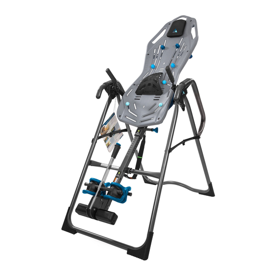
Summary of Contents for Teeter Fit Series
- Page 1 Fit Series Assembly Instructions Inversion Tables YEAR * Inversion Table images may vary slightly from your model. The Fit-100 is shown here.
- Page 2 BEFORE YOU BEGIN: Review all steps before beginning assembly and read all precautions before using the inversion table. Carefully adhere to the Assembly Instructions and Owner’s Manual to help ensure safety and product integrity. IMPORTANT SAFETY INSTRUCTIONS READ ALL INSTRUCTIONS BEFORE USING THE INVERSION TABLE. WARNING WARNING - To reduce the risk of injury to persons: •...
- Page 3 BEFORE YOU BEGIN: Review all steps before beginning assembly and read all precautions before using the inversion table. Carefully adhere to the Assembly Instructions and Owner’s Manual to help ensure safety and product integrity. IMPORTANT SAFETY INSTRUCTIONS READ ALL INSTRUCTIONS BEFORE USING THE INVERSION TABLE. WARNING •...
-
Page 4: Items For Assembly
ITEMS FOR ASSEMBLY (Page 1 of 2) ITEM NUMBER ITEM NUMBER ITEMS FOR ASSEMBLY ITEMS FOR ASSEMBLY Ankle Comfort Dial Bar Assembly Base Assembly Ankle Comfort Dial Bar with One Pre-Assembled Dial IA1119 A-Frame F11100 Ankle Comfort Dial (1) IA1118 Angle Tether F51007 Screw (1) - Page 5 ITEMS FOR ASSEMBLY (Page 2 of 2) Items not shown to scale. ITEMS FOR ASSEMBLY Base Assembly Main Shaft with T-Pin Ankle Lock System Handle Assembly F11600 Rear Ankle Bar Assembly F11500 FF1140 FF1148 F51007 IA1113 F51064 F11100 F51054 F51087 F51056 Hinge Cover Assembly Front Ankle Bar Assembly...
-
Page 6: Understanding Your Inversion Table
UNDERSTANDING YOUR INVERSION TABLE Before reading further, study the drawing below to familiarize yourself with the important components of your new Teeter Hang Ups Inversion Table. ® Identifying Parts and Components Located on Head Pillow Spreader Arms back of table bed. - Page 7 • This product is for consumer, indoor household use only. WARNIN G Replace Labels and Owner’s Manual if Damaged, Illegible, or Removed. Teeter, 9902 162nd St. Ct. E., Puyallup, WA 98375 Ankles must be properly Toll Free (Phone): 800-847-0143 Web: www.teeter-inversion.com secured before use.
-
Page 8: Before Beginning Assembly
BEFORE BEGINNING ASSEMBLY Unpack and Prepare Your Workspace • If possible, set up the product at or near the space in which you intend to use it to avoid moving it later. • Unpack all parts and support materials. Set aside packing materials and clear your work area. •... - Page 9 STEP 1 Open the A-Frame Depending on your model, Stability Feet may come pre-assembled. FIGURE 1 • On a level surface, open the A-Frame and open it so the Spreader Arms are locked open RIGHT LEFT (Figure 1). Familiarize Yourself with the A-Frame You may want to refer back to this diagram for reference throughout the assembly process.
- Page 10 STEP 2 Ankle Comfort Dial Assembly (to the Main Shaft) • Slide the Ankle Comfort Dial Bar (IA-1119) with pre-assembled Ankle Comfort Dial into the FIGURE 2 hole at the front base of the Main Shaft (Figure 2). • The Ankle Comfort Dial is designed with a High and Low setting. Position the pre-assembled Dial in the Low Setting (screw holes facing up) for ease of assembly.
- Page 11 STEP 3 Rear Ankle Bar Assembly (to the Main Shaft) • With the two rounded corners of the pre-assembled Heel Cup on the bottom, insert the Rear FIGURE 4 Ankle Bar (IA-1113) into the large hole at the back of the Main Shaft (Figure 4). •...
- Page 12 STEP 4 Front Ankle Bar Assembly (to the Main Shaft) FIGURE 7 • With hole settings facing up, insert the Front Ankle Bar into the Front Ankle Bar Housing (Figure 7). Pull up on the T-Pin Lock to allow the Front Ankle Bar to insert all the way into the housing.
- Page 13 STEP 5 Attach the Table Bed to the A-Frame • Locate the following items to assemble the Table Bed: FIGURE 11 Lower Bolt (1) FitFlex™ Bed - Upper Portion FitFlex™ Bed Frame Bed Frame Extension Bolts & Nuts Upper Bolts (2) 5mm Allen Wrench 10/13mm Wrench •...
- Page 14 STEP 6 Assemble the Roller Hinges (to the Table Bed) • Familiarize yourself with the Roller Hinge and Cam Lock terms detailed below in Figure 14. FIGURE 15 FIGURE 14 WARNING Unlocked Locked NEVER disassemble the Roller Hinge Pivot Pin. Bracket Pin Pivot Pin Cam Lock...
- Page 15 STEP 7 Attach the Table Bed (to the A-Frrame) • Face the front of the A-Frame where the Crossbar is located (refer to Figure 1 to determine FIGURE 19 A-Frame Front). • Grasp both the Roller Hinges, right above the Cam Lock, and lift the Table Bed. Allow the top of the Table Bed to rotate toward the floor, so that the back of the Table Bed is now facing you and the top of the Table Bed is in front of the Crossbar (Figure 20).
- Page 16 STEP 8 Assemble the Main Shaft to the Table Bed • Facing the front of the A-Frame, hold the Main Shaft in your left hand with the height FIGURE 23 markings facing up. Slide the end of the Main Shaft into the Main Shaft Housing (Figure 23), located at the base of the Table Bed.
-
Page 17: Misassembly Check
HOWEVER THE INFORMATION REMAINS THE SAME WARNING If your Teeter Hang Ups Inversion Table looks like either of these images, your inversion table has been misassembled and is unfit for use. Improper assembly could result in serious injury or death! -
Page 18: Handle Assembly
STEP 9 Handle Assembly Depending on your model, the handles in this step may vary. FIGURE 26 However, assembly remains the same. • Insert one of the Handles into the A-Frame (Figure 26). • Seperate the Chicago Bolts & Nuts into two seperate pieces. To do this, simply unscrew the bolt from the nut. - Page 19 STEP 10 Attach the Accessories Attach the Angle Tether (OPTIONAL) FIGURE 29 • The tether will come pre-assembled to the A-Frame. • Unfold the adjustable tether and clip it to the U-Bar on the underside of the Table Bed (Figure 29). •...
-
Page 20: Before Inverting
Attach the Owner’s Manual FIGURE 30 The Owner’s Manual contains important information on how to use your Teeter Hang Ups Inversion Table, including how to personalize the user settings, properly secure and release the Ankle Lock System, and test and adjust the rotation control. - Page 21 STEP 11 Attach the Accessories To adjust the Roller Hinge setting, you’ll need to fully remove the Table Bed FIGURE 32 from the A-Frame. • Remove the Angle Tether from the U-Bar located on the underside of the Table Bed. •...
-
Page 22: Maintenance And Storage
Maintenance and Storage Maintenance FIGURE 35 • To clean the Inversion Table, wipe down with a damp cloth. Do not use abrasive cleaners or solvents. Storage • Remove the Angle Tether from the U-Bar located on the underside of the Table Bed. •... - Page 23 Any modification to this device will void the UL Listing. www.InversionInternational.com Tel. +49 511 62628630 U.S. and Foreign Patents Pending. Teeter Hang Ups is a registered trademark of Teeter. Specifications subject to change without notice. © COPYRIGHT 2013 Teeter. International Law Prohibits Any Copying. F11705 0513-2...
Need help?
Do you have a question about the Fit Series and is the answer not in the manual?
Questions and answers