Advertisement
Quick Links
Advertisement

Related Manuals for Teeter FitSpine R.E.D.


Summary of Contents for Teeter FitSpine R.E.D.
- Page 1 FitSpine R.E.D. ® Inversion Table Assembly Instructions YEAR...
-
Page 2: Important Safety Instructions
BEFORE YOU BEGIN: Review all steps before beginning assembly and read all precautions before using the inversion table. Carefully adhere to the Assembly Instructions and Owner’s Manual to help ensure safety and product integrity. IMPORTANT SAFETY INSTRUCTIONS READ ALL INSTRUCTIONS BEFORE USING THE INVERSION TABLE. WARNING WARNING - To reduce the risk of injury to persons: •... -
Page 3: Items For Assembly
Items for Assembly Items are not shown to scale. If you have any questions on assembly, contact Customer Service at 1-800-847-0143 or visit our website at teeter-inversion.com ITEMS FOR ASSEMBLY ITEM NUMBER ITEMS FOR ASSEMBLY ITEM NUMBER ITEMS FOR ASSEMBLY... -
Page 4: Before Beginning
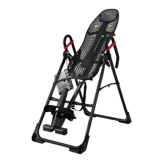
Before Beginning Before reading further, study the drawing below to familiarize yourself with the important components of your new FitSpine R.E.D. inversion table. ® Head Pillow Table Bed Traction Support Handles ™ Hinge Covers 3-Hole Roller Hinges Height-Selector Locking Pin Spreader Arms Main Shaft Angle Tether... -
Page 5: Warning Label Placement
Ankles must be properly secured before use. REPLACE LABEL IF DAMAGED, ILLEGIBLE, OR REMOVED. IA-2007 0611-1 We hope you enjoy your new FitSpine R.E.D. Inversion Table! ® If you have any questions, please contact our Customer Service Department at 1.800.847.0143 or www.teeter-inversion.com. - Page 6 Step Figure 1 Assemble the A-Frame (NX-1110) • Open the A-Frame on the floor and make sure the Spreader Arms are locked open (Figure 1). Right Left • Familiarize yourself with the Front, Back, Left and Right of the A-Frame. You may want to refer back to this diagram for reference throughout the assembly process.
- Page 7 Step 2 Figure 2 Attach the Upper Support Arms to the Table Bed (EP-1300) • Place the Table Bed face down on the floor and push down on the Support Beam, so the two holes align evenly with the holes at the base of the Upper Support Arms (Figure 2). You may have to exert extra pressure to ensure that the Support Beam slides over the rubber spacers.
- Page 8 Step 3 Figure 4 Install the Roller Hinges (F5-1064) onto the Table Bed (EP-1300) • For ease-of-assembly, rest the Table Bed against the Crossbar of the A-Frame (Figure 4). • Open the Cam Locks on each side of the Table Bed (Figure 5). •...
- Page 9 Step 4 Figure 8 Attach the Table Bed (EP-1300) to the A-Frame (NX-1110) • Pick up the Table Bed, holding each side near the Roller Hinges, and stand in front of the A-Frame where the Crossbar is located (refer to Figure 1 to determine A-Frame Front). •...
- Page 10 Step 5 Figure 11 Insert the Main Shaft (NX-1650) into the Table Bed • Loosen the De-Rattler Knob on the Main Shaft Housing. • With the Height Adjustment Settings on the Main Shaft facing up, slide the end of the Main Shaft into the Main Shaft Housing (Figure 11) on the Table Bed.
- Page 11 Step 7 Figure 14 Assemble the Traction Support Handles (FS-1045) onto the A-Frame (NX-1110) ™ • Insert the Left and Right handles into the A-Frame (Figure 14). • Insert the Bolts (IA-1148-B) from the inside of the A-Frame and fasten with the Nuts from the outside of the A-Frame (Figure 15).
- Page 12 • Test the Inversion Table by hand for smooth and steady rotation (Figure 19). • Ensure that all fasteners are secure. • Please complete the warranty registration online at www.teeter-inversion.com. • For your reference, the serial number can be found on the back of the Table Bed.
- Page 13 WARNING If your Teeter Hang Ups Inversion Table looks like either of these images, your table has been misassembled and is unfit for use. Image A demonstrates that the Roller Hinges have been assembled upside down into the Table Bed and must be corrected. Go back to Step 3 for instruction.
- Page 14 Adjustments / Maintenance / Storage Adjustments: Changing the Roller Hinge Setting Figure 20 To adjust the Roller Hinge setting, you’ll need to fully remove the Table Bed from the A-Frame. • Remove the Angle Tether from the U-Bar located on the underside of the Table Bed. •...
- Page 15 30175 Hannover, Germany the UL Listing. U.S. and Foreign Patents Pending. Teeter Hang Ups is a registered trademark of Teeter. Specifications subject to change without notice. © COPYRIGHT 2011 Teeter. International Law Prohibits Any Copying LS-1004 1011-0...
Need help?
Do you have a question about the FitSpine R.E.D. and is the answer not in the manual?
Questions and answers