Table of Contents
Advertisement
Advertisement
Table of Contents

Related Manuals for Samsung SCS-26UC2


Summary of Contents for Samsung SCS-26UC2
- Page 1 User Menual (SCS-26UC2) UbiCell Plus User Guide _...
-
Page 2: Federal Communication Commission Interference Statement
Part 15 of the FCC Rules. Operation is subject to the following two conditions: (1) This device may not cause harmful interference, and (2) this device must accept any interference received, including interference that may cause undesired operation _ © SAMSUNG Electronics Co., Ltd. - Page 3 FCC RF Radiation Exposure Statement: This equipment complies with FCC RF radiation exposure limits set forth for an uncontrolled environment. This equipment should be installed and operated with a minimum distance of 20 centimeters between the radiator and your body.This transmitter must not be co-located or operating in conjunction with any other antenna or transmitter.
-
Page 4: Safety Concerns
Indication for prohibiting an action for a avoid a service failure or damage to the product. system. Note Instruction Indicates additional information as a Indication for commanding a reference. specifically required action. _ © SAMSUNG Electronics Co., Ltd. -
Page 5: Warning
Warning WARNING Power Insert power cord Do not touch the Do not connect many Pull out the power plug tightly and fully into the UbiCell Plus or power devices to a single when the UbiCell Plus is outlet. plug with wet hands. outlet. - Page 6 UbiCell Plus or Failure to do so Moisture in the fire. Failure to do so may cause fire or UbiCell Plus can may cause fire or electric shock. cause a fire and electric shock. electric shocks. _ © SAMSUNG Electronics Co., Ltd.
-
Page 7: Caution
Caution CAUTION Installation/Maintenance Accurately install and Do not spray water Do not install the Do not separate, repair properly use the directly or do not use UbiCell Plus on an or remodel the UbiCell product according to chemical solvents such unstable surface or near Plus arbitrarily. - Page 8 If they are too close, GPS signal can not be normally received. _ © SAMSUNG Electronics Co., Ltd.
- Page 9 50cm apart from the charger provided or router. other LAN devices. activated by Samsung Failure to do so may Electronics. cause the damage to Failure to do so may RF signal interference the product.
- Page 10 Not doing so may cause product malfunction resulting from the rise Failure to do so may cause the of inside temperature. damage to the product. _ © SAMSUNG Electronics Co., Ltd.
- Page 11 Installation/Maintenance GPS antenna detached from the If the UbiCell Plus does not work The UbiCell Plus should be UbiCell Plus always should be for a long time, check the state of registered first. located indoors. LED and call customer service. Your UbiCell Plus will not be able If not, GPS antenna can be This is to prevent malfunctions...
-
Page 12: Table Of Contents
TABLE OF CONTENTS SAFETY CONCERNS Conventions/Symbols .....................4 Warning........................5 Caution ........................7 PREPARATION Congratulations!....................14 About This Guide ....................14 What’s in the box ....................15 Names and Functions of each part...............16 LED.................................16 Connector...............................17 Registering your UbiCell Plus ................20 OVERVIEW _ © SAMSUNG Electronics Co., Ltd. - Page 13 INSTALLING YOUR UBICELL PLUS TROUBLESHOOTING ANNEX A Product Specifications ..................28 UbiCell Plus User Guide _...
-
Page 14: Preparation
UbiCell Plus and the benefits this new UbiCell Plus can provide. Keep this guide handy. You may need to look up instructions for infrequently used features. _ © SAMSUNG Electronics Co., Ltd. -
Page 15: What's In The Box
What’s in the box After purchasing this product, check if the items below are all included in the package. If any item is missing or damaged, contact your dealer: Power Supply and Cord UbiCell Plus Ethernet Cable User Guide UbiCell Plus User Guide _... -
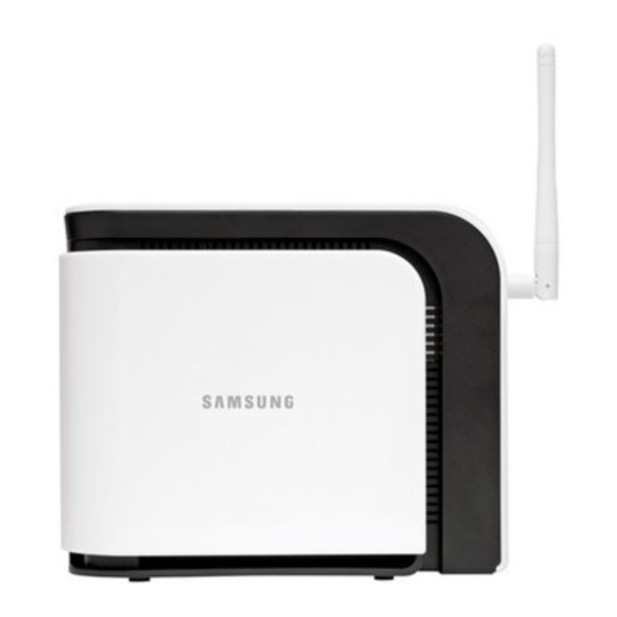
Page 16: Names And Functions Of Each Part
When the internal GPS antenna is not able to detect a stable GPS signal and cannot validate accurate time and location information, it turns red. When the Ethernet cable is normally connected, it turns blue. When there is data traffic, it turns blinking blue. _ © SAMSUNG Electronics Co., Ltd. -
Page 17: Connector
Connector Name Description Antenna Provides omni-directional transmission and reception of signals between the UbiCell Plus and communicating mobile station. Connects the power cable. Connects the Ethernet cable. UbiCell Plus User Guide _... - Page 18 The extension cable that is connected between the UbiCell Plus and detached GPS antenna is 7 meters (about 23 feet) long, providing plenty of flexibility in locating both it and the UbiCell Plus. _ © SAMSUNG Electronics Co., Ltd.
- Page 19 GPS Antenna 1) Turn off the base station. 2) Rotate the antenna down to provide access to the GPS antenna’s protective cover. 3) Firmly press down on the Open button (top of station) 4) Slide the protective cover back to expose the internal GPS mini-coax connector. 5) Connect and secure the GPS antenna to the exposed port by using the GPS cable.
-
Page 20: Registering Your Ubicell Plus
Registering your UbiCell Plus Before installing your UbiCell Plus you need to register. Registering Your UbiCell Plus will not be able to function if the instruction is violated. Your UbiCell Plus should be registered first. _ © SAMSUNG Electronics Co., Ltd. -
Page 21: Overview
OVERVIEW The UbiCell Plus is a system that performs the radio interface with Mobile Stations (MS), and exchanges radio subscriber data and signal data with the MSs under CDMA2000 standards. Home or Office Provider’s Network Security Gateway UbiCell UbiCell Plus User Guide _... - Page 22 2) Install the UbiCell Plus at a distance of more than 30 cm from the walls or other products. 3) The adjustable antenna rotates only 180 degrees. Rotating it beyond that angle may damage the antenna. _ © SAMSUNG Electronics Co., Ltd.
- Page 23 Connecting Ethernet Cables and Power Power Cord Power Supply Ethernet Cable Modem 1) Connect one end of the included Ethernet cable to an open port on the modem. 2) Connect the other end to the WAN port located at the rear of the UbiCell Plus. 3) Plug the power supply connector into the PWR connector located at the rear of the UbiCell Plus.
- Page 24 2) Ethernet cable connector (RJ-45) should be plugged before plugging a DC power cable. Connecting the power 1) Please use a refined accessory and a charger provided or activated by Samsung Electronics. 2) Use only the power supply and cord that are included in the package.
- Page 25 Checking the LED The ‘PWR’ LED on the front of the UbiCell Plus should lit up blue when power is connected normally. Over the next few minutes the ‘WAN’ LED, the ‘GPS’ LED, and the ‘SYS’ LED should all lit up blue. (If after 10 minutes any of the LEDs is not lit up, or is lit up red, see the ‘Troubleshooting’...
-
Page 26: Troubleshooting
Ethernet connection. - Confirm that both ends of the Ethernet cable are securely plugged into the WAN port on the UbiCell Plus and into an open port on the router(or modem). _ © SAMSUNG Electronics Co., Ltd. - Page 27 Ethernet connection, GPS signal, and communication with the system. If the above suggestions did not correct the problem, or you encounter a problem that is not listed here, you can get additional assistance by calling Samsung customer service. UbiCell Plus User Guide _...
-
Page 28: Product Specifications
ANNEX A Product Specifications _ © SAMSUNG Electronics Co., Ltd. - Page 29 The specification of the transmitter and receiver of the UbiCell Plus is described as follows: The items that are not included in the following table should meet the IS-95A/B, IS-2000 standard. Frequencies by Models SCS-26UC2 support 1.9 G band Item Specification...
- Page 30 The specification of the UbiCell Plus power is described as follows. The UbiCell Plus meets the power safety criterion defined in UL60950-1 and EN60950-1. Category Specification Input Voltage AC 110 V Voltage Variation Range (Tolerable error of 100~250 VAC commercial electric power source) _ © SAMSUNG Electronics Co., Ltd.
- Page 31 UbiCell Plus User Guide _...
Need help?
Do you have a question about the SCS-26UC2 and is the answer not in the manual?
Questions and answers