Table of Contents
Advertisement
Quick Links
Advertisement
Table of Contents

Subscribe to Our Youtube Channel
Related Manuals for Furuno NXT-600


Summary of Contents for Furuno NXT-600
-
Page 1: Network Fish Finder
OPERATOR'S MANUAL NETWORK FISH FINDER DFF1-UHD Model www.furuno.com... - Page 3 How to discard a used battery Some FURUNO products have a battery(ies). To see if your product has a battery, see the chap- ter on Maintenance. Follow the instructions below if a battery is used. Tape the + and - terminals of battery before disposal to prevent fire, heat generation caused by short circuit.
- Page 4 A warning label is attached to the equipment. Do not remove the label. If the label is missing Turn off the power immediately if water or illegible, contact a FURUNO agent or dealer leaks into the equipment or an object is about replacement.
- Page 5 SAFETY INSTRUCTIONS Safety instructions for the installer WARNING CAUTION CAUTION The transducer cable must be handled Do not work inside the equipment carefully, following the guidelines unless qualified to do so. below. Electricla shock can occur. • Keep fuels and oils away from the cable.
-
Page 6: Table Of Contents
TABLE OF CONTENTS FOREWORD ........................v SYSTEM CONFIGURATION ..................vi INSTALLATION ...................... 1 1.1 Equipment Lists......................1 1.2 Network Fish Finder ....................2 1.3 Transducer ........................3 1.4 Optional Speed/Temperature Sensors ST-02MSB, ST-02PSB ........3 1.4.1 Mounting considerations..................3 1.4.2 Mounting procedure..................... 3 WIRING ........................ -
Page 7: Foreword
Congratulations on your choice of the FURUNO DFF1-UHD Network Fish Finder. We are confi- dent you will see why the FURUNO name has become synonymous with quality and reliability. Since 1948, FURUNO Electric Company has enjoyed an enviable reputation for quality marine electronics equipment. -
Page 8: System Configuration
SYSTEM CONFIGURATION NavNet Equipment TZT9/14/BB Ethernet HUB HUB-101 NETWORK FISH FINDER DFF1-UHD 12-24 VDC Rectifier PR-62 External Speed/Temperature Sensor ST-02MSB ST-02PSB 100/110/ 220/230 VAC Temperature Sensor Transducer 1ø, 50/60 Hz T-04MSB T-04MTB B265LH B275LH-W CM265LH CM275LH-W... -
Page 9: Installation
INSTALLATION Equipment Lists Standard supply Name Type Code No. Remarks Network Fish Finder DFF1-UHD Spare Parts SP02-05601 001-033-740 1 set Fuse (2 pcs.) Installation Materials CP02-08500 000-011-917 1 set - Power cable assy. (3.5 m) - LAN cable assy. (5 m) - Self-tapping screws Optional supply Name... -
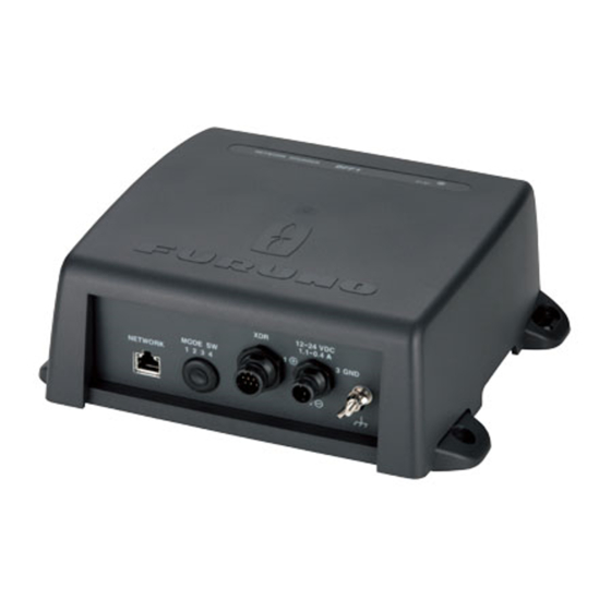
Page 10: Network Fish Finder
1. INSTALLATION Network Fish Finder The network fish finder can be installed on a desktop, deck or on a bulkhead. When selecting a mounting location, keep the following points in mind: • This unit meets the waterproofing standard IP55. However, do not install the unit outdoors. •... -
Page 11: Transducer
1. INSTALLATION Transducer The performance of the fish finder largely depends upon the transducer position. Select a place least affected by air bubbles since turbulence blocks the sounding path. The face of the transducer must be facing the sea bottom in normal cruising trim of the boat. Further, select a place least in- fluenced by engine noise. -
Page 12: Wiring
WIRING Wiring Outline Connect the power cable, transducer cables, sensor cable, network cable and ground wire to their respective locations on the network fish finder. See the next page for how to connect the trans- ducer cable. TZT9/TZT14/ TZTBB MOD-Z072-050+, 5 m To HUB-101 (option: 2/10 m) DFF1-UHD... -
Page 13: Transducer Cable, Cable For External Kp (Option)
2. WIRING Transducer Cable, Cable for External KP (option) If the external KP is not to be connected, do only the applicable procedures in section 2.2.1 and 2.2.2. The KP from an echo sounder or sonar can be connected to this network fish finder to synchronize transmission between the sounder and this network fish finder. - Page 14 2. WIRING How to prepare the cable for the external KP 1. Prepare the PH connector (02-1097, optional supply) as shown below. a) Make the length of the wires of the PH connector 100 mm. b) Remove the sheath from the cores 10 mm. c) Fold back the cores in half.
-
Page 15: How To Connect The Transducer Cable
2. WIRING 2.2.2 How to connect the transducer cable This procedure shows you how to connect the transducer cable. 1. Open the cover - grasp the cover at two sides, spread the cover slightly and lift. 2. Loosen four screws to remove the shield cover. 3. - Page 16 2. WIRING 5. Loosen two screws to unfasten the clamp fixing plate for the transducer cable. Loosen two screws to unfasten cable clamping plate for transducer cable. 6. Pass the transducer cable through the sealing nut and super gland and into the unit. 7.
-
Page 17: How To Connect The Cable For The External Kp
2. WIRING 10. Tighten the sealing nut according to the information in the table below. Clearance between super gland and Transducer Torque sealing nut CM265LH/ 4 mm 1.8 - 2.0 Nm CM275LH-W B265LH/ 2 mm Clearance B275LH-W 11. Reattach the shield cover and close the outer cover. 2.2.3 How to connect the cable for the external KP 1. - Page 18 2. WIRING 4. Tighten the lock nut. 5. Tighten the sealing nut until the clearance between the nut and 4 mm super gland is 4 mm. The torque for the sealing nut is 1.8 - 2.0 6. Position the cable so the vinyl sheath lies in the cable clamp then use the supplied clamp fixing plate and two upset screws to secure the cable.
-
Page 19: Lan Cable
2. WIRING 8. Attach the supplied EMI core (GRFC-10) to the cable for the external KP, approx. 10 mm from the super gland. 10 mm 10 mm Super gland Super gland EMI core EMI core 9. Attach the shield cover and close the cover. LAN Cable Do as follows to connect the supplied LAN cable (MOD-Z072-050+) or the optional LAN cable (MOD-Z072-020+, MOD-Z072-100+). - Page 20 2. WIRING 3. Pass the sealing nut, clamping claw and sealing insert onto the LAN cable in the order shown in the figure below. Connect the cable to the LAN connector. (Note the orientation of the seal- ing insert when passing it onto the cable. Push the cable into the slit in the sealing insert.) LAN cable Sealing insert (Push cable into slit.)
-
Page 21: Initial Settings
INITIAL SETTINGS WARNING Do not open the equipment unless totally familiar with electrical circuits. Only qualified personnel can work inside the equipment. DIP Switch Setting The DIP switch S2 sets up the system according to the equipment connected. In the default setting all switches (1-8) are OFF. -
Page 22: Operation Check
3. INITIAL SETTINGS Host name IP address ES092002 172.031.092.002 ES092003 172.031.092.003 After setting up the transducer at the DFF1-UHD, set the transducer type at the NavNet device. See respective Installation Manual for the procedure. Note: DIP Switch S3 is for factory use. Do not change the settings. Operation Check For NavNet TZtouch, the DFF1-UHD is powered on/off from the ship’s switchboard. -
Page 23: Maintenance
MAINTENANCE NOTICE WARNING Do not apply paint, anti-corrosive sealant or ELECTRICAL SHOCK HAZARD Do not open the equipment. contact spray to coating or plastic parts of the equipment. Only qualified personnel can work inside the equipment. Those items contain organic solvents that can damage coating and plastic parts, especially plastic connectors. -
Page 24: How To Replace The Fuse
If the equipment cannot be powered, the fuse may have blown. Find out the cause for the blown fuse before replacing it. If the fuse blows again after replacement, contact a FURUNO agent or dealer for instructions. -
Page 25: Appendix 1 Jis Cable Guide
EX: TTYCYSLA - 4 MPYC - 4 TTYCSLA-4 Designation type Designation type # of cores # of twisted pairs The following reference table lists gives the measurements of JIS cables commonly used with Furuno products: Core Cable Cable Core Diameter Type... -
Page 26: Appendix 2 Installation Of Transducers
APPENDIX 2 INSTALLATION OF TRANSDUCERS This appendix provides a copy of the installation instructions and Installation supplement for the AIRMAR transducers. OWNER’S GUIDE & INSTALLATION INSTRUCTIONS Thru-Hull with Stem Record the information found on the cable tag for future reference. Part No.________________Date___________Frequency_________kHz Depth Transducer with Temperature Sensor... - Page 27 APPENDIX 2 INSTALLATION OF TRANSDUCERS • Choose a location away from interference caused by power and radiation sources such as: the propeller(s) and shaft(s), pressure waves machinery, other echosounders, and other cables. The lower the noise level, the higher the echosounder gain setting that can be used.
- Page 28 APPENDIX 2 INSTALLATION OF TRANSDUCERS B258, B271W, SS258 (pointed end toward bow) (arrow toward bow) band saw ► cutting table guide Figure 4. Standard Fairing orientation Copyright © 2005- 2011 Airmar Technology Corp. deadrise angle facing forward toward the bow. The long side must be parallel to the centerline of the boat (see Figure 4).
- Page 29 APPENDIX 2 INSTALLATION OF TRANSDUCERS Checking for Leaks 5. Coat a hollow or solid cylinder of the correct diameter with wax and tape it in place. Fill the gap between the cylinder and hull When the boat is placed in the water, immediately check around with casting epoxy.
- Page 30 APPENDIX 2 INSTALLATION OF TRANSDUCERS Avoid Overheating Installation Supplement: CHIRP Transducers 17-573-01 rev. 05 04/01/14 CAUTION: Follow the instructions that came with your transducer. To install a CHIRP transducer in a way other than intended by the manufacturer may lead to the transducer overheating, resulting in transducer failure.
-
Page 31: Appendix 3 Installation Of Temperature Sensors
APPENDIX 3 INSTALLATION OF TEMPERATURE SENSORS ® The installation instructions in this chapter are copied from the manufacturer's (AIRMAR Tech- nology Corporation) installation guide, which is included with your sensor. The model numbers mentioned within the documentation should be read as follows: •... - Page 32 APPENDIX 3 INSTALLATION OF TEMPERATURE SENSORS 9-12 mm (3/8-1/2") pour in larger than the casting hole through the epoxy hull’s outer skin inner skin core hull thickness hull nut hull solid or hollow cylinder outer skin bedding Figure 1. Bedding and installing Figure 2.
- Page 33 APPENDIX 3 INSTALLATION OF TEMPERATURE SENSORS Maintenance & Replacement Aquatic growth can accumulate rapidly on the sensor’s surface reducing its performance within weeks. Clean the surface with a Scotch-Brite ® scour pad and mild household detergent taking care to avoid making scratches. If the fouling is severe, lightly wet sand with fine grade wet/dry paper.
-
Page 34: Installation Instructions
APPENDIX 3 INSTALLATION OF TEMPERATURE SENSORS OWNER’S GUIDE & INSTALLATION INSTRUCTIONS Surface Mount, Analog Record the information found on the cable tag for future reference. Part No._________________Date___________ Temperature Sensor Model T80 Follow the precautions below for optimal product performance and to reduce the risk of property damage, personal injury, and/or death. - Page 35 APPENDIX 3 INSTALLATION OF TEMPERATURE SENSORS Cable Routing & Connecting Mount the sensor near the centerline and close to the bottom of the transom. 1. Route the cable to the instrument, being careful not to tear the cable jacket when passing it through the bulkhead(s) and other Route the sensor cable over the transom, through a drain hole, or parts of the boat.
-
Page 36: Specifications
FURUNO DFF1-UHD SPECIFICATIONS OF NETWORK FISH FINDER DFF1-UHD GENERAL TX frequency 50/200 kHz, alternative transmission Output power 1 kW nominal Amplifier type Straight amplifier (H/L gain switching available) Depth range and Pulse repetition rate (PRR) at 200 kHz, TX rate: 20 Range (m) PRR (times/min, max.) - Page 38 26/Aug/2014 H.MAKI...
- Page 40 When a claim is made, FURUNO has a right to choose whether with other electronic devices. The imported product may also be to repair the product or replace it.
- Page 41 24 months from installation date provided the work is done by Furuno U.S.A., Inc. or an AUTHORIZED Furuno dealer during normal shop hours and within a radius of 50 miles of the shop location.
- Page 42 (title and/or number and date of issue of the standard(s) or other normative document(s)) For assessment, see • Test Report FLI 12-12-121, January 19, 2013 prepared by Furuno Labotech International Co., Ltd. This declaration is issued according to the Directive 2014/30/EU of the European Parliament and of the Council of 26 February 2014 on the harmonisation of the laws of the Member States relating to electromagnetic compatibility.
- Page 44 (Elemental Chlorine Free) The paper used in this manual is elemental chlorine free. FURUNO Authorized Distributor/Dealer 9-52, Ashihara-cho, Nishinomiya, 662-8580, JAPAN A: JAN. 2013 All rights reserved. Printed in Japan E5: JUN. 14, 2017 Pub. No. OME-20400-E5 (MISU) DFF1-UHD...
Need help?
Do you have a question about the NXT-600 and is the answer not in the manual?
Questions and answers