Furuno FCV-627 Operator's Manual
Fish finder
Hide thumbs
Also See for FCV-627:
- Operator's manual (83 pages) ,
- Quick manual (3 pages) ,
- Operator's manual (2 pages)
Table of Contents
Advertisement
Quick Links
Advertisement
Chapters
Table of Contents

Related Manuals for Furuno FCV-627


Summary of Contents for Furuno FCV-627
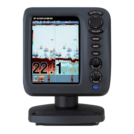
- Page 1 FISH FINDER FCV-627 www.furuno.com...
- Page 2 ・FURUNO Authorized Distributor/Dealer 9-52 Ashihara-cho, Nishinomiya, 662-8580, JAPAN A : OCT 2011 Printed in Japan All rights reserved. Pub. No. OME-23820-A *00017552510* *00017552510* (DAMI ) FCV-627 *00017552510* *00017552510* * 0 0 0 1 7 5 5 2 5 1 0 *...
- Page 3 How to discard a used battery Some FURUNO products have a battery(ies). To see if your product has a battery, see the chapter on Maintenance. Follow the instructions below if a battery is used. Tape the + and - terminals of battery before disposal to prevent fire, heat generation caused by short circuit.
- Page 4 Continued use of the equipment can Adjust the gain correctly. cause fire or electrical shock. Contact a FURUNO agent for service. Incorrect gain may give a wrong depth indication, which could result in a Do not maneuver the vessel based on dangerous situation.
- Page 5 Type: 86-003-1011-3 Do not remove the label. If the label is missing remove cover. No user-serviceable parts inside. Code No.: 100-236-233-10 or damaged, contact a FURUNO agent or dealer about replacement. Safety Instructions for the Installer WARNING CAUTION Turn off the power at the switchboard Do not install the transducer or sensor before beginning the installation.
-
Page 6: Table Of Contents
TABLE OF CONTENTS FOREWORD ........v 2.5 Units Menu........27 2.6 Calib Menu........27 SYSTEM CONFIGURATION ....vi 2.7 Transducer Menu......28 2.8 Demo Menu ......28 OPERATION ......... 1 2.9 Tankenmaru Menu....28 1.1 Control Description......1 1.2 Power On/Off ......2 MAINTENANCE, 1.3 Display Brilliance......2 TROUBLESHOOTING....29 1.4 Display Mode ......2 3.1 Maintenance ......29... -
Page 7: Features
Congratulations on your choice of the FU- mark. RUNO FCV-627 Fish Finder. We are confi- • Bottom discrimination display provides esti- dent you will see why the FURUNO name has mate of bottom composition. become synonymous with quality and reliabil- ity. -
Page 8: System Configuration
GPS Navigator External Equipment Radio Transmitter* Tankenmaru System * Radio transmitter of Water temperature/speed sensor SHIMANO INC. ST-02MSB, ST-02PSB Water temperature sensor T-02MSB, T-02MTB, T-03MSB SHIMANO INC. Transducer make display unit FCV-627 520-5PSD, 520-5MSD, 525-5PWD, Display 525STID-MSD, 525STID-PWD Unit Electric Relay... -
Page 9: Operation
OPERATION Control Description Control Function MENU/ESC • Opens menu. Go back one page in multi-page menu. • Escapes from current operation. • Selects items on the menu. (TrackPad) • Changes settings. • Moves VRM (Variable Range Marker) by using except for nav mode. -
Page 10: Power On/Off
1. OPERATION Power On/Off Display Mode 1. Rotate the MODE knob to open the mode 1. Press the /BRILL key to turn on the setting window, which is displayed for six power. The unit beeps then the startup seconds. screen appears. Nav data mode 1 3-5 seconds later Low frequency zoom mode*... -
Page 11: Dual Frequency Display
1. OPERATION 1.4.3 Zoom displays Zoom mode expands chosen area of the sin- Picture advance speed Gain gle frequency picture. Three modes are avail- able: bottom lock, bottom zoom and marker Alarm Display zoom. The default zoom mode is bottom lock. icon Range mode... -
Page 12: Nav Data Display
1. OPERATION 1.4.4 Nav data display Bottom zoom display The bottom zoom mode expands bottom and The nav data displays appear on the left 2/3 bottom fish on the left-half window. This mode of the screen. Data other than depth requires is useful for tracking bottom contour. -
Page 13: How To Select A Range
1. OPERATION How to Select a Note: The range mode indication, which ap- pears at the top-left corner, may be turned on Range or off with [Header Info] on the [Display] menu. For details, see [Header Info] on page The basic range may be selected in the [Auto] or [Manual] mode. -
Page 14: How To Measure Depth
1. OPERATION How to Measure 1. Press the GAIN knob to open the [Auto Gain] setting window. Depth The VRM (Variable Range Marker) functions to measure the depth to schools of fish, etc. This function is inoperative when a NAV data display is active. -
Page 15: Menu Operating Procedure
1. OPERATION Menu Operating 5. Use to select an option or change a value. Procedure 6. Press the ENTER key (or ) to save the setting. The setting box or window disap- Your fish finder has five main menus: Sound- pears. -
Page 16: Picture Advance Speed
1. OPERATION 2. Select [Shift] and press the ENTER key. Fast Slow Picture and picture advance speed 3. Set the amount of shift desired and press 1. Open the menu, select [Sounder] and the ENTER key. The step for the amount press the ENTER key. -
Page 17: How To Reduce Interference
1. OPERATION 1.11 How to Reduce 1.12 How to Reduce Interference Low Level Noise Interference from other acoustic equipment Low intensity "speckles," caused by sedi- operating nearby or other electronic equip- ments in the water or noise, may appear over ment on your boat may show itself on the dis- most of screen. -
Page 18: How To Erase Weak Echoes
1. OPERATION 1.13 How to Erase 1.14 A-scope Display Weak Echoes The A-scope display shows echoes at each transmission with amplitudes and tone pro- Sediment in the water or reflections from portional to their intensities, on the right 1/3 of plankton may be painted on the display in low the screen. -
Page 19: Fish Information (Accu-Fish)
1. OPERATION 1.15 Fish Information 4. Press the MENU/ESC key twice to close the window. (ACCU-FISH) x1 x1 AUTO_R G:AF AUTO_R G:AF The ACCU-FISH feature measures the length of individual fish and tags the fish with a fish symbol whose size is proportional to the Weak reflection length of the fish. -
Page 20: How To Activate Accu-Fish
1. OPERATION 1.15.1 How to activate 4. Select desired symbol and press the EN- TER key. The size of the symbol is scaled ACCU-FISH according to the estimated length of the ACCU-FISH is inoperative when the trans- fish. ducer type is selected to 600W (on the [Trans- ducer] menu). -
Page 21: Bottom Discrimination Display
1. OPERATION Note 1: You can show the fish info figure alone (without fish symbol) by turning off [Fish Symbols] on the [Display] menu. Note 2: You can show the fish info in small or large characters, with [Info Size] Probability on the [ACCU-FISH] menu. -
Page 22: Alarms
1. OPERATION 1. Open the menu, select the [Display] The bottom fish alarm is given when a fish is menu, select [Bottom Disc.] and press the within the specified distance from the bottom. ENTER key. Available when the bottom lock display is ac- tive. - Page 23 1. OPERATION 1. Open the menu, select [Alarm] and press 3) Repeat steps 1) and 2) to complete the ENTER key. the name. 4) Press the ENTER key to finish. 6. Select [Sound] and press the ENTER key. 7. Select desired alarm sound and press the ENTER key.
- Page 24 1. OPERATION 8) Select the [From] that is below [Depth] Water temperature and press the ENTER key. 1) Select [Inside] or [Outside] as appli- cable and press the ENTER key. 2) Select [From] and press the ENTER key. 3) Enter the starting tem- perature for the alarm ACCU-FISH, Bottom Fish...
-
Page 25: Func Key
1. OPERATION 1.18 FUNC Key Navigation alarms Do the following to set the navigation alarms The FUNC key provides for one-touch call up (speed alarm and arrival alarm). of desired function setting window. 11 items are available: picture advance, shift, interfer- 1. -
Page 26: Waypoints
How to register a way- point Waypoint setting window Note 1: When [TLL] or [FURUNO-TLL] is There are two ways to register a waypoint: di- selected at [TLL Output] on the [NMEA] rectly on the screen or manual input of latitude menu of the [System] menu, the latitude and longitude. -
Page 27: Waypoints
1. OPERATION How to register a waypoint by manual 4. Select item desired and press the ENTER key to show corresponding input box. entry of latitude and longitude 1. Open the menu, select [Data] and press the ENTER key. Waypoint name Latitude Longitude *: Go to WPT... -
Page 28: Waypoint
1. OPERATION How to erase all waypoints 1. Open the menu, select [Data] and press the ENTER key. 2. Select [Delete All WPT] and press the ENTER key. Two-data Three-data Four-data 3. Select [Yes] and press the ENTER key. display display display Items displayable in (1) - (3): speed (STW)*,... -
Page 29: Menu Description
1. OPERATION 1.21 Menu Description SPEED (SOG) This section describes menu items not previ- ously mentioned. For the [System] menu, see chapter 2. Sounder menu Cross-track error Speed over the ground SPEED (STW) WIND True(or Apparent) STBD Speed thru the water Wind speed and direction COMPASS True(or Mag) - Page 30 1. OPERATION 1. Select [White Marker] in the [Sounder] [Bottom Zone]: Set the area where to display menu and press the ENTER key. the bottom echo when selecting the [Auto] mode on the RANGE key. Note: The bottom discrimination feature must be disabled to use this feature.
-
Page 31: Display Menu
1. OPERATION [S] setting, which requires speed data, selects x1 x1 AUTO_R G:AF AUTO_R G:AF the TX rate according to your boat’s speed. A high rate for fast speed; a slow rate for slow Temperature speed. Graph Note: The TX rate may not change when [Pic. Temperature Sync] in the Tankenmaru menu is set to [Yes]. - Page 32 1. OPERATION [Header Info]: Turn the operational info dis- cations in which case they are displayed alter- play (appears at the top on the screen) on or nately every four seconds (default setting). off. Data Box1 display Data Box2 display x1 x1 AUTO_R G:AF AUTO_R G:AF...
- Page 33 1. OPERATION [Trip Source]: Select the source for the trip indication: Select [Own] to use the speed data from the speed sensor connected to this unit, or [NMEA] to use speed data from a naviga- tor. [Temp Source]: Select the source for the wa- ter temperature indication: Select [Own] to use the water temperature data from the wa- ter temperature sensor connected to this unit,...
-
Page 34: System Menu
SYSTEM MENU How to Display the Therefore, change the depth unit before changing the preset ranges. System Menu [Zoom Range]: Select the range The [System] menu mainly consists of items to zoom in the bottom zoom and which do not require regular adjustment. marker zoom modes. -
Page 35: Units Menu
2. SYSTEM MENU Units Menu [Draft]: The default depth display shows the distance from the transducer. If you would rather show the dis- tance from the sea surface, set your ship's draft. [Gain ADJ HF], [Gain ADJ LF]: If the gain is too high or too low, or the gain for the low and high frequencies ap- pears unbalanced, you can... -
Page 36: Transducer Menu
2. SYSTEM MENU Tankenmaru Menu [Zero Line Area]: This fea- ture adjusts the transmission The Tankenmaru system outputs the video line so that the transmission signal from your display unit to the display unit line disappears when the of a Tankenmaru-equipped partner ship, etc., menu item [Zero Line Rejector] is turned on. -
Page 37: Maintenance Troubleshooting
MAINTENANCE, TROUBLESHOOTING How to Clean the Display Unit WARNING Dust or dirt may be removed from the cabinet with a soft cloth. Water-diluted mild detergent ELECTRICAL SHOCK HAZARD Do not open the equipment. may be used if desired. DO NOT use chemi- cal cleaners to clean the display unit;... -
Page 38: How To Replace The Fuse
3. MAINTENANCE, TROUBLESHOOTING How to Replace the Troubleshooting Fuse The table below provides basic troubleshoot- ing procedures which the user may follow to The two fuses (Type: FGBO-A 125V 2A PBF, restore normal operation. Code No.: 000-155-849-10) in the power ca- ble assy. -
Page 39: Diagnostics
3. MAINTENANCE, TROUBLESHOOTING Diagnostics Test item Content If you feel your unit is not working properly, "OK" is shown if check is normal; "NG" conduct the diagnostic test to find the prob- SDRAM for fault. lem. If you cannot restore normal operation, contact your dealer for advice. -
Page 40: Lcd Test
3. MAINTENANCE, TROUBLESHOOTING LCD Test How to Clear the Memory, Reset the This feature tests the LCD for proper display Odometer of colors. Note: To review the seven-tone screen easi- You can restore default menu settings and re- ly, set the brilliance to maximum before start- set the odometer (trip distance indication) as ing the test. -
Page 41: Installation
INSTALLATION Equipment List Standard supply Name Type Code No. Remarks Display Unit CV-627-E With hard cover Select E: English panel CV-627-C C: Chinese panel Installation CP02-07900 1 set • Cable Assy. (Type: KON-004-02M, Materials Code No.: 000-156-405-12) • Self-tapping Screw (Type: 5×25, Code No.: 000-162-610-10, 4 pcs.) Spare Parts SP02-05001... -
Page 42: Display Unit
4. INSTALLATION Display Unit 5. Adjust the angle of the display unit and then tighten the knob to fix the display unit. Mounting considerations Note: When loosening the knob to adjust The display unit can be installed on a desktop, the angle of the display, do not tilt the unit or flush mounted in a console. -
Page 43: 520-5Psd
4. INSTALLATION Thru-hull Mount Transducer Transducer mounting location The thru-hull mount transducer provides the best performance of all, since the transducer protrudes from the hull and the effect of air bubbles and turbulence near the hull skin is Unit: mm reduced. - Page 44 4. INSTALLATION smooth as possible to provide an undis- turbed flow of water around the transduc- Flat Washer er. The fairing block should be smaller than the transducer itself to provide a Rubber Washer Fairing channel to divert turbulent water around Block the sides of the transducer rather than over its face.
-
Page 45: 525-5Pwd
4. INSTALLATION Transom Mount 4. Tape the location shown in the figure be- low. Fill the gap between the wedge front Transducer of the transducer and transom with epoxy material to eliminate any air spaces. The optional transom mount transducer is very commonly employed, usually on relative- 5x20 ly small I/O or outboard boats. -
Page 46: Installation Procedure
4. INSTALLATION Remarks on installation gins in approx. 15-20 minutes so do this step without delay. • Do the installation with the ship moored at a dock, etc. The water depth should be 6.5- 32 feet (2-10 meters). Transducer • Install the transducer in the engine room. •... -
Page 47: Triducer
4. INSTALLATION Case 1 525STID-PWD If the bottom is displayed in reddish brown The optional transom mount triducer the installation is suitable. Go to step 8. 525STID-PWD can be installed by the thru- Case 2 hull method or the inside-hull method. If the bottom is not displayed in reddish brown, go to step 7. - Page 48 4. INSTALLATION Note 1: Do not mount the sensor in an area of 3. Using a 4 mm, #23, or 9/64" bit, drill three turbulence or bubbles: near water intake or holes 22 mm (7/8") deep at the locations discharge openings; behind strakes, struts, indicated.
- Page 49 4. INSTALLATION 19°-22° transom angle (small alumi- Attaching the sensor to the bracket num and fiberglass boats): Position the 1. If the retaining cover near the top of the shim with the tapered end up. bracket is closed, open it by depressing the latch and rotating the cover down- 11°...
- Page 50 4. INSTALLATION Speed/Tempera- 3. On the outside of the hull secure the cable against the transom using the cable ture Sensor clamps. Position a cable clamp 50 mm (option) (2") above the bracket and mark the mounting hole with a pencil. The speed/temperature sensors (ST-02MSB 4.
-
Page 51: Temperature Sen
4. INSTALLATION 8. Launch the boat and check for water leak- Thru-hull mount temperature sensor age around the sensor. T-02MSB, T-03MSB Select a suitable mounting location consider- Locknut ing the following points: • Select a mid boat flat position. Face "notch" toward bow. -
Page 52: T-03Msb
4. INSTALLATION T-03MSB 1. Drill a hole of 25 mm in diameter in the mounting location. 2. Coat holder guide with silicone sealant, and pass gasket, washer and locknut onto holder guide in that order and then tighten the locknut. 3. -
Page 53: Iec 61162-1 Data Sentences
4. INSTALLATION Connect to XDR port Fuse holder at rear of display unit Power supply lines MJ-A10SPF (red and black) Cable tie How to fix fuse holders MJ-A6SRMD MJ-A10SRMD How to ground the display unit Tape connectors with vulcanizing tape and CAUTION then vinyl tape to waterproof them. -
Page 54: Adjustments After Installation
4. INSTALLATION 4.11 Adjustments after Sentence Meaning Water speed and heading. Installation Course over ground and ground speed Language Cross track error Time and date 1. Press the /BRILL key to show the [In- Order of priority stallation] menu. Data Priority Latitude/Longitude: GNS>GGA>RMC>... - Page 55 1. Press the MENU/ESC key. [Off]: Do not output latitude/longitude. [TLL]: Output latitude/longitude. 2. Select [NMEA] from the Installation menu [FURUNO-TLL]: Output latitude/longitude, and press the ENTER key. depth and water temperature. Requires [FU- RUNO-TLL] enabled device. [Port Monitor]: Port Monitor shows the data sentences input to the [12-24 VDC/NMEA] port.
- Page 56 4. INSTALLATION $GPGLL, 1353. 5678, N, 11111. 1111, E, , A, D* 4B<0d><0a> $GNGNS, , 1111. 5751, S, 00013. 5596, E, D, , , , , , *3A<0d><0a> $GPMWV, 111. 11, R, 11. 11, N, A*1B<0d><0a> Press the ENTER key to display the latest data sentence information.
- Page 57 APPENDIX 1 MENU TREE Bold Italic: Default Pic. Advance (x4, x2, x1, 1/2, 1/4, 1/8, 1/16, Stop) Sounder MENU key Zoom Mode (Bottom Lock, Bottom Zoom, Marker Zoom) Shift (0 - 4000 ft, 0 ft) Interference (Auto, High, Medium, Low, Off) Color Erase (0 - 50%, 0%) Clutter (0 - 100%, 0%) White Line (0 - 50%, 0%)
- Page 58 Speed (kn, km/h, mph) Wind (kn, km/h, mph, m/s) Distance (NM, km, SM) NMEA NMEA0183 (Ver 1.5, Ver 2.0, Ver 3.0) NMEA Port (In/Out, In/In) NMEA Output (Off, On) WAAS Setup (Off, WAAS-00 - WAAS-27) TLL Output (Off, TLL, FURUNO-TLL) Port Monitor AP-2...
- Page 59 APPENDIX 1 MENU TREE Calib Draft (-15.0 - +50.0 ft, +0.0 ft) Gain ADJ HF (-20 - +20, +0) Gain ADJ LF (-20 - +20, +0) Temp (-20.0 - +20.0 °F, +0.0 °F) Speed(STW) (-50 - +50 %, +0 %) Fish Size (-80 - +100, +0 %) Water Type (Salt, Fresh) Zero Line...
- Page 60 FURUNO FCV-627 SPECIFICATIONS OF FISH FINDER FCV-627 GENERAL TX frequency 50 kHz and 200 kHz Transmit method Single or dual frequency transmitting Output power 600 W TX rate Max. 3,000 pulse/min Pulse length 0.04 to 3.0 ms Sensitivity 10 dBμV...
- Page 61 FURUNO FCV-627 Output DBS, DBT, DPT, MTW*, RMB*, VHW*, TLL* by key operation *: External data required POWER SUPPLY 12-24 VDC: 1.1-0.5 A ENVIRONMENTAL CONDITION Ambient temperature -15 °C to +55 °C Relative humidity 93 % or less at 40 °C...
- Page 65 INDEX LCD test ............32 LF display............2 ACCU-FISH alarm........15 ACCU-FISH setup........ 11 Arrival alarm ..........17 Maintenance..........29 A-scope display...........10 Marker zoom display ........4 MODE knob...........2 Battery............23 Battery voltage alert ........30 Nav data display........4 Bearing source ..........24 Bottom discrimination display......13 Palette ............23 Bottom fish alarm ........15 Picture advance speed........8 Bottom lock display ........3...
Need help?
Do you have a question about the FCV-627 and is the answer not in the manual?
Questions and answers