Table of Contents
Advertisement
Quick Links
Advertisement
Table of Contents
Troubleshooting

Subscribe to Our Youtube Channel
Related Manuals for Furuno FCV-688


Summary of Contents for Furuno FCV-688
- Page 2 ・FURUNO Authorized Distributor/Dealer 9-52 Ashihara-cho, Nishinomiya, 662-8580, JAPAN A : DEC 2013 Printed in Japan All rights reserved. G : MAR . 15, 2023 Pub. No. OME-23850-G (YOTA ) FCV-688 0 0 0 1 7 8 6 5 8 1 6...
- Page 3 How to discard a used battery Some FURUNO products have a battery(ies). To see if your product has a battery, see the chapter on Maintenance. If a battery is used, tape the + and - terminals of the battery before disposal to prevent fire, heat generation caused by short circuit.
- Page 4 Continued use of the equipment can Incorrect gain may give a wrong depth cause fire or electrical shock. Contact a indication, which could result in a FURUNO agent for service. dangerous situation. Do not maneuver the vessel based on The data presented by this equipment the depth indication alone.
- Page 5 Type: 86-003-1011-3 display unit. Do not remove the label. parts inside. Code No.: 100-236-233-10 If the label is missing or damaged, contact a FURUNO agent or dealer about replacement. Safety Instructions for the Installer WARNING CAUTION Turn off the power at the switchboard Do not install the transducer or sensor before beginning the installation.
-
Page 6: Table Of Contents
TABLE OF CONTENTS FOREWORD ........v SYSTEM MENU ......26 SYSTEM CONFIGURATION ....vi 2.1 How to Display the System Menu ......26 OPERATION ......... 1 2.2 Range Menu ......26 2.3 Key Menu........26 1.1 Control Description......1 2.4 Language Menu ......26 1.2 Power On/Off ......2 2.5 Units Menu........27 1.3 Display Brilliance......2 2.6 Calib Menu........27... -
Page 7: Foreword
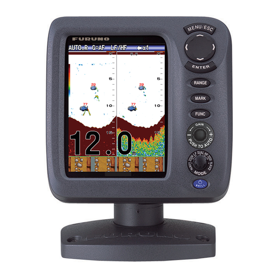
LCD. Disclosure of Information about China Features RoHS The FURUNO FCV-688 is a dual frequency With regards to China RoHS information for (50 kHz and 200 kHz) Fish Finder. our products, please refer to our website Comprised of a display unit and a transducer, (www.furuno.com). -
Page 8: System Configuration
SYSTEM CONFIGURATION For wiring, see the interconnection diagram at the back of this manual. FCV-688 DISPLAY UNIT CV-688-E 12-24 VDC GPS Navigator External Equipment : Standard equipment Water temperature/speed sensor : Optional equipment ST950-FJ46-1, ST950-FJ46-2 : Local supply Temperature sensor... -
Page 9: Operation
OPERATION Control Description Control Function MENU/ESC • Opens menu. Goes back one page in multi-page menu. • Escapes from current operation. • Selects items on the menu. (TrackPad) • Changes settings. • Moves VRM (Variable Range Marker) by using except for nav mode. -
Page 10: Power On/Off
1. OPERATION Power On/Off Display Mode 1. Rotate the MODE knob to open the mode 1. Press the /BRILL key to turn on the setting window, which is displayed for six power. The unit beeps then the startup seconds. screen appears. Nav data mode 1 3-5 seconds later Low frequency zoom mode*... -
Page 11: Dual Frequency Display
1. OPERATION 1.4.3 Zoom displays Picture advance Zoom mode expands chosen area of the sin- speed Gain gle frequency picture. Three modes are avail- Alarm Display able: bottom lock, bottom zoom and marker Range mode icon zoom. The default zoom mode is bottom lock. x1 x1 AUTO_R G:AF AUTO_R G:AF... -
Page 12: Nav Data Display
1. OPERATION 1.4.4 Nav data display Bottom zoom display The bottom zoom mode expands bottom and The nav data displays appear on the left 2/3 bottom fish on the left-half window. This mode of the screen. Data other than depth requires is useful for tracking bottom contour. -
Page 13: How To Select A Range
1. OPERATION How to Select a 3. For [Manual], use the RANGE key (or ) to select the range. Range Basic Range The basic range may be selected in the [Auto] Unit or [Manual] mode. 1000 Note: The RANGE key is inoperative when the bottom discrimination feature is active. -
Page 14: How To Measure Depth
1. OPERATION How to Measure Depth The VRM (Variable Range Marker) functions to measure the depth to schools of fish, etc. This function is inoperative when a NAV data display is active. Too high Correct Too low 1. Use to place the VRM on the ob- 1. -
Page 15: Menu Operating Procedure
1. OPERATION Menu Operating 5. Use to select an option or change a value. Procedure 6. Press the ENTER key (or ) to save the setting. The setting box or window disap- Your fish finder has five main menus: Sound- pears. -
Page 16: Picture Advance Speed
1. OPERATION 2. Select [Shift] and press the ENTER key. Fast Slow 1. Open the menu, select [Sounder] and 3. Set the amount of shift desired and press press the ENTER key. the ENTER key. The step for the amount 2. -
Page 17: How To Reduce Interference
1. OPERATION 1.11 How to Reduce 1.12 How to Reduce Interference Low Level Noise Interference from other acoustic equipment Low intensity "speckles," caused by sedi- operating nearby or other electronic equip- ments in the water or noise, may appear over ment on your boat may show itself on the dis- most of the screen. -
Page 18: How To Erase Weak Echoes
1. OPERATION 1.13 How to Erase 1.14 A-scope Display Weak Echoes The A-scope display shows echoes at each transmission with amplitudes and tone pro- Sediment in the water or reflections from portional to their intensities, on the right 1/3 of plankton may be painted on the display in low the screen. -
Page 19: Fish Information (Accu-Fish ™ )
1. OPERATION 1.15 Fish Information 4. Press the MENU/ESC key twice to close the window. ™ (ACCU-FISH x1 x1 AUTO_R G:AF AUTO_R G:AF ™ The ACCU-FISH feature measures the length of individual fish and tags the fish with a fish symbol whose size is proportional to the Weak reflection (small school of length of the fish. -
Page 20: How To Activate Accu-Fish
1. OPERATION difference in both sensitivity and the according to the estimated length of the echoes viewed. fish. Striped Solid Circle Square 1.15.1 How to activate Large fish symbol ™ ACCU-FISH (more than 50 cm, or more than 20 inches) 1. -
Page 21: Bottom Discrimination Display
1. OPERATION 1.16 Bottom Discrimi- nation Display The bottom discrimination display analyzes the bottom echo to categorize bottom hard- Probability ness in one of four types (rocks, gravel, sand, mud) and shows the results in a colorful Bottom graphic display. A transducer or triducer that discrimination supports the bottom discrimination display is Sand... -
Page 22: Alarms
1. OPERATION 1. Open the menu, select the [Display] ™ zone. Available when the ACCU-FISH fea- menu, select [Bottom Disc.] and press the ture is active. ENTER key. The fish school alarm alerts you to a school of fish in the set alarm zone. The bottom fish alarm is given when a fish is within the specified distance from the bottom. - Page 23 1. OPERATION 1. Open the menu, select [Alarm] and press 3) Repeat steps 1) and 2) to complete the ENTER key. the name. 4) Press the ENTER key to finish. 6. Select [Sound] and press the ENTER key. 7. Select desired alarm sound and press the ENTER key.
- Page 24 1. OPERATION 8) Select the [From] that is below [Depth] Water temperature and press the ENTER key. 1) Select [Inside] or [Outside] as appli- cable and press the ENTER key. 2) Select [From] and press the ENTER key. 3) Enter the starting tem- perature for the alarm ACCU-FISH, Bottom Fish...
-
Page 25: Func Key
1. OPERATION 1.18 FUNC Key Navigation alarms Do the following to set the navigation alarms The FUNC key provides for one-touch call up (speed alarm and arrival alarm). of desired function setting window. 11 items are available: picture advance, shift, interfer- 1. -
Page 26: Waypoints
There are two ways to register a waypoint: di- rectly on the screen or manual input of latitude Note 1: When [TLL] or [FURUNO-TLL] is and longitude. selected at [TLL Output] on the [NMEA] menu of the [System] menu, the latitude... -
Page 27: How To Edit Registered Waypoints
1. OPERATION How to register a waypoint by manual 5. Enter name or latitude and longitude as applicable. entry of latitude and longitude 6. Press the MENU/ESC key to register the 1. Open the menu, select [Data] and press window. the ENTER key. -
Page 28: How To Set Destination Waypoint
1. OPERATION How to erase all waypoints 3. Use to select the item to display. The items that can be displayed depend 1. Open the menu, select [Data] and press on the screen division. the ENTER key. 2. Select [Delete All WPT] and press the ENTER key. -
Page 29: Menu Description
1. OPERATION 1.21 Menu Description SPEED (SOG) This section describes menu items not previ- ously mentioned. For the [System] menu, see chapter 2. Sounder menu Cross-track error Speed over the ground WIND True(or Apparent) SPEED (STW) STBD Speed thru the water Wind speed and direction COMPASS True(or Mag) - Page 30 1. OPERATION [White Marker]: Display the selected echo [Bottom Zone]: Set the area where to display color in white. the bottom echo when selecting the [Auto] mode on the RANGE key. 1. Select [White Marker] in the [Sounder] menu and press the ENTER key. Note: The bottom discrimination feature must be disabled to use this feature.
- Page 31 1. OPERATION The [S] setting, which requires speed data, function is inoperative with the single frequen- selects the TX rate according to your boat’s cy, nav data mode or A-scope display. speed. A high rate for fast speed; a slow rate 1.
- Page 32 1. OPERATION [Header Scale]: The header scale (below the 1) Select [Nav Data1] and press the ENTER header info) provides an estimate of time or key. distance. • Time: An orange bar and a “blank” bar scroll across the screen for 30 seconds each.
- Page 33 1. OPERATION [Temp Source]: Select the source for the wa- ter temperature indication: Select [Own] to use the water temperature data from the wa- ter temperature sensor connected to this unit, or [NMEA] to use the water temperature data from a navigator. [Speed Source]: Select the source for speed.
-
Page 34: System Menu
SYSTEM MENU How to Display the Therefore, change the depth unit before changing the preset ranges. System Menu Note: The deepest detection range of Auto The [System] menu mainly consists of items Range is the largest setting of [Range 1] to which do not require regular adjustment. -
Page 35: Units Menu
2. SYSTEM MENU Calib Menu [Language]: The system language is avail- able in English, and European and Asian lan- guages. To change the language, select the appropriate language and press the ENTER key. Units Menu [Draft]: The default depth display shows the distance [Depth]: Select unit of depth measurement, from the transducer. -
Page 36: Transducer Menu
2. SYSTEM MENU [Fish Size]: Compensate for wrongful indica- Bottom lock display tion of fish size. AUTO_R G:AF AUTO_R G:AF BL-LF BL-LF x1 x1 Compensation size Setting value Double +100% +50% -50% -65% -75% -80% [Water Type]: Select the water type with which to use the equipment, from [Salt] or [Fresh]. -
Page 37: Maintenance, Troubleshooting
MAINTENANCE, TROUBLE- SHOOTING How to Clean the WARNING Display Unit ELECTRICAL SHOCK HAZARD Dust or dirt may be removed from the cabinet Do not open the equipment with a soft cloth. Water-diluted mild detergent (other than when installing flush may be used if desired. DO NOT use chemi- mount hanger cover). -
Page 38: How To Replace The Fuse
3. MAINTENANCE, TROUBLESHOOTING How to Replace the Troubleshooting Fuse The table below provides basic troubleshoot- ing procedures which the user may follow to The two fuses (Type: FGBO-A 125V 2A PBF, restore normal operation. Code No.: 000-155-849-10) in the power ca- ble assy. -
Page 39: Diagnostics
3. MAINTENANCE, TROUBLESHOOTING Diagnostics Test item Content If you feel your unit is not working properly, "OK" is shown if check is normal; "NG" conduct the diagnostic test to find the prob- SDRAM for fault. lem. If you cannot restore normal operation, contact your dealer for advice. -
Page 40: Lcd Test
3. MAINTENANCE, TROUBLESHOOTING LCD Test How to Clear the Memory, Reset the This feature tests the LCD for proper display Odometer of colors. Note: To review the seven-tone screen easi- You can restore default menu settings and re- ly, set the brilliance to maximum before start- set the odometer (trip distance indication) as ing the test. -
Page 41: Installation
INSTALLATION Equipment List Standard supply Name Type Code No. Remarks Display Unit CV-688-E 000-024-880 With hard cover Select -E: English panel CV-688-C 000-024-881 -C: Chinese panel Installation CP02-07900 000-014-312 1 set • Cable Assy. (Type: KON-004-02M, Materials Code No.: 000-156-405-12) •... -
Page 42: Display Unit
4. INSTALLATION ** Use of the extension cable may cause the following problems: • Reduced detection ability ™ • Wrong ACCU-FISH information (fish length smaller than actual length, fewer fish detec- tions, error in individual fish detection). • Wrong speed data •... - Page 43 4. INSTALLATION The transducer should, therefore, be locat- Procedure for installation of the thru-hull ed in a position where water flow is the mount transducer (for 520-5PSD/ smoothest. Noise from the propellers also 520-5MSD) adversely affects performance and the 1. With the boat hauled out of the water, transducer should not be mounted nearby.
-
Page 44: Transom Mount Transducer
4. INSTALLATION Transom Mount Flat Washer Transducer Rubber Washer Fairing Block The optional transom mount transducer is very commonly employed, usually on relative- ly small I/O or outboard boats. Do not use this method on an inboard motor boat because turbulence is created by the propeller ahead Hull of the transducer. -
Page 45: How To Mount A Thru-Hull Transducer Inside The Hull
4. INSTALLATION How to Mount a 4. Tape the location shown in the figure be- low. Fill the gap between the wedge front Thru-hull Trans- of the transducer and transom with epoxy ducer Inside the material to eliminate any air spaces. Hull 5x20 The thru-hull mount transducer may also be... - Page 46 4. INSTALLATION Installation procedure 6) Set the [TX Power] to [10%]. 7) Press the MENU/ESC key two times. If the thickness of the hull varies, then the at- tenuation of the ultrasound pulse may vary. 8) Check if the bottom echo appears on Select a location where the attenuation is the the display.
-
Page 47: Triducer
4. INSTALLATION Triducer 8. Turn the power on and change the menu setting as follows: DO NOT overtighten screws. They may be 1) Push the MENU/ESC key to show the damaged. main menu. 2) Select [Sounder] menu. 525T-BSD, 526TID-HDD 3) Set the [TX Power] to [Auto]. For details of the installation, see the manual 4) Push the MENU/ESC key to show the of the triducer. - Page 48 4. INSTALLATION • Drill bit: Note 4: For twin drive boat, mount between For bracket holes: 4 mm, #23, or 9/64" the drives. For fiberglass hull: chamfer bit (preferred), 6 mm, or 1/4" Installation of bracket For transom hole: 9 mm or 3/4" (optional) 1.
- Page 49 4. INSTALLATION "Attaching the sensor to the bracket", be- 4. Repeat step 1 to ensure that the angle of fore proceeding with "Adjusting". the sensor is correct. Note: Do not position the sensor farther Adjustments into the water than necessary to avoid in- creasing drag, spray, and water noise 1.
-
Page 50: Speed/Temperature Sensor (Option)
4. INSTALLATION 4. Rotate the sensor downward until the bot- 8. Position the two cable clamps and fasten tom snaps into the bracket. them in place. If used, push the cable cov- er over the cable and screw it in place. 5. -
Page 51: Wiring
4. INSTALLATION Wiring 4. Apply marine sealant to the flange of the sensor. The height of the coat should be Connect the cable assy. (supplied) to the approx. 6 mm. 12-24 VDC/NMEA port, and the transducer 5. Pass the sensor casing through the hole. cable to the XDR port. - Page 52 4. INSTALLATION Note 1: Attach the MJ cable cap (supplied) to External equipment the transducer cable to protect the connector The [12-24 VDC/NMEA] port is commonly when the display unit is removed from the used for connection of external equipment boat.
-
Page 53: Iec 61162-1 Data Sentences
4. INSTALLATION IEC 61162-1 Data Order of priority Sentences Data Priority The table below shows the data sentences Latitude/Longitude: GNS>GGA>RMC> RMA>GLL which can be input to and output from your fish finder. The transmission speed for both Course (true): VTG>RMC>RMA input and output is 4,800 bps. -
Page 54: Adjustments After Installation
4. INSTALLATION 4.10 Adjustments after 2. Select your transducer and press the EN- TER key. Select [600W] for the 600 W Installation transducer which is not listed in the fol- lowing table. Language Transducer (option) 520-5PSD, 520-5MSD, 520-PLD, 1. Press the /BRILL key to show the 525-5PWD, 525T-PWD, 525T-BSD, 525T-LTD/12, 525T-LTD/20,... - Page 55 [TLL Output]: Output the position specified by the MARK key to the plotter connected. [Off]: Do not output latitude/longitude. [TLL]: Output latitude/longitude. [FURUNO-TLL]: Output latitude/longitude, depth and water temperature. Requires [FU- RUNO-TLL] enabled device. [Port Monitor]: Port Monitor shows the data sentences input to the [12-24 VDC/NMEA] port.
-
Page 56: Menu Tree
APPENDIX 1 MENU TREE Bold Italic: Default Pic. Advance (x4, x2, x1, 1/2, 1/4, 1/8, 1/16, Stop) Sounder MENU key Zoom Mode (Bottom Lock, Bottom Zoom, Marker Zoom) Shift (0 - 4000 ft, 0 ft) Interference (Auto, High, Medium, Low, Off) Color Erase (0 - 50%, 0%) Clutter (0 - 100%, 0%) White Line (0 - 50%, 0%) - Page 57 Speed (kn, km/h, mph) Wind (kn, km/h, mph, m/s) Distance (NM, km, SM) NMEA NMEA0183 (Ver 1.5, Ver 2.0, Ver 3.0) NMEA Port (In/Out, In/In) NMEA Output (Off, On) WAAS Setup (Off, WAAS-00 - WAAS-27) TLL Output (Off, TLL, FURUNO-TLL) Port Monitor AP-2...
- Page 58 APPENDIX 1 MENU TREE Calib Draft (-15.0 - +50.0 ft, +0.0 ft) Gain ADJ HF (-20 - +20, +0) Gain ADJ LF (-20 - +20, +0) Temp (-20.0 - +20.0 °F, +0.0 °F) Speed(STW) (-50 - +50 %, +0 %) Fish Size (-80 - +100, +0 %) Water Type (Salt, Fresh) Zero Line...
-
Page 59: (525T-Ltd/12, 525T-Ltd/20
APPENDIX 2 INSTALLATION OF TRANSDUCER (525T-LTD/12, 525T-LTD/20) This appendix provides a copy of the installation instructions for AIRMAR transducer. 525T-LTD/12 and 525T-LTD/20 corresponds to B60, SS60-SLTD/12 and SS60-SLTD/20 to SS60. Thru-Hull Record the information found on the cable tag for future reference. Tilted Element Transducer Part No. - Page 60 APPENDIX 2 INSTALLATION OF TRANSDUCER (525T-LTD/12, 525T-LTD/20) Mounting Location Identify Your Model CAUTION: Do not mount near water intake or discharge The model name is printed on the cable tag. openings or behind strakes, fittings, or other hull irregularities. Cored Fiberglass Hull Model Hull Outside Hull...
- Page 61 APPENDIX 2 INSTALLATION OF TRANSDUCER (525T-LTD/12, 525T-LTD/20) P19 housing B150M, B619, SS150M, or SS619 B60, B75H/M/L, or SS60 Wrench Wrench Housing flat (2) flat (2) Wrench Housing Housing flat (2) Hull nut Hull nut Hull nut Spacer Washer Washer Washer Hull Hull Hull...
- Page 62 APPENDIX 2 INSTALLATION OF TRANSDUCER (525T-LTD/12, 525T-LTD/20) 6. Sand and clean the area around the hole, inside and 9-12 mm outside, to ensure that the marine sealant will adhere (3/8-1/2") larger properly to the hull. If there is any petroleum residue inside than the hole Pour in the hull, remove it with either mild household detergent or...
- Page 63 APPENDIX 3 INSTALLATION OF TEM- PERATURE SENSORS © The installation instructions in this chapter are copied from the manufacturer's (AIRMAR Tech- nology Corporation) installation guide, which is included with your sensor. The model numbers mentioned within the documentation should be read as follows: •T42 →...
-
Page 64: Installation Of Temperature Sensors
APPENDIX 3 INSTALLATION OF TEMPERATURE SENSORS 9-12 mm (3/8-1/2") pour in larger than the casting hole through the epoxy hull’s outer skin inner skin core hull thickness hull nut hull solid or hollow cylinder outer skin bedding Figure 1. Bedding and installing Figure 2. - Page 65 APPENDIX 3 INSTALLATION OF TEMPERATURE SENSORS Maintenance & Replacement Aquatic growth can accumulate rapidly on the sensor’s surface reducing its performance within weeks. Clean the surface with a ® Scotch-Brite scour pad and mild household detergent taking care to avoid making scratches. If the fouling is severe, lightly wet sand with fine grade wet/dry paper.
- Page 66 APPENDIX 3 INSTALLATION OF TEMPERATURE SENSORS OWNER’S GUIDE & INSTALLATION INSTRUCTIONS Surface Mount, Analog Record the information found on the cable tag for future reference. Part No._________________Date___________ Temperature Sensor Model T80 Follow the precautions below for optimal product performance and to reduce the risk of property damage, personal injury, and/or death.
- Page 67 APPENDIX 3 INSTALLATION OF TEMPERATURE SENSORS Cable Routing & Connecting Mount the sensor near the centerline and close to the bottom of the transom. 1. Route the cable to the instrument, being careful not to tear the cable jacket when passing it through the bulkhead(s) and other Route the sensor cable over the transom, through a drain hole, or parts of the boat.
- Page 68 FURUNO FCV-688 TX frequency 50 kHz and 200 kHz Transmit method Single or dual frequency transmitting Output power 600 W TX rate Max. 3,000 pulse/min Pulse length 0.04 to 3.0 ms Sensitivity 10 dB V Display system 5.7-inch color LCD, 87 mm (W) x 116 mm (H), 480 x 640 dots...
- Page 69 FURUNO FCV-688 Output DBS, DBT, DPT, MTW*, RMB*, VHW*, TLL* by key operation *: External data required 12-24 VDC: 1.1-0.5 A Ambient temperature -15 °C to +55 °C Relative humidity 93 % or less at 40 °C Degree of protection...
- Page 70 FP02-05801 ACCESSORIES 001-260-170-00 工事材料 INSTALLATION MATERIALS ケーブル(クミヒン) KON-004-02M CABLE ASSEMBLY 000-156-405-14 工事材料 CP02-07901 INSTALLATION MATERIALS 001-384-060-00 図書 DOCUMENT 取扱説明CD FCV-688 O/M *CD-ROM* OPERATOR'S MANUAL CD 000-178-829-1* 装備要領(英) E22-01301-* INSTALLATION GUIDE (EN) 000-178-662-1* (略図の寸法は、参考値です。 DIMENSIONS IN DRAWING FOR REFERENCE ONLY.) C2385-Z01-E...
-
Page 74: Index
INDEX LCD test ............32 LF display............2 ACCU-FISH alarm........15 ACCU-FISH setup........ 11 Arrival alarm ..........17 Maintenance..........29 A-scope display...........10 Marker zoom display ........4 MODE knob...........2 Battery............23 Battery voltage alert ........30 Nav data display........4 Bearing source ..........24 Bottom discrimination display......13 Palette ............23 Bottom fish alarm ........15 Picture advance speed........8 Bottom lock display ........3...
Need help?
Do you have a question about the FCV-688 and is the answer not in the manual?
Questions and answers