
Related Manuals for Furuno FCV-1900


Summary of Contents for Furuno FCV-1900
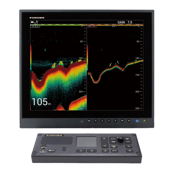
- Page 1 OPERATOR'S MANUAL FISH FINDER HI-RES FISH FINDER FISH SIZE INDICATOR FCV-1900 FCV-1900B FCV-1900G Model (Product Name: FISH FINDER) www.furuno.com...
- Page 2 ・FURUNO Authorized Distributor/Dealer 9-52 Ashihara-cho, Nishinomiya, 662-8580, JAPAN A : APR 2015 Printed in Japan All rights reserved. B : MAY 22, 2015 Pub. No. OME-23860-B ( REFU ) FCV-1900/1900B/1900G 0 0 0 1 9 0 5 0 0 1 1...
- Page 3 How to discard a used battery Some FURUNO products have a battery(ies). To see if your product has a battery, see the chapter on Maintenance. Follow the instructions below if a battery is used. Tape the + and - terminals of battery before disposal to prevent fire, heat generation caused by short circuit.
- Page 4 Continued use of the equipment can Do not operate the equipment with cause fire or electrical shock. Contact a wet hands. FURUNO agent for service. Electrical shock can result. Use only the specified power and Use the proper fuse. signal cable.
- Page 5 The unit may be damaged. Warning Label Warning label is attached to the Processor Unit. Do not remove the label. If the label is missing or illegible, contact a FURUNO agent or dealer about replacement. DANGER Electrical shock hazard. Do not remove cover.
-
Page 6: Table Of Contents
TABLE OF CONTENTS FOREWORD ........................vi SYSTEM CONFIGURATION ..................viii OPERATION ......................1-1 1.1 Control Description..................... 1-1 1.2 How to Turn the Power On or Off................1-2 1.3 How to Adjust Display Brilliance and Key Backlighting ..........1-3 1.4 How to Select Display Mode ..................1-3 1.4.1 Single frequency display ................ - Page 7 TABLE OF CONTENTS 1.27 Menu Description......................1-37 1.27.1 [Sounder] menu....................1-37 1.27.2 [Display] menu....................1-38 1.27.3 [Measurement] menu ...................1-39 1.27.4 [Data] menu....................1-40 SYSTEM MENU .....................2-1 2.1 How to Open the [System] Menu................2-1 2.2 [User] Menu ........................2-1 2.3 [Range] Menu ......................2-4 2.4 [TX/RX] Menu ......................2-5 2.5 [Key] Menu .........................2-7 2.6 [Language] Menu......................2-7 2.7 [Units] Menu .......................2-7...
-
Page 8: Foreword
Features The FCV-1900 series are dual frequency Fish Finders. Comprised of a control unit, processor unit and transducer (optional or locally supply), the FCV-1900 series show echo-gram (echo) on a monitor (locally supply). The FCV-1900 series have three models: FCV-1900, FCV-1900B and FCV-1900G. - Page 9 The program(s) is/are free software(s), and you can copy it and/or redistribute it and/or modify it under the terms of the GPL version 2.0 or LGPL version 2.0 as published by the Free Software Foundation. Please access to the following URL if you need source codes: https:// www.furuno.co.jp/cgi/cnt_oss_e01.cgi.
-
Page 10: System Configuration
SYSTEM CONFIGURATION Monitor USB connector Ethernet HUB converter (for brill-control) HUB-101 Network Fish Finder External KP DFF series, BBDS1 Processor Unit Net Sonde FCV-1901 Interface Unit NMEA0183 device FCV-1903 (Sonar, Current Indicator Satellite Compass Telesounder* INTERFACE UNIT FCV-1903 Chart Plotter, etc.) TS-80M2, TS-7100 Tankenmaru System*... -
Page 11: Operation
• Move the fish size histogram window when the function of the touchpad Touchpad is to move the fish size histogram window. For FCV-1900 and FCV-1900B • Move the VRM (Variable Range Marker) when VRM key is in the VRM mode. -
Page 12: How To Turn The Power On Or Off
A beep sounds and the display changes in the following sequence: FURUNO display → model display, then the last-used display is shown. When the key brilliance is set to other than “0”, the power lamp above the key lights. -
Page 13: How To Adjust Display Brilliance And Key Backlighting
How to Adjust Display Brilliance and Key Back- lighting Adjust the display brilliance and key backlighting as follows. The display brilliance con- trol is effective for these FURUNO monitors: MU-190, MU-190V, MU-150HD, MU- 190HD, MU-231. 1. Press the key to show the brilliance adjustment Brill window. -
Page 14: Single Frequency Display
1. OPERATION Picture advance speed Alrarm icon From left: Screenshots taken/ Internal fish finder, Total no. of screenshots external fish finder, Function of the ENTER knob telesounder 0/99 VRM 0.0 Stabilization icon: Appears when the LF: 2.0 LF: 2.0 heaving Minute marker* Transmission line compensasion is... -
Page 15: Dual Frequency Display
1. OPERATION 1.4.2 Dual frequency display The low frequency echo appears on the left; the high frequency echo on the right. This display is useful for comparing underwater conditions with two different frequencies. 0/99 VRM 0.0 LF: 2.0 HF: 2.0 Low frequency High frequency Detection... -
Page 16: Bottom Zoom Display
1. OPERATION Bottom zoom display This mode expands bottom and bottom fish on the left-half window, and is useful for determining bottom contour. When the bottom depth increases, the display automati- cally shifts to keep the bottom echo at the lower part of the screen. Bottom zoom display Single freq. -
Page 17: Bottom Discrimination Display
1. OPERATION Bottom discrimination display The bottom discrimination display has two modes: Bottom discrimination 1/2 and Bot- tom discrimination 1/3. For how to change the mode, see page 2-4. • Bottom discrimination 1/2 display: The bottom discrimination 1/2 screen shows the single frequency echo on the right half of the screen and the bottom discrimination display occupies the left half of the screen. -
Page 18: User 1 And 2 Displays
1. OPERATION 1.4.4 User 1 and 2 displays The user displays let you customize displays as desired. Two displays are provided and the default settings for each are User 1 display: This screen is split vertically three ways and is comprised of LF, HF and MIX displays. -
Page 19: How To Adjust The Range
2. Rotate the ENTER knob to select the display range. The current setting value appears at the upper right of the display. Note 1: For FCV-1900 and FCV-1900B, you can select the display range by pressing key. Note 2: Basic ranges may be preset as desired, on the [Range] menu (see ssection 2.3). -
Page 20: Shifting The Range
1. OPERATION Shifting the Range The basic range and range shifting functions used together give you the means to se- lect the depth you can see on the screen. The basic range can be thought of as pro- viding a “window” into the water column and range shifting as moving the “window” to the desired depth. -
Page 21: Measuring Depth
1. OPERATION Measuring Depth The VRM (Variable Range Marker) measures the depth to a school of fish, etc. 1. Press the VRM key to assign the VRM 0/99 VRM 37.5 control function to the ENTER knob. HF: 2.0 2. Rotate the ENTER knob to place the VRM Depth VRM on the object to measure depth. -
Page 22: Menu Operating Procedure
1. OPERATION rotation moves the screen rightward. Rotate the ENTER knob hard-over to the clockwise direction to shown the current echo screen. How to deactivate the scroll back mode 1. Rotate the ENTER knob hard-over to the clockwise direction or long push the EN- TER knob to shown the current echo screen. - Page 23 1. OPERATION 5. Change the setting. For setting window or box 1) Rotate the ENTER knob to select a menu item. 2) Push the ENTER knob to enter the setting. The setting window or box disappears. To escape without changing setting, press the MENU/ESC key instead of the knob.
-
Page 24: Fish Size Histogram (Fcv-1900G Only)
1. OPERATION 1.12 Fish Size Histogram (FCV-1900G Only) The fish size histogram window shows 0/99 VRM 0.0 approximate fish size in the dense fish 0 0 0 0 LF: 2.0 HF: 2.0 HF: 2.0 HF 2 0 school The fish size histogram window can be displayed on the dual frequency and user display. -
Page 25: How To Interpret The Fish Size Histogram Window
1. OPERATION 2) Select [Graph], then push the ENTER knob. 4. Select [Graph Style], then push the ENTER knob. 5. Select [Horizontal] or [Vertical], then push the ENTER knob. [inch] AVG:34 DATA:186 AVG:34 DATA:186 [inch] [Horizontal] [Vertical] 6. Press the MENU/ESC key several times to close the menu. Note: To close the fish size histogram window, set [ACCU-FISH] to [Off]. -
Page 26: How To Set Measuring Area For Fish Size Histogram (Fcv-1900G Only)
1. OPERATION 3. Select [Graph Location], then push the ENTER knob. 4. Select the location of the window, then push the ENTER knob. 5. Press the MENU/ESC key several times to close the menu. How to move the window to the desired location 1. -
Page 27: Measuring Fish In A Specific Depth Range
1. OPERATION 1.13.2 Measuring fish in a specific depth range 1. Press the key several times to change the measuring mode to the [Specific Range] mode. 0/99 VRM 0.0 LF: 2.0 HF: 2.0 Measuring Measuring 4 4 0 area area Measurement marker Measurement marker (yellow frame) -
Page 28: Measuring Fish In A Specific Area
1. OPERATION 1.13.4 Measuring fish in a specific area 1. Press the key several times to the [Specific Area] measuring mode. 0/99 VRM 0.0 LF: 2.0 HF: 2.0 Measuring Measuring area area Measurement marker Measurement marker (yellow/orange frame) (yellow/orange frame) 47.6 47.6 2. -
Page 29: How To Replay A Screenshot
1. OPERATION • Delete unnecessary files (see section 1.14.3). • Extract the screenshot files to a USB flash memory (see page 2-13). 1.14.2 How to replay a screenshot 1. Long press the key to show the latest screenshot on the replay window. File name (saved date and time) 2015/02/20 04:07:29 98.5... -
Page 30: Function Keys
Clutter, White Edge, STC, Bottom Zone, Freq Control Color Erase 1.15.1 How to execute a program 1. For FCV-1900G, press the F1 or F2 key. For FCV-1900 and FCV-1900B, press the F1, F2, key. HF TVG Level HF TVG Distance... -
Page 31: How To Program The Function Keys
1. OPERATION 1.15.2 How to program the function keys For F1 and F2 key 1. Long press the F1 or F2 key until the [FUNC] tab appears. [FUNC] tab FUNC Sounder Interference Medium Display Color Erase Measurement White Edge Alarm Clutter Data System... -
Page 32: Picture Advance Speed
1. OPERATION 1.16 Picture Advance Speed The picture advance speed determines how quickly the vertical scan lines run across the screen. When setting a picture advance speed, keep in mind that a fast advance speed will expand echoes horizontally on the screen and a slow advance speed will contract them. -
Page 33: Rejecting Interference
1. OPERATION 1.17 Rejecting Interference Interference from other acoustic equipment operating nearby or other electronic equipment on your boat may show itself on the display as shown in the figure below. When this occurs use the interference rejector. Interference from Electrical interference other sounder 1. -
Page 34: Rejecting Low Level Noise
1. OPERATION 2. Select [Sounder], then push the ENTER knob. 3. Select [Color Erase], then push the ENTER knob. Color Erase 4. Select the color to erase, then push the ENTER knob. The larger the setting value, the greater the number of colors the are erased. -
Page 35: Adjusting Tvg
1. OPERATION • [Linear]: All echoes are displayed smaller, when the clutter level setting is raised. 6. Select [HF Clutter] or [LF Clutter] as applicable, then push the ENTER knob. 7. Select the clutter level, then push the ENTER knob. The larger the setting, the greater the degree of clutter rejection. -
Page 36: A-Scope Display
1. OPERATION 6. Select [HF TVG Level] or [LF TVG Level] as applicable, then push the ENTER knob. 7. Select the TVG level, then push the ENTER knob. The higher the level the less the gain at near distance. 8. Press the MENU/ESC key several times to close the menu. 1.21 A-scope Display This display shows echoes at each transmission with amplitudes and tone proportion-... -
Page 37: Fish Information (Accu-Fish ™ )
1. OPERATION 0/99 VRM 0.0 HF: 2.0 Weak reflection (small fish or noise) Fish echo Strong reflection (bottom) 59.8 59.8 Single frequency display A-scope display ™ 1.22 Fish Information (ACCU-FISH ™ The ACCU-FISH feature measures the length of individual fish and tags the fish with a fish symbol whose size is proportional to the length of the fish. -
Page 38: How To Activate Accu-Fish
1. OPERATION ™ 1.22.1 How to activate ACCU-FISH ™ Activate the ACCU-FISH to show the information of the fish. 1. Press the MENU/ESC key, then open the [Setting] or [External fish finder] tab. 2. Select [Measurement], then push the ENTER knob. Setting BBDS1 Telesounder Setting... -
Page 39: Displaying Fish Info
1. OPERATION 1.22.3 Displaying fish info 1. Press the MENU/ESC key, then open the [Setting] tab. 2. Select [Measurement], then push the ENTER knob. 3. Select [Fish Symbols], then push the ENTER knob. 4. Select [Fish Size] or [Depth], then push the ENTER Fish length or knob. - Page 40 1. OPERATION How to activate an alarm 1. Press the MENU/ESC key, then open the [Setting] tab. 2. Select [Alarm], then push the ENTER knob. Setting BBDS1 Telesounder Sounder Bottom Display From Measurement Span 10ft Alarm Fish (Normal) Data From System Span Fish (B/L)
- Page 41 1. OPERATION 5) Set the alarm range (width from the starting depth), then push the ENTER knob. [Fish (Normal)] (normal fish alarm) and [Fish (B/L)] (bottom lock fish alarm) 1) For [Fish (Normal)], select [Defined Area] or [All Area], then push the ENTER knob.
-
Page 42: Sonde Mark And V-Temperature Graph
1. OPERATION 1.24 Sonde Mark and V-Temperature Graph With connection of a net sonde, you can show the sonde mark and V-temperature graph. 1.24.1 How to show the sonde mark A sonde mark shows the depth of the net sonde transmitter. A maximum of three sonde marks can be shown on the display. -
Page 43: How To Show The V-Temperature Graph
1. OPERATION • HF: Show the sonde mark on the high frequency display. 5. Select [Mark Color], then push the ENTER knob. 6. Set the color desired, then push the ENTER knob. 7. Select [Width of Mark], then push the ENTER knob. 8. -
Page 44: Bottom Discrimination Display
1. OPERATION 1.25 Bottom Discrimination Display The bottom discrimination display analyzes the bottom echo to categorize bottom hardness in one of four types (rocks, gravel, sand, mud) and shows the results in a colorful graphic display. This function requires Bottom Discrimination Sounder BBDS1. - Page 45 1. OPERATION • Probability display: The most probable bottom material is indicated in proportion. Probability bar Bottom Graph example discrimination display column Mud probability Hardness legend (Approx. 25%) Sand probability Sand (Approx. 25%) Rock probability Gravel Rock (Approx. 50%) Characteristics of the bottom discrimination display •...
-
Page 46: Telesounder Setting (For Japan)
ENTER knob. 7. Select [Fish Finder], then push the ENTER knob. 8. Select the model of the fish finder installed on the other ship ([FCV-1900] or [FCV- 1200L]), then push the ENTER knob. For FCV-1200L, go to step 12. -
Page 47: Menu Description
1. OPERATION 1.27 Menu Description This section describes menu items not previously mentioned. For the System menu, see chapter 2. 1.27.1 [Sounder] menu Interference Medium Color Erase White Edge Interference Clutter Color Erase Color Erase Clutter Clutter Pic. Advance Smoothing Pic. -
Page 48: Display] Menu
1. OPERATION 1.27.2 [Display] menu A-Scope Temp Graph Temp Color Display Division Window Size Zoom Mode Bottom Lock Zoom Marker Colors Back Ground Dark Blue Window Color Depth Size Normal Depth Scale Right Distance Scale Color Bar Function Display Key(F1/F2) Mode&Gain Display For [Setting] tab [Temp Graph]: Turn the temperature graph... -
Page 49: Measurement] Menu
1. OPERATION [Depth Scale]: Select where to display the depth scale. When [Off] is selected, the depth scale is turned off. [Color Bar]: Turn the color bar on or off. [Function Display]: Turn the function name for the function keys on or off. [Key(F1/F2)]: The function names of the F1 and F2 key appear at the bottom left side of the display. -
Page 50: Data] Menu
1. OPERATION 1.27.4 [Data] menu The [Data] menu sets up data received from external equipment. Position Date Time Speed (SOG) Speed (STW) Temp Temp Source NMEA [Sonde Mark] Sonde Mark Display Mark Color Width of Mark [Sonde Graph] Sonde Graph Graph Reset For [Setting] tab [Position], [Date Time], [Speed (SOG)], [Speed (STW)], [Temp]: Select [On] to show... -
Page 51: System Menu
SYSTEM MENU How to Open the [System] Menu The [System] menu mainly consists of items which do not require regular adjustment. 1. Press the MENU/ESC key, then open the [Setting] or [External fish finder] tab. 2. Select [System], then push the ENTER knob. For details of the [Test] menu, see section 3.6 and section 3.7. - Page 52 2. SYSTEM MENU How to change the user color 1) Select [User Color] and press the ENTER knob to show the user color bar. User Color Color currently selected Background Default color Custom 2) Rotate the ENTER knob to select the color to adjust, then press the knob. The [RGB] adjustment window appears.
- Page 53 2. SYSTEM MENU The meaning for each abbreviation is shown below. Low frequency Low frequency of external fish finder High frequency High frequency of external fish finder LZm: Low frequency zoom Low frequency of telesounder HZm: High frequency zoom High frequency of telesounder MIX: Mix display HF1 and HF2 show the same display.
-
Page 54: Range] Menu
2. SYSTEM MENU [Range] Menu The [Range] menu includes the items relevant to the range setting. Note: When the depth unit is changed all range settings are restored to default. There- fore, it is a good idea to change the depth unit first and then change ranges. Range1 30ft Range2... -
Page 55: Tx/Rx] Menu
2. SYSTEM MENU [TX/RX] Menu The [TX/RX] menu includes the items relevant to the TX and RX settings. For [Setting] tab For [External fish finder] tab TX Power TX Power TX Rate TX Rate Freq Control Freq Control [HF] [HF] TX Pulse Edge TX Pulse TX Pulse... - Page 56 2. SYSTEM MENU 1. Select [Freq Control], then push the ENTER knob. The [Freq Control] window appears. The contents of the setting window depend on your system configuration. In the example below, a 200 kHz transducer is con- nected to the HF terminal and a 50 kHz transducer is connected to the LF terminal. Freq Control 200.0kHz(HF) 50.0kHz(LF)
-
Page 57: Key] Menu
[Key] Menu The [Key] menu turns the key beep on or off. [Language] Menu The [Language] menu selects the language to use. The FCV-1900 series supports the languages shown in the figure below. [Units] Menu The [Units] menu lets you select the units of measurement. -
Page 58: Nmea Port Set&Monitor] Menu
2. SYSTEM MENU [NMEA Port Set&Monitor] Menu The [NMEA Port Set&Monitor] menu sets up the NMEA ports and provides information for the input/output data sentences of the NMEA ports. To set up the NMEA port, select the port that you want to set up and open the [Setting] window. -
Page 59: Calib] Menu
, water temperature* , bottom discrimi- nation* , depth, and fish size data* . This requires FURUNO-TLL enabled device. : Requires appropriate sensor. : Requires BBDS1. : Available with FCV-1900G. [Baud Rate]: Set the baud rate of the transmission signal. The setting range is changed according to the port. - Page 60 2. SYSTEM MENU [Bottom Level]: In the default bottom level set- Bottom lock display ting (+0), the equipment judges consecutive strong echoes to be bottom echoes. If, in that set- 0/99 VRM 0.0 LF_BL LF: 2.0 ting, the depth indication is unstable, adjust the bottom level.
-
Page 61: Stabilization] Menu
Antenna to Transducer distances (bow-stern, port-starboard, height) are not set. Have a FURUNO technician adjust your settings. [Stabilization Area]: When heaving exceeds the value set here, stabilization is stopped and the stabilization icon at the top of the screen disappears. However, [Sta- bilization] is kept [On]. -
Page 62: Tankenmaru Setting] Menu (For Japan)
2. SYSTEM MENU 2.11 [Tankenmaru Setting] Menu (For Japan) The Tankenmaru system outputs the video signal from your display unit to the display unit of a Tankenmaru-equipped partner ship, etc., via a radio transmitter. Note: The Tankenmaru system is sold only in Japan (as of May 2015). Tankenmaru Output Pic. -
Page 63: Image Replay] Menu
2. SYSTEM MENU [Save Setting External]: Copy the current setting data Copying failed. saved in the internal memory to a USB flash memory. If a USB flash memory is not connected, the error message shown right appears. About the USB flash memory: •... - Page 64 2. SYSTEM MENU [External USB Replay]: Replay the screenshot saved to a USB flash memory. The replay window appears after selecting the folder where screenshots are saved. Replay window 2015/02/20 04:07:29 File name File name (saved date and time) (saved date and time) Folder selection window Capture_700104121625 Capture_700104121614...
-
Page 65: Maintenance & Troubleshooting
MAINTENANCE & TROUBLE- SHOOTING This chapter provides maintenance and troubleshooting procedures for the operator. NOTICE WARNING ELECTRICAL SHOCK HAZARD Do not apply paint, anti-corrosive Do not open the equipment. sealant or contact spray to plastic parts or equipment coating. This equipment uses high voltage that can cause Those items contain products that can electrical shock. -
Page 66: Fuse Replacement
3. MAINTENANCE & TROUBLESHOOTING Fuse Replacement The fuse (Type: FGB01 250V 20A, Code No.: 000-155-775-10) at the rear of the pro- cessor unit protects the processor unit from overvoltage and internal fault. If a fuse blows find the cause before replacing it. If it blows again after replacement, contact your dealer for advice. - Page 67 3. MAINTENANCE & TROUBLESHOOTING Problem Reason, remedy Sensitivity is low. • Gain setting is too low. Raise the gain. • Marine life is adhering to transducer face. Clean the trans- ducer face. • Vessel is in heavily sedimented water. • Bottom is too soft to return an echo. Extreme interference •...
-
Page 68: Error Icon
3. MAINTENANCE & TROUBLESHOOTING Error Icon The table below shows the error icons which may appear at the top of the display. All error icons are accompanied with an audio alert. To silence the audio alert, press any key. The error icon is displayed until the cause of the error is rectified. Icon Reason, remedy Communication error between the control unit and processor unit. -
Page 69: Communication Port Monitor
3. MAINTENANCE & TROUBLESHOOTING Communication Port Monitor The communication port monitor provides information for the input/output data sen- tences of the NMEA ports. 1. Press the MENU/ESC key, then open the [Setting] tab. 2. Select [System], then push the ENTER knob. 3. -
Page 70: Diagnostic Test
2. Select [System], then push the ENTER knob. 3. Select [Tests], then push the ENTER knob. 4. Select [Diagnostic Test], then push the ENTER knob. Display Unit Product Grade : FCV-1900 Application Ver : 0252434-xx.xx U-Boot Ver : 0252435-xx.xx MAC Address :... -
Page 71: Diagnostic Test
3. MAINTENANCE & TROUBLESHOOTING Description Check controls for proper operation. • Keys: Push each key. The key's on-screen location turns gray or light blue al- ternately and a beep sounds with each push. • ENTER knob: Rotate the knob clockwise or counterclockwise. Clockwise rota- tion increases the value;... - Page 72 3. MAINTENANCE & TROUBLESHOOTING This page is intentionally left blank.
-
Page 73: Appendix 1 Menu Tree
APPENDIX 1 MENU TREE [Setting] tab [Setting] Sounder Interference (Off, Low, Medium, High, Auto), F: Yes Bold Italic: Default setting Color Erase (0 to 50%, 0%), F: Yes F: Yes: Items which can White Edge (Off, 1 to 10), F: Yes be progammed to the F1 Clutter, HF Clutter (0 to 100%, 40%) - Page 74 APPENDIX 1 MENU TREE Data Position (Off, On), F: Yes Date Time (Off, On), F: Yes Speed (SOG) (Off, On), F: Yes Speed (STW) (Off, On), F: Yes Temp (Off, On), F: Yes Temp Source (NMEA, Own Temp Sensor, Own XDCR, External Temp Sensor, External XDCR), F: Yes [Sonde Mark] Sonde Mark Display*...
- Page 75 APPENDIX 1 MENU TREE [LF] TX Pulse Edge* (Off, On), F: Yes (1/4, 1/2, Std, ×2, Manual), F: Yes TX Pulse* (0.01 to 5.00 msec, 0.05 msec), F: Yes Pluse Length* (Narrow, Std, Wide, Manual), F: Yes RX Band* (0.2 to 25.0 kHz, 0.2 kHz), F: Yes RX Band Width* Key Beep (Off, On), F: Yes : Available when the transmission...
-
Page 76: External Fish Finder Tab
APPENDIX 1 MENU TREE [External fish finder] tab [DFF1], [DFF3] or [BBDS1] Bold Italic: Default setting Sounder Color Erase (0 to 50%, 0%) Clutter (0 to 100%, For DFF1/BBDS1: 0%, For DFF3: 40%) HF TVG Level (0 to 9, For DFF1/BBDS1: 5, For DFF3: 3) LF TVG Level (0 to 9, For DFF1/BBDS1: 5, For DFF3: 3) HF STC (0 to 10, 0) LF STC (0 to 10, 0) - Page 77 [Telesounder] tab [Telesounder] Bold Italic: Default setting Telesounder Echo Setting (Input, Output) Telesounder (TS-7100, TS-80 MARK2) Fish Finder (FCV-1900, FCV-1200L) TX Mode HF TX Mode (TruEcho CHIRP, Std) LF TX Mode (TruEcho CHIRP, Std) Sounder* Interference (Off, Low, Medium, High, Auto)
-
Page 78: Appendix 2 Screen Layout
APPENDIX 2 SCREEN LAYOUT The user display may be divided as desired with [Screen Layout] on the [User] menu. Three-way split HF NORMAL HF NORMAL HF ZOOM LF NORMAL LF NORMAL LF ZOOM LF+HZm+HF LZm+LF+HF HF NORMAL HF NORMAL LF NORMAL HF EXTERNAL LF NORMAL LF+HF+MIX... - Page 79 APPENDIX 2 SCREEN LAYOUT Four-way split HF1 and HF2 show the same display. Gain can be adjusted independently for each. HF NORMAL NORMAL NORMAL HF ZOOM LF NORMAL LF ZOOM HF ZOOM LF ZOOM LZm+LF+HZm+HF NORMAL1 HF NORMAL2 HF NORMAL1 NORMAL2 NORMAL LF NORMAL...
- Page 80 APPENDIX 2 SCREEN LAYOUT HF NORMAL2 NORMAL2 NORMAL HF NORMAL1 LF NORMAL HF TELE- NORMAL1 SOUNDER HF TELESOUNDER HT+LF+HF1+HF2 NORMAL HF NORMAL LF NORMAL LF TELE- SOUNDER NORMAL LF TELESOUNDER LT+LF+HF+MIX NORMAL HF NORMAL LF NORMAL HF TELE- SOUNDER NORMAL HF TELESOUNDER HT+LF+HF+MIX AP-8...
-
Page 81: Appendix 3 Display Division
APPENDIX 3 DISPLAY DIVISION The dual frequency display may be divided vertically and horizontally with [Display Division] on the [Display] menu. Horizontal division LF or HF DUAL HF-ZOOM/LF-ZOOM HF NORMAL LF/HF NORMAL NORMAL LF/HF NORMAL LF NORMAL LF/HF ZOOM ı ı... -
Page 82: Specifications
FURUNO FCV-1900/1900B/1900G SPECIFICATIONS OF FISH FINDER FCV-1900/1900B/1900G GENERAL Transmitting frequency 15 kHz to 200 kHz, Free-synthesize Output power 1, 2 or 3 kWrms Transmitting rate 10 to 2700 pulse/min (5 to 3000 m range, normal mode) Transmitting mode FCV-1900 Standard mode only... - Page 83 FURUNO FCV-1900/1900B/1900G Video signal 1 port, HDMI type-D (optional DVI converter available) External KP 1 port Temperature sensor 1 port Echo data 1 port, for telesounder* connection (optional Interface unit required) 1 port, USB2.0 (specified monitor brilliance control available) *: sold in Japan only.
-
Page 84: Index
INDEX ACCU-FISH ..........1-27 Gain activating/deactivating......1-28 adjustment..........1-10 fish info...........1-29 Graph scale end........1-39 fish symbols ...........1-28 Graph size..........1-39 Alarm activating ..........1-30 Interference rejector .........1-23 bottom alarm ..........1-29 bottom lock fish alarm ......1-29 Key menu ...........2-7 fish size alarm ........1-29 normal fish alarm........1-29 water temperature alarm ......1-29 Language menu .........2-7 A-scope display........1-26... - Page 85 INDEX Telesounder tab ........1-13 Transmission mode Std mode ............ vi TruEcho CHIRP mode ....... vi Transparency .......... 1-39 Troubleshooting ........3-2 TVG............1-25 TX/RX menu..........2-5 Unit menu..........2-7 Updating cycle......... 1-39 User 1 and 2 displays description ..........1-8 User menu..........
Need help?
Do you have a question about the FCV-1900 and is the answer not in the manual?
Questions and answers