Furuno FCV-627 Operator's Manual
Hide thumbs
Also See for FCV-627:
- Operator's manual (72 pages) ,
- Quick manual (3 pages) ,
- Operator's manual (2 pages)
Chapters
Table of Contents
Troubleshooting

Related Manuals for Furuno FCV-627


Summary of Contents for Furuno FCV-627
- Page 2 How to discard a used battery Some FURUNO products have a battery(ies). To see if your product has a battery, see the chapter on Maintenance. Follow the instructions below if a battery is used. Tape the + and - terminals of battery before disposal to prevent fire, heat generation caused by short circuit.
- Page 3 Continued use of the equipment can Incorrect gain may give a wrong depth cause fire or electrical shock. Contact a indication, which could result in a FURUNO agent for service. dangerous situation. Do not maneuver the vessel based on The data presented by this equipment the depth indication alone.
- Page 4 To avoid electrical shock, do not Do not remove the label. If the label is missing remove cover. No user-serviceable parts inside. Type: 86-003-1011-3 or damaged, contact a FURUNO agent or Code No.: 100-236-233-10 dealer about replacement. FCV-587 WARNING Name: Warning Label (2) To avoid electrical shock, do not remove cover.
-
Page 5: Table Of Contents
TABLE OF CONTENTS FOREWORD ........v SYSTEM MENU ......26 SYSTEM CONFIGURATION ....vi 2.1 How to Display the System Menu ..........26 OPERATION ......... 1 2.2 Range Menu ......26 2.3 Key Menu........26 1.1 Control Description......1 2.4 Language Menu ......26 1.2 Power On/Off ......2 2.5 Units Menu........27 1.3 Display Brilliance......2 2.6 Calib Menu........27... -
Page 6: Foreword
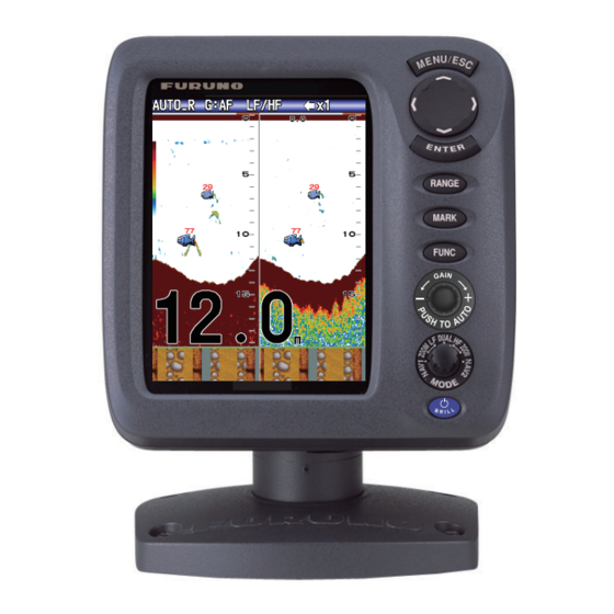
LCD, 8.4 property of the LCD. inch (FCV-587) or 5.7-inch (FCV-627). The main features of the FCV-627/587 are • Bright color LCD gives excellent readability even in broad daylight. • Waterproof construction permits installa- tion on open bridge. -
Page 7: System Configuration
SYSTEM CONFIGURATION Solid lines, standard equipment; dashed lines, optional equipment, and dot-dash lines, local sup- ply. For wiring, see the interconnection diagram at the back of this manual. FCV-627 DISPLAY UNIT CV-627-E 12-24 VDC GPS Navigator External Equipment Radio Transmitter*... -
Page 8: Operation
OPERATION Control Description Control Function MENU/ESC • Opens menu. Go back one page in multi-page menu. • Escapes from current operation. • Selects items on the menu. (TrackPad) • Changes settings. • Moves VRM (Variable Range Marker) by using except for nav mode. -
Page 9: Power On/Off
1. OPERATION Power On/Off Display Mode 1. Rotate the MODE knob to open the mode 1. Press the /BRILL key to turn on the setting window, which is displayed for six power. The unit beeps then the startup seconds. screen appears. Nav data mode 1 3-5 seconds later Low frequency zoom mode*... -
Page 10: Dual Frequency Display
1. OPERATION 1.4.3 Zoom displays Picture advance Zoom mode expands chosen area of the sin- speed Gain gle frequency picture. Three modes are avail- Alarm Display able: bottom lock, bottom zoom and marker icon Range mode zoom. The default zoom mode is bottom lock. AUTO_R G:AF AUTO_R G:AF x1 x1... -
Page 11: Nav Data Display
1. OPERATION 1.4.4 Nav data display Bottom zoom display The bottom zoom mode expands bottom and The nav data displays appear on the left 2/3 bottom fish on the left-half window. This mode of the screen. Data other than depth requires is useful for tracking bottom contour. -
Page 12: How To Select A Range
1. OPERATION How to Select a 3. For [Manual], use the RANGE key (or ) to select the range. Range Basic Range Unit The basic range may be selected in the [Auto] or [Manual] mode. 1000 Note: The RANGE key is inoperative when the bottom discrimination feature is active. -
Page 13: How To Measure Depth
1. OPERATION How to Measure Depth The VRM (Variable Range Marker) functions to measure the depth to schools of fish, etc. This function is inoperative when a NAV data display is active. Too high Correct Too low 1. Press the GAIN knob to open the [Auto 1. -
Page 14: Menu Operating Procedure
1. OPERATION Menu Operating 6. Press the ENTER key (or ) to save the setting. The setting box or window disap- Procedure pears. To escape without changing a set- ting, press the MENU/ESC key instead of Your fish finder has five main menus: Sound- the ENTER key. -
Page 15: Picture Advance Speed
1. OPERATION 2. Select [Shift] and press the ENTER key. Fast Slow 1. Open the menu, select [Sounder] and 3. Set the amount of shift desired and press press the ENTER key. the ENTER key. The step for the amount 2. -
Page 16: How To Reduce Interference
1. OPERATION 1.11 How to Reduce 1.12 How to Reduce Interference Low Level Noise Interference from other acoustic equipment Low intensity "speckles," caused by sedi- operating nearby or other electronic equip- ments in the water or noise, may appear over ment on your boat may show itself on the dis- most of screen. -
Page 17: How To Erase Weak Echoes
1. OPERATION 1.13 How to Erase 1.14 A-scope Display Weak Echoes The A-scope display shows echoes at each transmission with amplitudes and tone pro- Sediment in the water or reflections from portional to their intensities, on the right 1/3 of plankton may be painted on the display in low the screen. -
Page 18: Fish Information (Accu-Fish Tm )
1. OPERATION 1.15 Fish Information 4. Press the MENU/ESC key twice to close the window. (ACCU-FISH x1 x1 AUTO_R G:AF AUTO_R G:AF The ACCU-FISH feature measures the length of individual fish and tags the fish with a fish symbol whose size is proportional to the Weak reflection (small school of length of the fish. -
Page 19: How To Activate Accu-Fish Tm
1. OPERATION • The TX pulse length changes according to 4. Select desired symbol and press the EN- TER key. The size of the symbol is scaled ACCU-FISH On/Off state. This causes a according to the estimated length of the difference in both sensitivity and the ech- fish. -
Page 20: Bottom Discrimination Display
1. OPERATION 1.16 Bottom Discrimi- About the bottom discrimination display nation Display • The bottom discrimination display provides an estimate of bottom composition. Actual The bottom discrimination display analyzes composition may be different. the bottom echo to categorize bottom hard- •... -
Page 21: Alarms
1. OPERATION 2. Select [Bottom Disc.] and press the EN- The bottom type alarm alerts you when the TER key. bottom type (rock, sand, mud, gravel) match- es the bottom type selected. Available when 3. Select [Graphic] or [Probability] and press the bottom discrimination display is active. - Page 22 1. OPERATION 3. Select [Setting] and press the ENTER For [ACCU-FISH] go to step 2). For key. If you want to change the name of an other choices go to step 6). alarm, go to step 4. Otherwise go to step 2) Select [From] (under [Fish Type]) and press the ENTER key.
- Page 23 1. OPERATION Bottom 1) Set [Bottom] to [On] and press the EN- TER key. Starting Alarm range depth 2) Select [From] and (width from starting depth) press the ENTER key. 3) Set the starting depth and press the ENTER key. 4) Select [Span] and Alarm marker press the ENTER key.
-
Page 24: Func Key
1. OPERATION 1.18 FUNC Key Navigation alarms Do the following to set the navigation alarms The FUNC key provides for one-touch call up (speed alarm and arrival alarm). of desired function setting window. 11 items are available: picture advance, shift, interfer- 1. -
Page 25: Waypoints
Tankenmaru feature is active. 1.19.1 How to register a way- point Note 1: When [TLL] or [FURUNO-TLL] is selected at [TLL Output] on the [NMEA] There are two ways to register a waypoint: di- menu of the [System] menu, the latitude... -
Page 26: How To Edit Registered Waypoints
1. OPERATION How to register a waypoint by manual 5. Enter name or latitude and longitude as applicable. entry of latitude and longitude 6. Press the MENU/ESC key to register the 1. Open the menu, select [Data] and press window. the ENTER key. -
Page 27: How To Set Destination Waypoint
1. OPERATION How to erase all waypoints 1. Open the menu, select [Data] and press the ENTER key. 2. Select [Delete All WPT] and press the ENTER key. Two-data Three-data Four-data 3. Select [Yes] and press the ENTER key. display display display Items displayable in (1) - (3): speed (STW)*,... -
Page 28: Menu Description
1. OPERATION 1.21 Menu Description SPEED (SOG) This section describes menu items not previ- ously mentioned. For the [System] menu, see chapter 2. Sounder menu Cross-track error Speed over the ground WIND True(or Apparent) SPEED (STW) STBD Speed thru the water Wind speed and direction COMPASS True(or Mag) - Page 29 1. OPERATION 1. Select [White Marker] in the [Sounder] [Bottom Zone]: Set the area where to display menu and press the ENTER key. the bottom echo when selecting the [Auto] mode on the RANGE key. Note: The bottom discrimination feature must be disabled to use this feature.
-
Page 30: Display Menu
1. OPERATION [TX Rate]: Change pulse repetition rate. Nor- [Temp Graph]: Turn the water temperature mally, the highest rate (10) is used. When in graph on or off. The temperature scale range shallow waters second reflection echoes may is 16°(°F) in [Narrow]; 40°(°F) in [Wide]. Re- appear between the surface and actual bot- quire water temperature data. - Page 31 1. OPERATION [Header Info]: Turn the operational info dis- cations in which case they are displayed alter- play (appears at the top on the screen) on or nately every four seconds (default setting). off. Data Box1 display Data Box2 display AUTO_R G:AF AUTO_R G:AF LF LF...
- Page 32 1. OPERATION [Trip Source]: Select the source for the trip indication: Select [Own] to use the speed data from the speed sensor connected to this unit, or [NMEA] to use speed data from a naviga- tor. [Temp Source]: Select the source for the wa- ter temperature indication: Select [Own] to use the water temperature data from the wa- ter temperature sensor connected to this unit,...
-
Page 33: System Menu
SYSTEM MENU How to Display the Therefore, change the depth unit before changing the preset ranges. System Menu Note: The deepest detection range of Auto The [System] menu mainly consists of items Range is the largest setting of [Range 1] to which do not require regular adjustment. -
Page 34: Units Menu
2. SYSTEM MENU Calib Menu appropriate language and press the ENTER key. Units Menu [Depth]: Select unit of depth measurement, [Draft]: The default depth among [m], [ft], [fm], [HR] (Hiro, Japanese) display shows the distance and [pb]. from the transducer. If you [Temp]: Select unit of water temperature would rather show the dis- measurement, between °C and °F. -
Page 35: Transducer Menu
2. SYSTEM MENU Compensation size Setting value Bottom lock display -50% BL-LF BL-LF x1 x1 AUTO_R G:AF AUTO_R G:AF -65% -75% -80% [Water Type]: Select the water type with which to use the equipment, from [Salt] or [Fresh]. Select correct water type to get accu- rate depth data. -
Page 36: Tankenmaru Menu
2. SYSTEM MENU Tankenmaru Menu • [Demo2], [Demo4]: Deep depth demo mode The Tankenmaru system outputs the video signal from your display unit to the display unit of a Tankenmaru-equipped partner ship, etc., via a radio transmitter. [Output]: Select On to output this unit’s video signal to the display unit of a partner ship in the Tankenmaru system, via a radio transmit- ter. -
Page 37: Maintenance, Troubleshooting
MAINTENANCE, TROUBLE- SHOOTING How to Clean the WARNING Display Unit ELECTRICAL SHOCK HAZARD Dust or dirt may be removed from the cabinet Do not open the equipment with a soft cloth. Water-diluted mild detergent (other than when installing flush may be used if desired. DO NOT use chemi- mount hanger cover). -
Page 38: How To Replace The Fuse
3. MAINTENANCE, TROUBLESHOOTING How to Replace the Troubleshooting Fuse The table below provides basic troubleshoot- ing procedures which the user may follow to The two fuses (Type: FGBO-A 125V 2A PBF, restore normal operation. Code No.: 000-155-849-10) in the power ca- ble assy. -
Page 39: Diagnostics
Program 0252XXX-XX.XX knob’s corresponding on-screen circle "lights" in red if the knob is normal. Re- lease hold and the circle turns white. Item FCV-627 FCV-587 How to check MODE knob: Rotate the Starter 0252388-XX- 0252392-XX- knob. The corresponding on-screen circle "lights"... -
Page 40: Lcd Test
3. MAINTENANCE, TROUBLESHOOTING LCD Test How to Clear the Memory, Reset the This feature tests the LCD for proper display Odometer of colors. Note: To review the seven-tone screen easi- You can restore default menu settings and re- ly, set the brilliance to maximum before start- set the odometer (trip distance indication) as ing the test. -
Page 41: Installation
INSTALLATION Equipment List Standard supply for FCV-627 Name Type Code No. Remarks Display Unit CV-627-E With hard cover Select E: English panel CV-627-C C: Chinese panel Installation CP02-07900 1 set • Cable Assy. (Type: KON-004-02M, Materials Code No.: 000-156-405-12) • Self-tapping Screw (Type: 5×25, Code No.: 000-162-610-10, 4 pcs.) -
Page 42: Display Unit
4. INSTALLATION Optional equipment Name Type Code No. Remarks 520-5PSD* 000-015-204 Thru-hull mount, plastic 520-5MSD* 000-015-212 Thru-hull mount, metal Transducer 520-PLD* 000-177-684-10 Thru-hull mount, plastic 525-5PWD* 000-146-966-01 Transom mount, plastic Triducer (trans- 525T-PWD* 000-177-688-10 Transom mount, plastic ducer with speed/ 525T-BSD* 000-177-685-10 Thru-hull mount, metal... -
Page 43: Thru-Hull Mount Transducer
Bracket cover of the bracket Tape assembly. Cover (FCV-627 only) sponge 2. Fix the bracket assembly to a desktop with four self-tap- ping screws (5×25, supplied). Be sure to follow the recommended main- tenance space show in the outline draw- ing. -
Page 44: 520-5Psd
4. INSTALLATION smoothest. Noise from the propellers also Procedure for installation of the thru-hull adversely affects performance and the mount transducer (for 520-5PSD/520- transducer should not be mounted nearby. 5MSD) The lifting strakes are notorious for creating 1. With the boat hauled out of the water, acoustic noise, and these must be avoided mark the location chosen for mounting by keeping the transducer inboard of them. -
Page 45: Transom Mount Transducer
4. INSTALLATION Transom Mount Flat Washer Transducer Rubber Washer The optional transom mount transducer is Fairing very commonly employed, usually on relative- Block ly small I/O or outboard boats. Do not use this method on an inboard motor boat because turbulence is created by the propeller ahead Hull of the transducer. -
Page 46: How To Mount A Thru-Hull Transducer Inside The Hull
4. INSTALLATION 4. Tape the location shown in the figure be- • Sandpaper (#100) low. Fill the gap between the wedge front • Marine sealant of the transducer and transom with epoxy • Silicone grease material to eliminate any air spaces. Remarks on installation 5x20 •... - Page 47 4. INSTALLATION 2. Decide the most suitable site from the se- 5. Dry the face of the transducer and the lected locations by doing the following: hull. Coat the transducer face and mount- ing location with marine sealant. Harden- 1) Connect the power cable and trans- ing begins in approx.
-
Page 48: Triducer
4. INSTALLATION Triducer Tools and materials needed DO NOT overtighten screws. They may be • Scissors • Masking tape damaged. • Safety goggles • Dust mask 525T-BSD, 526TID-HDD • Electric drill • Screwdrivers For details of the installation, see the manual •... - Page 49 4. INSTALLATION Note 3: For single drive boat, mount on the 4. If you know your transom angle, the starboard side at least 75 mm (3") beyond the bracket is designed for a standard 13° swing radius of the propeller. transom angle.
- Page 50 4. INSTALLATION 2°-10° transom angle (stepped tran- down to provide a projection of 3 mm som and jet boats): Position the shim (1/8"). Tighten the screws. with the tapered end down. 19°-22° transom angle (small alumi- num and fiberglass boats): Position the Cable cover shim with the tapered end up.
- Page 51 4. INSTALLATION Cable routing cal interference, separate the sensor ca- ble from other electrical wiring and "noise" Route the sensor cable over the transom, sources. Coil any excess cable and se- through a drain hole, or thorough a new hole cure it in place with zip-ties to prevent drilled in the transom above the waterline.
-
Page 52: Speed/Temperature Sensor (Option)
4. Apply marine sealant to the flange of the sensor. The height of the coat should be Example: approx. 6 mm FCV-627 5. Pass the sensor casing through the hole. 6. Face the notch on the sensor toward Transducer cable boat's bow and tighten the flange. - Page 53 4. INSTALLATION Cable assy. signal names How to ground the display unit Connector Color Remarks CAUTION TD-A IEC61162-1/ NMEA0183 TD-B Be sure to ground the display unit. RD-A IEC61162-1/ NMEA0183 RD-B An improper ground or no ground can affect 12V-P(+) Power output performance and cause interference to other (12 VDC)
-
Page 54: Iec 61162-1 Data Sentences
4. INSTALLATION Vinyl Sheath Connect to XDR port at rear of display unit Crimp-on Lug FV1.25-3 (LF) MJ-A10SPF Shield Taping Shrink Tubing MJ-A6SRMD MJ-A10SRMD IEC 61162-1 Data Tape connectors with Sentences vulcanizing tape and then vinyl tape to waterproof them. The table below shows the data sentences Bind tape ends with which can be input to and output from your... -
Page 55: Adjustments After Installation
525STID-PWD, skip this procedure. TLL* Target position, output by MARK key. 1. Select [Type] from the [Installation] menu VHW* Speed through the water and press the ENTER key. *Available with connection of applicable sen- sor or navaid. FCV-627 FCV-587... -
Page 56: Ltd/12
4. INSTALLATION 2. Select your transducer and press the EN- NMEA TER key. The NMEA port is disabled when the Tanken- Select [600W] for the 600 W transducer, maru is active. [1kW] for the 1 kW transducer, not listed in the following table. 1. - Page 57 [TLL Output]: Output the position specified by the MARK key to the plotter connected. [Off]: Do not output latitude/longitude. [TLL]: Output latitude/longitude. [FURUNO-TLL]: Output latitude/longitude, depth and water temperature. Requires [FU- RUNO-TLL] enabled device. [Port Monitor]: Port Monitor shows the data sentences input to the [12-24 VDC/NMEA] port.
-
Page 58: Menu Tree
APPENDIX 1 MENU TREE Bold Italic: Default Pic. Advance (x4, x2, x1, 1/2, 1/4, 1/8, 1/16, Stop) MENU key Sounder Zoom Mode (Bottom Lock, Bottom Zoom, Marker Zoom) Shift (0 - 4000 ft, 0 ft) Interference (Auto, High, Medium, Low, Off) Color Erase (0 - 50%, 0%) Clutter (0 - 100%, 0%) White Line (0 - 100%, Edge;... - Page 59 Speed (kn, km/h, mph) Wind (kn, km/h, mph, m/s) Distance (NM, km, SM) NMEA NMEA0183 (Ver 1.5, Ver 2.0, Ver 3.0) NMEA Port (In/Out, In/In) NMEA Output (Off, On) WAAS Setup (Off, WAAS-00 - WAAS-27) TLL Output (Off, TLL, FURUNO-TLL) Port Monitor AP-2...
- Page 60 APPENDIX 1 MENU TREE Calib Draft (-15.0 - +50.0 ft, +0.0 ft) Gain ADJ HF (-20 - +20, +0) Gain ADJ LF (-20 - +20, +0) Temp (-20.0 - +20.0 °F, +0.0 °F) Speed(STW) (-50 - +50 %, +0 %) Fish Size (-80 - +100, +0 %) Water Type (Salt, Fresh) Zero Line...
- Page 61 APPENDIX 2 INSTALLATION FOR TRANSDUCER (THRU-HULL MOUNT) This appendix provides a copy of the installation instructions for AIRMAR transducer. 525T-LTD/12 and 525T-LTD/20 corresponds to B60, SS60-SLTD/12 and SS60-SLTD/20 to SS60. Thru-Hull Record the information found on the cable tag for future reference. Tilted Element Transducer Part No.
-
Page 62: Installation For Transducer (Thru-Hull Mount
APPENDIX 2 INSTALLATION FOR TRANSDUCER (THRU-HULL MOUNT) Mounting Location Identify Your Model CAUTION: Do not mount near water intake or discharge The model name is printed on the cable tag. openings or behind strakes, fittings, or other hull irregularities. Cored Fiberglass Hull Model Hull Outside Hull... - Page 63 APPENDIX 2 INSTALLATION FOR TRANSDUCER (THRU-HULL MOUNT) B60, B75H/M/L, or SS60 P19 housing B150M, B619, SS150M, or SS619 Wrench Wrench Housing flat (2) flat (2) Wrench Housing Housing flat (2) Hull nut Hull nut Hull nut Spacer Washer Washer Washer Hull Hull Hull...
- Page 64 APPENDIX 2 INSTALLATION FOR TRANSDUCER (THRU-HULL MOUNT) 6. Sand and clean the area around the hole, inside and 9-12 mm outside, to ensure that the marine sealant will adhere (3/8-1/2") larger properly to the hull. If there is any petroleum residue inside than the hole Pour in the hull, remove it with either mild household detergent or...
- Page 65 APPENDIX 3 INSTALLATION OF TEM- PERATURE SENSORS © The installation instructions in this chapter are copied from the manufacturer's (AIRMAR Technology Corporation) installation guide, which is included with your sensor. The model numbers mentioned within the documentation should be read as follows: •...
-
Page 66: Installation Of Temperature Sensors
APPENDIX 3 INSTALLATION OF TEMPERATURE SENSORS 9-12 mm (3/8-1/2") pour in larger than the casting hole through the epoxy hull’s outer skin inner skin core hull thickness hull nut hull solid or hollow cylinder outer skin bedding Figure 1. Bedding and installing Figure 2. - Page 67 APPENDIX 3 INSTALLATION OF TEMPERATURE SENSORS Maintenance & Replacement Aquatic growth can accumulate rapidly on the sensor’s surface reducing its performance within weeks. Clean the surface with a Scotch-Brite ® scour pad and mild household detergent taking care to avoid making scratches. If the fouling is severe, lightly wet sand with fine grade wet/dry paper.
-
Page 68: Temperature Sensor
APPENDIX 3 INSTALLATION OF TEMPERATURE SENSORS OWNER’S GUIDE & INSTALLATION INSTRUCTIONS Surface Mount, Analog Record the information found on the cable tag for future reference. Part No._________________Date___________ Temperature Sensor Model T80 Follow the precautions below for optimal product performance and to reduce the risk of property damage, personal injury, and/or death. - Page 69 APPENDIX 3 INSTALLATION OF TEMPERATURE SENSORS Mount the sensor near the centerline and close to the bottom of Cable Routing & Connecting the transom. 1. Route the cable to the instrument, being careful not to tear the cable jacket when passing it through the bulkhead(s) and other Route the sensor cable over the transom, through a drain hole, or parts of the boat.
-
Page 70: Specifications
FURUNO FCV-627/587 SPECIFICATIONS OF FISH FINDER FCV-627/587 GENERAL TX frequency 50 kHz and 200 kHz Transmit method Single or dual frequency transmitting Output power FCV-627 600 W FCV-587 600/1000 W TX rate Max. 3,000 pulse/min Pulse length 0.04 to 3.0 ms Sensitivity 10 dBV... - Page 71 FURUNO FCV-627/587 INTERFACE Data format IEC61162-1 (NMEA0183 Ver 1.5/2.0/3.0) Data sentences Input BWC, GGA, GLL, GNS, HDG, HDT, MDA, MTW, MWV, RMA, RMB, RMC, VHW, VTG, XTE, ZDA Output DBS, DBT, DPT, MTW*, RMB*, VHW*, TLL* by key operation *: External data required...
- Page 77 12/Mar/2015 H.MAKI...
-
Page 79: Index
INDEX LCD test ............33 LF display............2 ACCU-FISH alarm........15 ACCU-FISH setup........ 11 Arrival alarm ..........17 Maintenance..........30 A-scope display...........10 Marker zoom display ........4 MODE knob...........2 Battery............23 Battery voltage alert ........31 Nav data display........4 Bearing source ..........24 Bottom discrimination display......13 Palette ............23 Bottom fish alarm ........15 Picture advance speed........8 Bottom lock display ........3... - Page 80 When a claim is made, FURUNO has a right to choose whether with other electronic devices. The imported product may also be to repair the product or replace it.
- Page 81 24 months from installation date provided the work is done by Furuno U.S.A., Inc. or an AUTHORIZED Furuno dealer during normal shop hours and within a radius of 50 miles of the shop location.
Need help?
Do you have a question about the FCV-627 and is the answer not in the manual?
Questions and answers