
Related Manuals for Keithley 2510


Summary of Contents for Keithley 2510
- Page 1 Models 2510 and 2510-AT ® TEC SourceMeter User’s Manual A G R E A T E R M E A S U R E O F C O N F I D E N C E...
- Page 2 WARRANTY Keithley Instruments, Inc. warrants this product to be free from defects in material and workmanship for a period of 1 year from date of shipment. Keithley Instruments, Inc. warrants the following items for 90 days from the date of shipment: probes, cables, rechargeable batteries, diskettes, and documentation.
- Page 3 Model 2510 and 2510-AT ® TEC SourceMeter User’s Manual All references to the Model 2510 apply to the Model 2510-AT unless otherwise specified. ©2001, Keithley Instruments, Inc. All rights reserved. Cleveland, Ohio, U.S.A. Fifth Printing, February 2002 Document Number: 2510-900-01 Rev. E...
- Page 4 Revision D (Document Number 2510-900-01) ..............June 2001 Revision E (Document Number 2510-900-01) ............February 2002 All Keithley product names are trademarks or registered trademarks of Keithley Instruments, Inc. Other brand names are trademarks or registered trademarks of their respective holders.
- Page 5 Keithley products are designed for use with electrical signals that are rated Installation Category I and Installation Category II, as described in the International Electrotechnical Commission (IEC) Standard IEC 60664. Most measurement, control, and data I/O signals are Installation Category I and must not be directly connected to mains voltage or to voltage sources with high tran- sient over-voltages.
- Page 6 To maintain protection from electric shock and fire, replacement components in mains circuits, including the power transformer, test leads, and input jacks, must be purchased from Keithley Instruments. Standard fuses, with applicable national safety ap- provals, may be used if the rating and type are the same. Other components that are not safety related may be purchased from other suppliers as long as they are equivalent to the original component.
-
Page 7: Table Of Contents
Table of Contents Getting Started General information ..............Warranty information ............Contact information ............Manual addenda ..............Safety symbols and terms ........... Inspection ................Options and accessories ............INPUT/OUTPUT mating connector ......Cables and adapters ............. Rack mount kits ............Carrying case ............... - Page 8 Menus ..................1-19 Main menu ................. 1-19 Rules to navigate menus ............ 1-21 Configuration menus ............1-21 Connections Input/output connections ............Input/output connector ............2-wire connections .............. 4-wire connections ............Reversing TEC connections ..........Sense selection ................OUTPUT sensing ..............INPUT sensing ..............
- Page 9 Proportional (P) control ............Proportional-derivative (PD) control ........Proportional-integral-derivative (PID) control ....PID tuning .................. PID autotune (Model 2510-AT only) ......... Autotune operation .............. Response options ..............Short Lag and Tau time example ......... Long Lag and Tau time example .........
- Page 10 Autotune complete ............4-13 Sensor coefficients ..............4-14 Thermistor coefficients ............4-14 RTD coefficients ..............4-14 Digital I/O Port and Output Enable Digital I/O port ................Port configuration ..............Digital output lines ............Output enable line ............+5V output ..............Digital output configuration ..........
- Page 11 General bus commands ............6-11 REN (remote enable) ............6-11 IFC (interface clear) ............6-11 LLO (local lockout) ............6-11 GTL (go to local) .............. 6-12 DCL (device clear) ............6-12 SDC (selective device clear) ..........6-12 GET (group execute trigger) ..........6-12 SPE, SPD (serial polling) ..........
- Page 12 SPE, SPD (serial polling) ............ Status byte and service request commands ....... 7-10 Programming example — set MSS (B6) when error occurs ......7-10 Status register sets ..............7-11 Register bit descriptions ............ 7-11 Standard event register ..........7-11 Operation event register ..........7-13 Measurement event register ........
- Page 13 10-36 Temperature function ............10-38 Voltage function .............. 10-41 Setpoint tolerance ............10-42 PID autotune (Model 2510-AT only) ......10-43 Select minimum settling time criteria ...... 10-43 Select minimum overshoot criteria ......10-44 Query tau and lag values .......... 10-44 Set temperature start and stop values .......
- Page 14 SYSTem subsystem ..............10-48 Default conditions ............10-48 Select power line frequency setting ......... 10-49 Error queue ..............10-50 Simulate key presses ............10-51 Read version of SCPI standard ........10-52 Reset timestamp .............. 10-52 2-wire/4-wire sense mode ..........10-52 Ground connect mode .............
- Page 15 IEEE-488 and SCPI Conformance Information Introduction ................Example Programs Introduction ................Program requirements ..............Computer hardware requirements ........Software requirements ............General program instructions ..........Basic temperature control program ..........Instrument setup ..............Requested readings ............. Setpoint tolerance temperature sweep ........Overview ................
- Page 16 List of Illustrations Getting Started Figure 1-1 Model 2510 front panel ............Figure 1-2 Model 2510 rear panel ............Figure 1-3 Main menu tree ..............1-22 Connections Figure 2-1 2-wire input/output connections ..........Figure 2-2 4-wire input/output connections ..........Figure 2-3 TEC connections for positive current, cooling operation ..
- Page 17 Status Structure Figure 7-1 Model 2510 status register structure ........Figure 7-2 16-bit status register ............... Figure 7-3 Status byte and service request (SRQ) ........Figure 7-4 Standard event status ............7-12 Figure 7-5 Operation event status ............7-13 Figure 7-6 Measurement event status ............
- Page 18 List of Tables Getting Started Table 1-1 Display examples ..............1-13 Table 1-2 Display messages ..............1-14 Table 1-3 Factory front panel default settings ........1-17 Table 1-4 Main menu ................1-19 Table 1-5 Temperature configuration menu ......... 1-23 Table 1-6 Voltage source configuration menu ........
- Page 19 Table C-4 Typical addressed common command sequence ....C-12 Table C-5 IEEE command groups ............C-13 Table C-6 Model 2510 interface function codes ........C-14 IEEE-488 and SCPI Conformance Information Table D-1 IEEE-488 documentation requirements ........ Table D-2 Coupled commands ...............
-
Page 20: Getting Started
Power-up — Covers line power connection, line voltage settings, fuse replace- ment, and the power-up sequence. • Display — Provides information about the Model 2510 display. • Default settings — Covers factory default setups and saving and recalling user setups. -
Page 21: General Information
General information Warranty information Warranty information is located at the front of this manual. Should your Model 2510 require warranty service, contact the Keithley representative or authorized repair facility in your area for further information. When returning the instrument for repair, be sure to fill out and include the service form at the back of this manual to provide the repair facility with the necessary information. -
Page 22: Inspection
CS-846 connectors can be ordered from Keithley. Cables and adapters Models 7007-1 and 7007-2 shielded GPIB cables — Connect the Model 2510 to the GPIB bus using shielded cables and connectors to reduce electromagnetic interference (EMI). The Model 7007-1 is 1m long; the Model 7007-2 is 2m long. -
Page 23: Rack Mount Kits
Getting Started Models 2510 and 2510-AT User’s Manual Rack mount kits Model 4288-1 single fixed rack mount kit — Mounts a single Model 2510 in a standard 19-inch rack. Model 4288-2 side-by-side rack mount kit — Mounts two instruments (Models 182, 428, 486, 487, 2000, 2001, 2002, 2010, 2015, 2016, 2400, 2410, 2420, 2430, 2510, 6430, 6517, 7001) side-by-side in a standard 19-inch rack. -
Page 24: Front And Rear Panel Familiarization
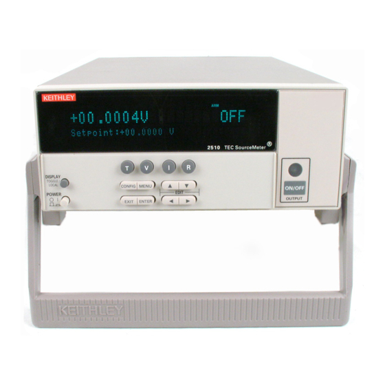
Models 2510 and 2510-AT User’s Manual Getting Started Front and rear panel familiarization Front panel summary The front panel of the Model 2510 is shown in Figure 1-1. The following abbreviated information should be reviewed before operating the instrument. See... - Page 25 Getting Started Models 2510 and 2510-AT User’s Manual Annunciators: EDIT Instrument in edit mode. Questionable reading, invalid cal step. Instrument in GPIB remote mode. TALK Instrument addressed to talk over GPIB. LSTN Instrument addressed to listen over GPIB. Service request over GPIB.
-
Page 26: Rear Panel Summary
Models 2510 and 2510-AT User’s Manual Getting Started Rear panel summary The rear panel of the Model 2510 is shown in Figure 1-2. The following abbreviated infor- mation should be reviewed before operating the instrument. Figure 1-2 Model 2510 rear panel... -
Page 27: Power-Up
Power-up Line power connection The Model 2510 operates from a line voltage in the range of 100 to 240V at a frequency of 50 to 60Hz. Line voltage and line frequency are automatically sensed. Therefore, there are no switches to set. Before connecting the unit to line power, check to be sure the operating voltage in your area is compatible. -
Page 28: System Identification
For example, if the primary address is 15 (factory default), the “IEEE Addr=15” message is displayed. (The Model 2510 does not support a secondary address.) If the RS-232 interface is selected, the “RS-232” message is displayed. -
Page 29: Fuse Replacement
Getting Started Models 2510 and 2510-AT User’s Manual Fuse replacement A rear panel fuse protects the power line input of the Model 2510. If the line fuse needs to be replaced, perform the following steps: WARNING Disconnect the line cord and all test leads and cables from the instru- ment before replacing the line fuse. -
Page 30: Display Readings
Models 2510 and 2510-AT User’s Manual Getting Started 1-11 Display readings Display readings depend on the selected function as discussed below. Temperature function readings The temperature function displays measured and setpoint temperatures. You can use the DISPLAY TOGGLE key to cycle among: •... -
Page 31: Resistance Function Readings
1-12 Getting Started Models 2510 and 2510-AT User’s Manual Resistance function readings The resistance function displays measured RTD and thermistor sensor resistances, as well as setpoint resistances, and you can use the DISPLAY TOGGLE key to cycle among: • Temperature •... -
Page 32: Display Examples
Models 2510 and 2510-AT User’s Manual Getting Started 1-13 Display examples Typical display examples are shown in Table 1-1. Table 1-1 Display examples Function Display toggle sequence* Temperature +025.000°C Setpoint: +025.000°C PEL:-00.072V +025.000°C Setpoint: +025.000°C PEL:-0.0030A +025.000°C Setpoint: +025.000°C PEL:+00.002W +025.000°C... -
Page 33: Display Messages
1-14 Getting Started Models 2510 and 2510-AT User’s Manual Table 1-1 (continued) Display examples Function Display toggle sequence* Resistance +010.00kΩ Setpoint: +010.000kΩ T:+033.200°C +010.00kΩ Setpoint: +010.000kΩ PEL:+01.377V +010.00kΩ Setpoint: +010.000kΩ PEL:+0.3689A +010.00kΩ Setpoint: +010.000kΩ PEL:+00.689W +010.00kΩ Setpoint: +010.000kΩ PEL:+002.75Ω *Use DISPLAY TOGGLE key to cycle through displays for each function. -
Page 34: On/Off Indicator
“Menus,” page 1-19, for more details. Status and error messages During Model 2510 operation and programming, you will encounter a number of front panel messages. Status and error messages are displayed momentarily. See Appendix B for a list of status and error messages and ways to fix common errors. -
Page 35: Default Settings
You can save and restore five of your own user setups as covered below. This feature pro- vides a convenient way to save specific instrument configurations and then recall them as needed. Note that you can also set up the Model 2510 to restore a specific user setup at power-on (see “Power-on configuration,”... -
Page 36: Table 1-3 Factory Front Panel Default Settings
Models 2510 and 2510-AT User’s Manual Getting Started 1-17 Table 1-3 Factory front panel default settings Setting Front panel BENCH and GPIB default* Control function Temperature Temperature function Setpoint 25°C (298.15K, 77°F) Protection high limit 50°C (323.15K, 122°F) Protection low limit 0°C (273.15K, 32°F) - Page 37 1-18 Getting Started Models 2510 and 2510-AT User’s Manual Table 1-3 (continued) Factory front panel default settings Setting Front panel BENCH and GPIB default* Current function Setpoint Current protection limit Proportional constant Integral constant Derivative constant Resistance function Setpoint 100Ω (100Ω RTD or thermistor) 1kΩ...
-
Page 38: Menus
SAVESETUP Configure setup conditions. SAVE Save present Model 2510 setup to memory location. 0 to 4 RESTORE Return the Model 2510 to setup saved in memory. 0 to 4 POWERON Select the power-on default setup. BENCH Powers-on to BENCH defaults. - Page 39 Top level menu choices indicated in bold. Indentation identifies each lower submenu level. When the remote operation interface selection (GPIB or RS-232) is changed, the Model 2510 performs a power-on reset. To check or change options of the selected interface, you must re-enter the menu structure.
-
Page 40: Rules To Navigate Menus
Models 2510 and 2510-AT User’s Manual Getting Started 1-21 Rules to navigate menus Many functions and operations are configured from the front panel menus. Use the follow- ing rules to navigate through these configuration menus: • A menu item is selected by placing the cursor on it and pressing ENTER. Cursor position is denoted by the blinking menu item or option. -
Page 41: Figure 1-3 Main Menu Tree
1-22 Getting Started Models 2510 and 2510-AT User’s Manual Figure 1-3 Main menu tree Press MENU key (Use to select item, then press ENTER). SAVESETUP SAVE RESTORE POWERON BENCH GPIB USER-SETUP-NUMBER RESET COMMUNICATION GPIB RS-232 BAUD BITS PARITY TERMINATOR FLOW-CTRL... -
Page 42: Table 1-5 Temperature Configuration Menu
Models 2510 and 2510-AT User’s Manual Getting Started 1-23 Table 1-5 Temperature configuration menu Configuration menu item Description PROTECTION Configure temperature protection. CONTROL ENABLE or DISABLE temperature protection. LOLIM Program lower temperature limit. HILIM Program higher temperature limit. SENSOR-TYPE Select sensor type and settings. -
Page 43: Table 1-6 Voltage Source Configuration Menu
1-24 Getting Started Models 2510 and 2510-AT User’s Manual Table 1-6 Voltage source configuration menu Configuration menu item Description PROTECTION Set voltage protection limit. Program PID loop constants for voltage control. PROPORTIONAL Set proportional constant. INTEGRAL Set integral constant. DERIVATIVE Set derivative constant. -
Page 44: Table 1-8 Resistance Configuration Menu
Models 2510 and 2510-AT User’s Manual Getting Started 1-25 Table 1-8 Resistance configuration menu Configuration menu item Description FUNCTION Select DC resistance function. AC-OHMS Select AC resistance function. TEMP-CONTROL Program DC resistance parameters. PROTECTION Configure resistance protection. CONTROL ENABLE or DISABLE resistance protection. -
Page 45: Table 1-9 Output Configuration Menu
1-26 Getting Started Models 2510 and 2510-AT User’s Manual Table 1-9 Output configuration menu Configuration menu item Description GND-CONNECT Select input/output analog common (ground) connection. DISABLE Disable ground connection. ENABLE Enable ground connection. ENABLE Enable/disable Digital I/O port output enable line. -
Page 46: Connections
Connections • Input/output connections — Discusses connections for the thermoelectric cooler and temperature sensor. • Sense selection — Summarizes 2-wire and 4-wire sensing selection for both INPUT and OUTPUT terminals. • Ground connect mode — Describes using the ground connect mode. -
Page 47: Input/Output Connections
Use the supplied mating connector for connections (Keithley part number CS-846). NOTE The Model 2510 assumes that a positive output current is a heating current. 2-wire connections Figure 2-1 shows basic 2-wire signal connections. Note that the OUTPUT F (force) termi- nals are connected to the thermoelectric cooler (TEC), while the INPUT F terminals are connected to the temperature sensor. -
Page 48: 4-Wire Connections
Models 2510 and 2510-AT User’s Manual Connections 4-wire connections Figure 2-2 shows basic 4-wire signal connections. In this case, the OUTPUT F (force) and S (Kelvin sense) terminals are connected to the thermoelectric cooler, while the INPUT F and S terminals are connected to the temperature sensor. 4-wire sensor connections are recommended for RTD and thermistor sensors with <1kΩ... -
Page 49: Reversing Tec Connections
Models 2510 and 2510-AT User’s Manual Reversing TEC connections The Model 2510 assumes that a positive TEC current is a heating current. To configure your system so that a positive current is a cooling current, reverse your TEC connections as shown in Figure 2-3. -
Page 50: Sense Selection
(I) is forced through the F+ and F- test leads and the resistance of the thermistor being measured (R ). The Model 2510 then measures the voltage across the thermistor through the same F+ and F- connecting wires and computes the thermistor... -
Page 51: 4-Wire Sensing
Although some small current may flow through the sense wires, it is usually negligible and can generally be ignored for all practical purposes. Since the voltage drop across the sense wires is negligible, the voltage measured by the Model 2510 is essentially ≅ V... -
Page 52: Ground Connect Mode
Models 2510 and 2510-AT User’s Manual Connections Ground connect mode Ground connect connects output low to sensor measurement ground, as shown in Figure 2-5. Without ground connect, the output can float up to ±10V from sensor measure- ment ground. Figure 2-5... -
Page 53: Basic Operation
Operation overview — Summarizes the basic operating characteristics of the Model 2510. • Configuring functions — Provides step-by-step procedures for configuring the Model 2510 temperature, voltage, current, and resistance functions. • Adjusting setpoints — Provides basic information on adjusting setpoints and allowable setpoint ranges. -
Page 54: Safety Precautions
OUTPUT terminals.) Exceeding this value may result in instru- ment damage. Operation overview Control characteristics The Model 2510 has the following basic control characteristics: • Control capabilities — Control thermoelectric cooler (TEC) power to maintain constant temperature, current, voltage, or thermistor resistance. -
Page 55: Limit Characteristics
For each control function (T, V, I, and R), you can program limits to protect the DUT for damage or even to perform limit testing. The Model 2510 will display an appropriate status message if a programmed limit has been exceeded, and you can query if a limit has been... -
Page 56: Table 3-1 Temperature Configuration Menu
Basic Operation Models 2510 and 2510-AT User’s Manual Choose PID, then press ENTER. Program your PROPORTIONAL, INTEGRAL, and DERIVATIVE constants as required. After programming, press EXIT as necessary to return to normal display. Table 3-1 Temperature configuration menu Configuration menu item... -
Page 57: Configuring Voltage
Models 2510 and 2510-AT User’s Manual Basic Operation Configuring voltage Using Table 3-2 as a guide, configure the voltage source as follows: Press CONFIG then V to access the voltage configuration menu. Select PROTECTION, then press ENTER. Using the EDIT keys, set the voltage limit to the desired value, then press ENTER. -
Page 58: Configuring Dc Resistance
Press CONFIG then R to access the resistance configuration menu. Select AC-OHMS, then press ENTER. The output will turn off (if enabled), and the Model 2510 will then display the AC resistance of the TEC whenever the resistance function is enabled by pressing the R function button. -
Page 59: Table 3-4 Resistance Configuration Menu
Models 2510 and 2510-AT User’s Manual Basic Operation Table 3-4 Resistance configuration menu Configuration menu item Description FUNCTION Select DC resistance function. AC-OHMS Select AC resistance function. TEMP-CONTROL Program DC resistance parameters. PROTECTION Configure resistance protection. CONTROL ENABLE or DISABLE resistance protection. -
Page 60: Configuring Output
Basic Operation Models 2510 and 2510-AT User’s Manual Configuring output Using Table 3-5 as a guide, configure the output as follows: Press CONFIG then OUTPUT to enter the output configuration menu. Choose GND-CONNECT, then press ENTER. ENABLE or DISABLE ground connect as required, then press ENTER. -
Page 61: Adjusting Setpoints
Models 2510 and 2510-AT User’s Manual Basic Operation Table 3-6 Setpoint tolerance configuration menu Configuration menu item Description SETPOINT TOLERANCE PERCENTAGE Percent of range for setpoint tolerance (0-100%), default 0.5%. WINDOW-SIZE Number readings to be within tolerance (1-100), default 5. -
Page 62: Basic Front Panel Control-Measure Procedure
Basic front panel control-measure procedure Use the following procedure to perform the basic control-measure operations. NOTE The following procedure assumes that the Model 2510 is already connected to the thermoelectric cooler and temperature sensor as explained in “Input/output connections,” page 2-2. -
Page 63: Step 5: Turn Output On
Section 10 for command details and Appendix E for an example program. NOTE The following procedure assumes that the Model 2510 is already connected to the thermoelectric cooler and temperature sensor as explained in “Input/output connections,” page 2-2. Step 1: Restore defaults. -
Page 64: Step 3: Configure Selected Function
3-12 Basic Operation Models 2510 and 2510-AT User’s Manual Step 3: Configure selected function. Send the commands to program temperature units, protection limits, sensor type, sensor parameters, and PID loop constants. For example, the following commands configure the temperature function:... -
Page 65: Step 8: Turn Output Off
Models 2510 and 2510-AT User’s Manual Basic Operation 3-13 Step 8: Turn output off. When finished, turn the output off and halt PID control by sending: :OUTP OFF Protection limits Protection limits for the four functions are discussed below. Table 3-8 summarizes protec- tion limit characteristics. -
Page 66: Temperature Protection Limits
3-14 Basic Operation Models 2510 and 2510-AT User’s Manual Temperature protection limits The upper and lower temperature limits have a valid range of -50 to +250˚C. If the lower limit is exceeded, “UNDER-TEMP” will be displayed on the front panel, and Bit 1 (UT) of the Measurement Event Register will be set. -
Page 67: Voltage And Current Limit Operating Boundaries
No Operation Setpoint tolerance The setpoint tolerance feature allows you to program the Model 2510 to indicate when the setpoint is within the desired range, or window, for a certain number of readings. For example, with a tolerance of 1%, the setpoint will be within tolerance when the tempera-... -
Page 68: Ranges
3-16 Basic Operation Models 2510 and 2510-AT User’s Manual Ranges Ranges by function are shown in Table 3-9. Table 3-9 Setpoint tolerance ranges Function Range Temperature 275°C 275K 495°F Voltage Current Resistance 200kΩ (100kΩ thermistor) 80kΩ (10kΩ thermistor) 10kΩ (1kΩ thermistor or RTD) 1kΩ... -
Page 69: Setpoint Tolerance Operation
Models 2510 and 2510-AT User’s Manual Basic Operation 3-17 Setpoint tolerance operation Figure 3-2 demonstrates basic setpoint tolerance operation. Operation begins at the Initial Setpoint where the temperature stabilizes at the programmed setpoint. Once the setpoint has been changed (either from the front panel or with a remote command), the temperature gradually increases to the new setpoint as shown. -
Page 70: Temperature Sensors
Available thermistor sensor ranges are 100Ω, 1kΩ, 10kΩ, and 100kΩ. For optimum accu- racy, use the appropriate range for your sensor. The Model 2510 will display URR (Under Resistance Range) or ORR (Over Resistance Range) if the sensor resistance is outside the optimum range. -
Page 71: Pid Control Concepts
• PID tuning — Provides a basic step-by-step procedure for tuning the PID loop for optimum operation. • PID autotune — Details using the Model 2510-AT autotune feature. • Sensor coefficients — Covers thermistor and RTD temperature coefficients. -
Page 72: Temperature Control Model
Temperature control model Figure 4-1 shows the overall control model for the system. The Model 2510 provides cur- rent to the thermoelectric cooler (TEC), which uses the Peltier effect to maintain tempera- ture at the desired setpoint. When current is forced through the TEC in one direction, the device heats;... -
Page 73: On-Off Control
To use the Model 2510 as a P controller, set the derivative and integral constants to zero. Figure 4-2... -
Page 74: Proportional-Derivative (Pd) Control
This form of function is known as proportional-integral-differential, or PID control for which the Model 2510 is optimized. The effect of the integral term is to change the TEC power until the time-averaged value of the temperature error is zero. -
Page 75: Pid Tuning
Time (s) PID tuning It will be necessary for you to tune the Model 2510 PID loop controller by trial and error. The method for tuning the PID loop outlined below is intended only as a starting point, and some experimentation may be required for optimum performance. This procedure is based on the assumption that a critically damped system is optimal, and that stability and noise performance must be traded for response time. -
Page 76: Pid Autotune (Model 2510-At Only)
PID autotune (Model 2510-AT only) The Model 2510-AT autotune algorithm provides the user with a tool to help in tuning the Model 2510-AT Temperature PID loop. It is intended to give a set of PID tuning parame- ters that will give close to the optimum system performance, but it may not result in ideal tuning parameters. - Page 77 Models 2510 and 2510-AT User’s Manual PID Control Concepts Figure 4-4 Response comparison example 1 (short Lag and Tau times) Laser Diode Module with Minimum Settling Time Settled to 1.0% Settled to 0.1% 26.5 (0.030°C) (0.003°C) 26.0 25.5 25.0 24.5 24.0...
-
Page 78: Long Lag And Tau Time Example
PID Control Concepts Models 2510 and 2510-AT User’s Manual Long Lag and Tau time example In order to demonstrate the benefits of response tuning, refer to the example of a system with very long Lag and Tau times (shown in Figure 4-5). -
Page 79: Autotune Limitations
Models 2510 and 2510-AT User’s Manual PID Control Concepts Autotune limitations The Model 2510-AT autotune algorithm assumes that the system response to a step func- tion in the TEC voltage is an exponential temperature rise of the form: system initial (for t <... -
Page 80: Practical Autotune Considerations
4-10 PID Control Concepts Models 2510 and 2510-AT User’s Manual Practical autotune considerations There are several practical considerations to take into account when using autotune. Each of these is outlined below. TEC module gain The gain of a TEC module varies with operating temperature and increases with increas- ing temperature. -
Page 81: Using Autotune Commands
Using autotune commands Autotune command summary Table 4-3 summarizes Model 2510-AT autotune commands. Note that all of these com- mands are part of the :SOURce[1]:TEMPerature subsystem, which is fully described in the Section 10 of the Model 2510 User’s Manual. -
Page 82: Basic Autotune Procedure
4-12 PID Control Concepts Models 2510 and 2510-AT User’s Manual Table 4-3 (cont.) Autotune commands Command Description :STOP? Query stop temperature value. :INITiate Initiate autotune procedure. :SYSTAU Program rate for SHOR, MED, or LONG Tau loads. :SYSTAU? Query Systau value. -
Page 83: Autotune Complete
Autotune complete Your can program the Model 2510-AT to generate an SRQ when the autotune process is complete by setting bit 7 in both the Operation Event Enable and Service Request Enable registers. See Section 7 for details. -
Page 84: Sensor Coefficients
4-14 PID Control Concepts Models 2510 and 2510-AT User’s Manual Sensor coefficients Thermistor coefficients The thermistor sensor coefficients A, B, and C linearize the thermistor temperature- resistance curve and are related using the Steinhart and Hart equation as follows: B 1nR... -
Page 85: Digital I/O Port And Output Enable
Digital I/O Port and Output Enable • Digital I/O port — Details Digital I/O port configuration, connections, and setting I/O port operating parameters. • Output enable line — Discusses output enable line operation, and describes how to activate the line. -
Page 86: Digital I/O Port
Digital I/O Port and Output Enable Models 2510 and 2510-AT User’s Manual Digital I/O port The Model 2510 has a digital input/output port that can be used to control external digital circuitry and for a test fixture output enable circuit. Port configuration... -
Page 87: Output Enable Line
Models 2510 and 2510-AT User’s Manual Digital I/O Port and Output Enable Output enable line The output enable line is intended for use with a test fixture to disable the output when the protection lid is open. See “Output enable line,” page 5-6, for details. -
Page 88: Source Operation
Digital I/O Port and Output Enable Models 2510 and 2510-AT User’s Manual Source operation Figure 5-3 shows the basic output configuration for source operation. In this case, the external relay coil is connected between the digital output line (pins 1 to 4) and ground (pin 9). -
Page 89: Table 5-1 Digital Output Line Settings
Models 2510 and 2510-AT User’s Manual Digital I/O Port and Output Enable Table 5-1 Digital output line settings Decimal OUT 4 OUT 3 OUT 2 OUT 1 value* L = Low (Gnd) H = High (>+3V) *Via remote, send :SOUR2:TTL<Decimal_value>. See :SOURce2 subsystem in... -
Page 90: Output Enable Line
fixture is opened. Overview When the output enable line is active (see below), the output of the Model 2510 cannot be turned on unless the enable line is pulled low through a switch to ground as shown in Figure 5-4A. -
Page 91: Figure 5-4 Using Output Enable
(pin 5 or 9) A. 2510 OUTPUT can be turned on. Model 2510 Test Fixture Enable (pin 8) Enable- Fixture Switch Digital I/O (Lid Open) (pin 5 or 9) B. 2510 OUTPUT turns off and cannot be re-enabled until closed again. -
Page 92: Remote Operations
GPIB operation — Covers GPIB bus standards, bus connections, and primary address selection. • RS-232 interface operation — Outlines use of the RS-232 interface to control the Model 2510 via remote. • Front panel GPIB operation — Summarizes GPIB error messages, status indica- tors, and using the LOCAL key. -
Page 93: Differences: Remote Vs. Local Operation
The GPIB bus is the IEEE-488 interface. You must select a unique address for the Model 2510. The address is displayed when the instrument is turned on, and you can use the MENU/COMMUNICATION/GPIB selection to view the address after the unit is... -
Page 94: Gpib Operation
The above standards define a syntax for sending data to and from instruments, how an instrument interprets this data, what registers should exist to record the state of the instru- ment, and a group of common commands. The Model 2510 also conforms to this standard: •... -
Page 95: Gpib Connections
Remote Operations Models 2510 and 2510-AT User’s Manual GPIB connections To connect the Model 2510 to the GPIB bus, use a cable equipped with standard IEEE-488 connectors as shown in Figure 6-1. Figure 6-1 IEEE-488 connector To allow many parallel connections to one instrument, stack the connectors. Two screws are located on each connector to ensure that connections remain secure. - Page 96 IEEE-488 cables. Available shielded cables from Keithley are Models 7007-1 and 7007-2. To connect the Model 2510 to the IEEE-488 bus, follow these steps: Line up the cable connector with the connector located on the rear panel. The con- nector is designed so it will fit only one way.
-
Page 97: Primary Address
Models 2510 and 2510-AT User’s Manual Primary address The Model 2510 ships from the factory with a GPIB primary address of 15. When the unit powers up, it momentarily displays the primary address. You can set the address to a value from 0 to 30, but do not assign the same address to another device or to a controller that is on the same GPIB bus (controller addresses are usually 0 or 21). -
Page 98: Data Bits And Parity
No parity is only valid when using 8 data bits. Terminator The Model 2510 can be configured to terminate each program message that it transmits to the controller with any of the following combinations of <CR> and <LF>: <CR>... -
Page 99: Rs-232 Connections
DB-25 connector on one end and a DB-9 connector on the other, wired straight through (not null modem). NOTE To minimize interference caused by electromagnetic radiation, use only shielded RS-232 cables such as the Keithley Model 7009-5. Figure 6-4 RS-232 interface connector RS-232... -
Page 100: Front Panel Gpib Operation
Models 2510 and 2510-AT User’s Manual Remote Operations Table 6-2 provides pinout identification for the 9-pin (DB-9) or 25-pin (DB-25) serial port connector on the computer (PC). Table 6-2 PC serial port pinout Signal DB-9 pin number DB-25 pin number... -
Page 101: Talk
Clear) command. LSTN This indicator is on when the Model 2510 is in the listener active state, which is activated by addressing the instrument to listen with the correct MLA (My Listen Address) com- mand. LSTN is off when the unit is in the listener idle state. Place the unit in the listener idle state by sending UNL (Unlisten), addressing it to talk, or sending IFC (Interface Clear) command over the bus. -
Page 102: General Bus Commands
IFC (interface clear) The IFC command is sent by the controller to place the Model 2510 in the local, talker, lis- tener idle states. The unit responds to the IFC command by cancelling front panel TALK or LSTN lights, if the instrument was previously placed in one of these states. -
Page 103: Gtl (Go To Local)
GET is a GPIB trigger that is used as an arm event to control operation. SPE, SPD (serial polling) Use the serial polling sequence to obtain the Model 2510 serial poll byte. The serial poll byte contains important information about internal functions. (See... -
Page 104: Commands And Command Parameters
Models 2510 and 2510-AT User’s Manual Remote Operations 6-13 Commands and command parameters Common commands and SCPI commands may or may not use a parameter. The following are some examples: *SAV <NRf> Parameter (NRf) required *RST No parameter used :SOURce:CURRent:LCONstants <n>... -
Page 105: Query Commands
6-14 Remote Operations Models 2510 and 2510-AT User’s Manual <numlist> Numlist — Specify one or more numbers for a list. Example: :STATus:QUEue:ENABle (-110:-222) Enable errors -110 through -222 <NDN> Non-decimal numeric — This parameter is used to send values in the binary, octal, or hexadecimal format. -
Page 106: Leading Colon
Models 2510 and 2510-AT User’s Manual Remote Operations 6-15 Leading colon The leading colon is not necessary, and not using the leading colon will slightly increase response times. Example: :FORM:ELEM = FORM:ELEM NOTE The “*” for common commands is always required. -
Page 107: Program Messages
6-16 Remote Operations Models 2510 and 2510-AT User’s Manual Program messages A program message is made up of one or more command words sent by the computer to the instrument. Each common command is a three letter acronym preceded by an asterisk (*). -
Page 108: Command Path Rules
Models 2510 and 2510-AT User’s Manual Remote Operations 6-17 After the first command (:enab) is executed, the path pointer is at the third command level in the structure. Since :enab? is also on the third level, it can be typed in without repeating the entire path name. -
Page 109: Response Messages
6-16), the multiple response messages for all the queries are sent to the computer when the Model 2510 is addressed to talk. The responses are sent in the order the query commands were sent and are separated by semicolons (;). Items within the same query are separated by commas (,). -
Page 110: Status Structure
Status Structure • Overview — Provides an operational overview of the status structure for the Model 2510. • Clearing registers and queues — Covers the actions that clear (reset) registers and queues. • Programming and reading registers — Explains how to program enable registers and read any register in the status structure. -
Page 111: Overview
Status Structure Models 2510 and 2510-AT User’s Manual Overview The Model 2510 provides a series of status registers and queues allowing the operator to monitor and manipulate the various instrument events. The status structure is shown in Figure 7-1. The heart of the status structure is the Status Byte Register. This register can be read by the user’s test program to determine if a service request (SRQ) has occurred, and... - Page 112 Models 2510 and 2510-AT User’s Manual Status Structure Figure 7-1 Model 2510 status register structure Questionable Event Questionable Questionable Condition Event Enable Register Register Register & & & & & & & Logical & Calibration Summary & & & &...
-
Page 113: Clearing Registers And Queues
Models 2510 and 2510-AT User’s Manual Clearing registers and queues When the Model 2510 is turned on, the bits of all registers in the status structure are cleared (reset to 0), and the two queues are empty. Commands to reset the event and event... -
Page 114: Programming And Reading Registers
Models 2510 and 2510-AT User’s Manual Status Structure Programming and reading registers Programming enable registers The only registers that can be programmed by the user are the enable registers. All other registers in the status structure are read-only registers. The following explains how to ascertain the parameter values for the various commands used to program enable registers. -
Page 115: Reading Registers
Status Structure Models 2510 and 2510-AT User’s Manual The <NDN> (non-decimal numeric) parameter type is used to send non-decimal values. These values require a header (#B, #H or #Q) to identify the data format being sent. The letter in the header can be upper or lower case. The <NRf> (numeric representation for- mat) parameter type is used to send decimal values, and does not use a header. -
Page 116: Status Byte And Service Request (Srq)
Models 2510 and 2510-AT User’s Manual Status Structure Status byte and service request (SRQ) Service request is controlled by two 8-bit registers; the Status Byte Register and the Ser- vice Request Enable Register. Figure 7-3 shows the structure of these registers. -
Page 117: Status Byte Register
Service (RQS) bit or the Master Summary Status (MSS) bit: • When using the serial poll sequence of the Model 2510 to obtain the status byte (a.k.a. serial poll byte), B6 is the RQS bit. See “Serial polling and SRQ,” page 7-9, for details on using the serial poll sequence. -
Page 118: Service Request Enable Register
Typically, SRQs are managed by the serial poll sequence of the Model 2510. If an SRQ does not occur, bit B6 (RQS) of the Status Byte Register will remain cleared, and the pro- gram will simply proceed normally after the serial poll is performed. -
Page 119: Programming Example - Set Mss (B6) When Error Occurs
7-10 Status Structure Models 2510 and 2510-AT User’s Manual Status byte and service request commands The commands to program and read the Status Byte Register and Service Request Enable Register are listed in Table 7-3. For details on programming and reading registers, see “Programming enable registers,”... -
Page 120: Status Register Sets
Bit B6, User Request (URQ) — Set bit indicates that the LOCAL key on the Model 2510 front panel was pressed. • Bit B7, Power ON (PON) — Set bit indicates that the Model 2510 has been turned off and turned back on since the last time this register has been read. -
Page 121: Figure 7-4 Standard Event Status
7-12 Status Structure Models 2510 and 2510-AT User’s Manual Figure 7-4 Standard event status — — *ESR? Standard Event (B6) (B5) (B4) (B3) (B2) (B1) (B0) (B15 - B8) (B7) Status Register & & & & & & & To Event —... -
Page 122: Operation Event Register
(Model 2510-AT only). Bits B8 and B9 — Not used (always 0). • Bit B10, Idle State (Idle) — Set bit indicates the Model 2510 is in the idle state. • Bits B11 through B14 — Not used. -
Page 123: Measurement Event Register
Bit B7, Reading Overflow (ROF) — Set bit indicates that the reading exceeds the • selected measurement range of the Model 2510. Bits B8 through B10 — Not used. • Bit B11, Output Enable (OE) — Set bit indicates that the Digital I/O port output •... -
Page 124: Measurement Event Status
Models 2510 and 2510-AT User’s Manual Status Structure 7-15 Figure 7-6 Measurement event status — — — — Measurement stat:meas:cond? (B15) (B14) (B13) (B12) (B11) (B10) (B9) (B8) (B7) (B6) (B5) (B4) (B3) (B2) (B1) (B0) Condition Register — —... -
Page 125: Questionable Event Register
7-16 Status Structure Models 2510 and 2510-AT User’s Manual Questionable event register The used bits of the Questionable Event Register (Figure 7-7) are described as follows: • Bits B0 through B7 — Not used. • Bit B8, Calibration Summary (Cal) — Set bit indicates that an invalid calibration constant was detected during the power-up sequence. -
Page 126: Condition Registers
For example, while the Model 2510 is in the idle state, bit B10 (Idle) of the Operation Condition Register will be set. When the instrument is taken out of idle, bit B10 clears. -
Page 127: Event Enable Registers
7-18 Status Structure Models 2510 and 2510-AT User’s Manual Event enable registers Figure 7-1 shows, each status register set has an enable register. Each event register bit is logically ANDed (&) to a corresponding enable bit of an enable register. Therefore,... -
Page 128: Programming Example - Program And Read Register Set
Output Queue is considered cleared when it is empty. An empty Output Queue clears the MAV bit in the Status Byte Register. A message is read from the Output Queue by addressing the Model 2510 to talk after the appropriate query is sent. -
Page 129: Error Queue
Error Queue is empty. When empty, the message “0, No Error” is placed in the queue. Messages in the Error Queue are preceded by a code number. Negative (-) numbers are used for SCPI-defined messages, and positive (+) numbers are used for Keithley-defined messages. As shown in... -
Page 130: Programming Example - Read Error Queue
Models 2510 and 2510-AT User’s Manual Status Structure 7-21 Table 7-9 Error queue commands Command Description Default STATus STATus Subsystem: :QUEue Read Error Queue: (Note 1) [:NEXT]? Read and clear oldest error/status (code and message). :ENABle <list> Specify error and status messages for Error Queue. -
Page 131: Common Commands
Common Commands • Command summary — Lists the IEEE-488.2 common commands used by the Model 2510. • Command reference — Provides a detailed reference for all common commands except for those associated with the status structure, which are discussed in... -
Page 132: Command Summary
Returns summary of installed options. *RCL <NRf> Recall command Returns the Model 2510 to the user-saved setup. *RST Reset command Returns the Model 2510 to the *RST default condi tions. *SAV <NRf> Save command Saves the present setup as the user-saved setup. *SRE <NRf>... -
Page 133: Command Reference
Reads identification code The identification code includes the manufacturer, model number, serial number, and firm- ware revision levels and is sent in the following format: KEITHLEY INSTRUMENTS INC., MODEL 2510, xxxxxxx, yyyyy/zzzzz /b Where: 2510 is the model number. xxxxxxx is the serial number. -
Page 134: Sav
Cancels response to any previously received *OPC and *OPC? commands. *TRG — trigger Send bus trigger to Model 2510 Use the *TRG command to issue a GPIB trigger to the Model 2510. It has the same effect as a group execute trigger (GET). *TST? — self-test query Run self test and read result Use this query command to perform a checksum test on ROM.- Save -
Page 135: Wai - Wait-To-Continue
Models 2510 and 2510-AT User’s Manual Common Commands *WAI — wait-to-continue Wait until previous commands are completed Effectively, the *WAI command is a No-Op (no operation) for the Model 2510 and thus, does not need to be used. Two types of device commands exist: •... -
Page 136: Scpi Signal-Oriented Measurement Commands
SCPI Signal-Oriented Measurement Commands • Command summary — Summarizes those commands used to configure and acquire readings. • Acquiring readings — Describes commands to acquire post-processed readings, both trigger and acquire readings, and to perform a single measurement. • Command examples — Gives several examples using signal-oriented commands. -
Page 137: Command Summary
This query command requests the latest post-processed readings stored in the sample buffer. After sending this command and addressing the Model 2510 to talk, the readings are sent to the computer. This com- mand does not affect the instrument setup. -
Page 138: Measure[:
The :INITiate command starts operation by taking the instrument out of idle. After all control-measure operations are completed, the Model 2510 goes back into idle at which time the :FETCh? command is exe- cuted. The readings are sent to the computer and displayed when the unit is addressed to talk.] -
Page 139: Read
The :INITiate command starts operation by taking the instrument out of idle. After all control-measure operations are completed, the Model 2510 goes back into idle at which time the :FETCh? command is exe- cuted. The readings are sent to the computer and displayed when the unit is addressed to talk. -
Page 140: Scpi Command Reference
SCPI Command Reference • Reference tables — Summarizes each SCPI command subsystem. • SCPI subsystems — Provides detailed information on all commands in each SCPI subsystem. -
Page 141: Reference Tables
10-2 SCPI Command Reference Models 2510 and 2510-AT User’s Manual Reference tables The SCPI commands that control the Model 2510 are summarized in the table below, which lists the various subsystems and reference tables. Reference Subsystem Description table :DISPlay Control/read front panel display attributes. -
Page 142: Table 10-1 :Display Subsystem Commands
Models 2510 and 2510-AT User’s Manual SCPI Command Reference 10-3 Table 10-1 :DISPlay subsystem commands Default Command Description parameter SCPI :DISPlay [:WINDow[1]] :ATTRibutes? Returns a 20 character string representing the attributes of the characters on the top line. Blink- ing characters are 1 and others are 0. -
Page 143: Table 10-2 :Format Subsystem Commands
10-4 SCPI Command Reference Models 2510 and 2510-AT User’s Manual Table 10-2 :FORMat subsystem commands Default Command Description parameter SCPI :FORMat :BORDer <name> Specify byte order when transferring binary Note data. <name> =NORMal | SWAPped :BORDer? Query byte order. [:DATA] <type>[,<length>] Specify data format used when transferring ASCii numeric data. -
Page 144: Table 10-4 :Sense[1] Subsystem Commands
Models 2510 and 2510-AT User’s Manual SCPI Command Reference 10-5 Table 10-4 :SENSe[1] subsystem commands Command Description Default parameter SCPI [:SENSe[1]] :CURRent[:DC] Path to configure DC current. :PROTection Set current protection. [:LEVel] <n> Set protection current level. <n> = 1.0 to 5.25 (A) | MIN | MAX | DEF. - Page 145 10-6 SCPI Command Reference Models 2510 and 2510-AT User’s Manual Table 10-4 (continued) :SENSe[1] subsystem commands Command Description Default parameter SCPI [:SENSe[1]] :TEMPerature :RTD :RANGe <n> Set RTD resistance range. <n> = 0 to 1000 (100,1000) | MIN | MAX | DEF :RANGe? Query RTD resistance range.
-
Page 146: Table 10-5 :Source[1] Subsystem Commands
Models 2510 and 2510-AT User’s Manual SCPI Command Reference 10-7 Table 10-5 :SOURce[1] subsystem commands Command Description Default parameter SCPI :SOURce[1] Path to SOURce[1] commands. :CLEar [:IMMediate] Clear source immediately. :CURRent Program current source. :LCONstants Program current PID loop constants. - Page 147 10-8 SCPI Command Reference Models 2510 and 2510-AT User’s Manual Table 10-5 (continued) :SOURce[1] subsystem commands Command Description Default parameter SCPI :SOURce[1] :RESistance [:LEVel] [:IMMediate] [:AMPLitude] <n> Set resistance level. <n> =1 to 1.000e3 (Ω) 100 (100Ω RTD for 100Ω thermistor, 1 to 250 (Ω) or ther), for 100Ω...
- Page 148 Models 2510 and 2510-AT User’s Manual SCPI Command Reference 10-9 Table 10-5 (continued) :SOURce[1] subsystem commands Command Description Default parameter SCPI :SOURce[1] :TEMPerature Temperature commands. :ATUNe Auto Tune commands (Model 2510-AT only). :LCONstants Temperature PID loop constants. :MSETtle Use minimum settling time criteria.
- Page 149 10-10 SCPI Command Reference Models 2510 and 2510-AT User’s Manual Table 10-5 (continued) :SOURce[1] subsystem commands Command Description Default parameter SCPI :SOURce[1] :TEMPerature :PROTection Set temperature protection. [:HIGH] Upper temperature limit. [:LEVel] <n> Set upper temperature limit. 50.0°C, <n> = -50 to +250°C, 223.15 to 523.15K, 323.15K,...
-
Page 150: Table 10-6 :Source2 Subsystem Commands
Models 2510 and 2510-AT User’s Manual SCPI Command Reference 10-11 Table 10-5 (continued) :SOURce[1] subsystem commands Command Description Default parameter SCPI :SOURce[1] :STOLerance Program setpoint tolerance parameters. [:PERCent] <n> Percentage of range. <n> = 0.00-100.00 (%) | MIN | MAX | DEF [:PERCent]? Query percent of range value. -
Page 151: Table 10-7 :Status Subsystem Commands
10-12 SCPI Command Reference Models 2510 and 2510-AT User’s Manual Table 10-7 :STATus subsystem commands Default Command Description parameter SCPI :STATus Note 1 :MEASurement Path to control measurement event registers. [:EVENt]? Read the event register. Note 2 :ENABle <NRf> | <NDN>... -
Page 152: Table 10-8 :System Subsystem Commands
Models 2510 and 2510-AT User’s Manual SCPI Command Reference 10-13 Table 10-8 :SYSTem subsystem commands Default Command Description parameter SCPI :SYSTem Path to SYSTem subsystem. :KEY <n> Simulate key press. :KEY? Query the last pressed key. :PRESet Return to :SYST:PRES (BENCH) defaults. -
Page 153: Display Subsystem
Query temperature units. DISPlay subsystem The DISPlay subsystem is used to control the Model 2510 front panel two-line display via remote. The top, larger display has 20 characters, while the bottom, smaller display has 32 characters. Commands are summarized in Table 10-1. -
Page 154: Read Display
These query commands are used to read what is currently being dis- played on the top and bottom displays. After sending one of these com- mands and addressing the Model 2510 to talk, the displayed data (message or reading) will be sent to the computer. - Page 155 10-16 SCPI Command Reference Models 2510 and 2510-AT User’s Manual :STATe <b> :DISPlay[:WINDow[1]]:TEXT:STATe <b> Control message; top display :DISPlay:WINDow2:TEXT:STATe <b> Control message; bottom display Parameters <b> = 0 or OFF Disable text message for specified display 1 or ON Enable text message for specified...
-
Page 156: Ascii Display Values
Models 2510 and 2510-AT User’s Manual SCPI Command Reference 10-17 ASCII display values DISPLAY DISPLAY DISPLAY invalid ` (open quote) invalid invalid invalid invalid invalid invalid invalid invalid invalid invalid invalid invalid < invalid invalid > invalid µ ± ×... - Page 157 10-18 SCPI Command Reference Models 2510 and 2510-AT User’s Manual ≥ selftest3 ÿ ≠ selftest4 lightning ≡ selftest5 ≈ selftest6 box3 ∞ selftest7 box4 selftest8 » box5 selftest9 « box6 selftest10 ¿ box7 selftest11 ¡ box8 selftest12 ¢ box9 selftest13 £...
-
Page 158: Format Subsystem
MEASure[:<function>]?, over the GPIB. All other queries are returned in the ASCII format. NOTE Regardless of which data format for output strings is selected, the Model 2510 will only respond to input commands using the ASCII format. ASCII format The ASCII data format is in a direct readable form for the operator. -
Page 159: Figure 10-2 Ieee-754 Single Precision Data Format (32 Data Bits)
Header, Byte 4, Byte 3, Byte 2, Byte 1. The header and terminator are sent only once for each READ? During binary transfers, never un-talk the Model 2510 until after the data is read (input) to the computer. Also, to avoid erratic operation, the readings of the data string (and terminator) should be acquired in one piece. -
Page 160: Data Elements
STATus word associated with it. This STATus word is accessible via the :FORMat:ELEMents STATus element. Internally, the Model 2510 maintains this STATus element as a 16-bit integer. Each bit within this integer provides status information about a particular process asso- ciated with the construction of the measurement. - Page 161 10-22 SCPI Command Reference Models 2510 and 2510-AT User’s Manual Name Description VOLTAGE_OFLO This bit is set to 1 when the voltage measurement was made in an over-range condition. Cleared to 0 otherwise. CURRENT_OFLO This bit is set to 1 when the current measurement was made in an over-range condition.
-
Page 162: Byte Order
Models 2510 and 2510-AT User’s Manual SCPI Command Reference 10-23 Byte order :BORDer <name> :FORMat:BORDer <name> Specify binary byte order Parameters <name> = NORMal Normal byte order for binary formats SWAPped Reverse byte order for binary formats Query :BORDer? Query byte order... -
Page 163: Status Register Format
10-24 SCPI Command Reference Models 2510 and 2510-AT User’s Manual Status register format :SREGister <name> :FORMat:SREGister <name> Set data format for reading status registers Parameters <name> = ASCii Decimal format HEXadecimal Hexadecimal format OCTal Octal format BINary Binary format Query... -
Page 164: Output Subsystem
This command is used to turn the source output on or off. Control or measurements cannot be performed while the source is off. Turning the source off places the Model 2510 in the idle state. Output enable line control :STATe <b>... -
Page 165: Sense1 Subsystem
Models 2510 and 2510-AT User’s Manual SENSe1 subsystem The SENSe1 subsystem is used to configure and control the measurement functions of the Model 2510. Measurement functions include current, temperature, and resistance. The commands for this subsystem are summarized in Table 10-4. -
Page 166: Resistance Function
Models 2510 and 2510-AT User’s Manual SCPI Command Reference 10-27 Resistance function :CURRent <n> [:SENSe[1]]:RESistance:CURRent <n> Set RTD or thermistor sensor current Parameters <n> = 3e-6 to 2.5e-3 Set sensor current (3.3e-6, 1e-5, 3.33e-5, 1e-4, 8.333e-4, 2.5e-3) MINimum 3e-6 MAXimum 2.5e-3... -
Page 167: Temperature Function
10-28 SCPI Command Reference Models 2510 and 2510-AT User’s Manual :RANGe <n> [:SENSe[1]]:RESistance:RTD:RANGe <n> Set RTD resistance range Parameters <n> = 0 to 1000 Set RTD resistance range (100 or 1000) MINimum MAXimum 1000 DEFault Query :RANGe? Query sensor resistance range This command programs the temperature sensor resistance range. -
Page 168: Rtd Sensor Parameters
Models 2510 and 2510-AT User’s Manual SCPI Command Reference 10-29 :AUTO <b> [:SENSe[1]]:TEMPerature:CURRent:AUTO <b> Enable/disable auto sensor current Parameters <b> = 1 or ON Enable auto sensor current 0 or OFF Disable auto sensor current Query :AUTO? Query auto sensor current state Description This command enables or disables the auto sensor current mode. - Page 169 10-30 SCPI Command Reference Models 2510 and 2510-AT User’s Manual :RANGe <n> [:SENSe[1]]:TEMPerature:RTD:RANGe <n> Set RTD resistance range Parameters <n> = 0 to 1000 Set RTD resistance range (100 or 1000) MINimum MAXimum 1000 DEFault Query :RANGe? Query sensor resistance range Description This command programs the temperature sensor resistance range.
-
Page 170: Thermistor Sensor Parameters
Models 2510 and 2510-AT User’s Manual SCPI Command Reference 10-31 :DELTa <n> [:SENSe[1]]:TEMPerature:RTD:DELTa <n> Program RTD sensor delta RTD δ coefficient Parameters <n> = 0 to 5 MINimum MAXimum DEFault 1.507 Query RTD δ coefficient Query :DELTa? This command programs the RTD temperature sensor δ coefficient for Description the USER type RTD sensor. -
Page 171: Solid-State Sensor Parameters
10-32 SCPI Command Reference Models 2510 and 2510-AT User’s Manual :B <n> [:SENSe[1]]:TEMPerature:THERmistor:B <n> Program thermistor sensor B value Parameters <n> = -10 to +10 thermistor B coefficient MINimum MAXimum DEFault 2.33894e-4 Query Query thermistor B coefficient Description This command programs the thermistor temperature sensor B coefficient. - Page 172 Models 2510 and 2510-AT User’s Manual SCPI Command Reference 10-33 :OFFSet <n> [:SENSe[1]]:TEMPerature:VSS:OFFSet <n> Program voltage sensor offset [:SENSe[1]]:TEMPerature:ISS:OFFSet <n> Program current sensor offset Parameters :VSS <n> = -999.999 to 999.999 VSS solid-state sensor offset (K) MINimum -999.999 MAXimum 999.999 DEFault :ISS <n>...
-
Page 173: Source[1] Subsystem
PID controller, and the result of the PID calculation drives the process variable towards the set point. The Model 2510 can be configured as a 50W voltage source capable of delivering ±10V @ ±5A or a 50W current source capable of delivering ±5A @ ±10V. -
Page 174: Current Function
Models 2510 and 2510-AT User’s Manual SCPI Command Reference 10-35 Current function [:AMPLitude] <n> :SOURce[1]:CURRent[:LEVel][:IMMediate][:AMPLitude] <n> Program current amplitude Parameters <n> = -5 to +5A Set current amplitude MINimum MAXimum DEFault Query [:AMPLitude]? Query current amplitude Description This command programs the current amplitude (setpoint) for the current source function. -
Page 175: Resistance Function
10-36 SCPI Command Reference Models 2510 and 2510-AT User’s Manual Resistance function [:AMPLitude] <n> :SOURce[1]:RESistance[:LEVel][:IMMediate][:AMPLitude] <n> Program resistance value Parameters <n> = 1 to 1.000e3Ω 100Ω thermistor 5 to 9.999e3Ω 1kΩ thermistor 50 to 8.000e4Ω 10kΩ thermistor 500 to 2.000e5Ω 100kΩ thermistor 1 to 250Ω... - Page 176 Models 2510 and 2510-AT User’s Manual SCPI Command Reference 10-37 Query [:GAIN]? Query proportional constant :DERivative? Query derivative constant :INTegral? Query integral constant Description These commands program the resistance function PID loop constants, which must be set to appropriate values for suitable control characteris- tics.
-
Page 177: Temperature Function
Query temperature setpoint Description This command programs the temperature setpoint for the temperature function. This value is the temperature at which the Model 2510 will maintain system temperature when the temperature function is enabled. The setpoint cannot exceed the temperature protection limits. - Page 178 Models 2510 and 2510-AT User’s Manual SCPI Command Reference 10-39 :LCONstants :SOURce[1]:TEMPerature:LCONstants[:GAIN] <n> Program proportional constant :SOURce[1]:TEMPerature:LCONstants:DERvative <n> Program derivative constant :SOURce[1]:TEMPerature:LCONstants:INTegral <n> Program integral constant Parameters [:GAIN] <n> = 0 to 1e5 Set proportional constant value MINimum MAXimum DEFault 20.0...
- Page 179 10-40 SCPI Command Reference Models 2510 and 2510-AT User’s Manual :PROTection :SOURce[1]:TEMPerature:PROTection[:HIGH][:LEVel] <n> Program temperature high limit :SOURce[1]:TEMPerature:PROTection[:HIGH]:TRIPped? Query if high limit exceeded :SOURce[1]:TEMPerature:PROTection:LOW[:LEVel] <n> Program temperature low limit :SOURce[1]:TEMPerature:PROTection:LOW:TRIPped? Query if low limit exceeded :SOURce[1]:TEMPerature:PROTection:STATe <b> Enable/disable protection Parameters [:HIGH] <n>...
-
Page 180: Voltage Function
Models 2510 and 2510-AT User’s Manual SCPI Command Reference 10-41 Voltage function [:AMPLitude] <n> :SOURce[1]:VOLTage[:LEVel][:IMMediate][:AMPLitude] <n> Program voltage source value Parameters <n> = -10 to +10V Set voltage source value MINimum MAXimum DEFault Query [:AMPLitude]? Query voltage source value Description This command programs the amplitude (setpoint) for the voltage source. -
Page 181: Setpoint Tolerance
10-42 SCPI Command Reference Models 2510 and 2510-AT User’s Manual :PROTection :SOURce[1]:VOLTage:PROTection[:LEVel] <n> Program voltage limit :SOURce[1]:VOLTage:PROTection:TRIPped? Query if voltage limit exceeded Parameters <n> = 0.5 to +10.5V Set voltage limit value MINimum MAXimum +10.5 DEFault +10.5 Query [:LEVel[? Query voltage limit... -
Page 182: Pid Autotune (Model 2510-At Only)
Models 2510 and 2510-AT User’s Manual SCPI Command Reference 10-43 NOTE Bit 12 of the Measurement Event Register will be set when the setpoint is within the percent tolerance for the programmed number of readings (see below). See Section 7 for status register details. -
Page 183: Select Minimum Overshoot Criteria
Query start temperature :STOP? Query stop temperature Description These commands are used to set the start and stop temperatures for the autotune procedure. The Model 2510-AT will use these values to deter- mine the correct loop constants. Initiate autotune :SOURce[1]:TEMPerature:ATUNe:INITiate Initiate autotune Description This command is used to initiate the autotune process. -
Page 184: Source2 Subsystem
Models 2510 and 2510-AT User’s Manual SCPI Command Reference 10-45 SOURce2 subsystem The SOURce 2 subsystem command is used to set the logic level of the digital output lines, as summarized in Table 10-6. [:LEVel] <NRf> | <NDN> :SOURce2:TTL[:LEVel] <NRf> | <NDN>... -
Page 185: Status Subsystem
10-46 SCPI Command Reference Models 2510 and 2510-AT User’s Manual STATus subsystem The STATus subsystem is used to control the status registers of the Model 2510. The com- mands in this subsystem are summarized in Table 10-7. NOTE These registers and the overall status structure are fully explained in... -
Page 186: Read Condition Registers
Models 2510 and 2510-AT User’s Manual SCPI Command Reference 10-47 Read condition registers :CONDition? :STATus:MEASurement:CONDition? Read Measurement Condition :STATus:QUEStionable:CONDition? Read Questionable Register :STATus:OPERation:CONDition? Read Operation Condition Description These query commands are used to read the contents of the condition registers. -
Page 187: System Subsystem
10-48 SCPI Command Reference Models 2510 and 2510-AT User’s Manual ENABle <list> :STATus:QUEue:ENABle <list> Enable messages for Error Queue Parameters <list> = (numlist) where numlist is a specified list of messages that you wish to enable for the Error (must be in parentheses). -
Page 188: Select Power Line Frequency Setting
Models 2510 and 2510-AT User’s Manual SCPI Command Reference 10-49 :POSetup :SYSTem:POSetup <name> Program power-on defaults Parameters <name> = Power-up to *RST defaults PRESet Power-up to :SYSTem:PRESet defaults SAV0 Power-up to setup stored at memory location 0 SAV1 Power-up to setup stored at memory... -
Page 189: Error Queue
The Error Queue is a first-in, first-out (FIFO) register that can hold up to 10 messages. After sending this command and addressing the Model 2510 to talk, the oldest message is sent to the computer and is then removed from the queue. -
Page 190: Simulate Key Presses
The queue for the :KEY? query command can only hold one key-press. When :KEY? is sent over the bus, and the Model 2510 is addressed to talk, the key-press code number for the last key pressed (either physi- cally or with :KEY) is sent to the computer. -
Page 191: Read Version Of Scpi Standard
Description This action command is used to reset the absolute timestamp to 0 sec- onds. The timestamp also resets to 0 seconds every time the Model 2510 is turned on. Note that time information can be returned with the :READ? and :MEAS? queries by specifying a time element with the :FORMat:ELEMents command (see “FORMat subsystem,”... -
Page 192: Ground Connect Mode
Place the Model 2510 in remote Description This command is used to place the Model 2510 in the remote state. In remote, the front panel keys will be locked out if local lockout is asserted. See :RWLock. :REMote performs the same function as the... -
Page 193: Trigger Subsystem
Table 10-9. NOTE The trigger commands function only in the calibration mode, and they are ignored during normal operation. See the Model 2510 Service Manual for details on calibrating the unit. Initiate control/measure cycle :INITiate :INITiate[:IMMediate] Take Model 2510 out of idle state... -
Page 194: Specifications
Specifications... - Page 195 2510 TEC SourceMeter The Model 2510 Thermoelectric Cooler Controller is designed to: TEC OUTPUT SPECIFICATIONS • control the power to the TEC to maintain a constant temperature, current, voltage, or thermistor resistance OUTPUT RANGE: ±10 VDC at up to ±5 ADC.
- Page 196 Models 2510 and 2510-AT Specifications Accuracy calculations The information below discusses how to calculate accuracy for both TEC measurement and thermal feedback element specifications. Accuracy specifications are stated as follows: Accuracy = ±(% of reading + offset) As an example of how to calculate the actual limits, assume an output voltage of 5V. You can compute the limits from one-year operating voltage accuracy specifications as follows:...
-
Page 197: Status And Error Messages
Status and Error Messages... -
Page 198: Introduction
Each message is preceded by a code number. Negative (-) numbers are used for SCPI- defined messages, and positive (+) numbers are used for Keithley-defined messages. Note that error and status conditions will also set specific bits in various status registers, as sum-... -
Page 199: Table B-1 Status And Error Messages
Models 2510 and 2510-AT User’s Manual Status and Error Messages Table B-1 Status and error messages Number Error message Event Status register -440 Query UNTERMINATED after Standard Event indefinite response -430 Query DEADLOCKED Standard Event -420 Query UNTERMINATED Standard Event... - Page 200 Status and Error Messages Models 2510 and 2510-AT User’s Manual Table B-1 (continued) Status and error messages Number Error message Event Status register -178 Expression data not allowed Standard Event -171 Invalid expression Standard Event -170 Expression error Standard Event...
- Page 201 Models 2510 and 2510-AT User’s Manual Status and Error Messages Table B-1 (continued) Status and error messages Number Error message Event Status register +000 No error Measurement events: +100 Over Temperature Measurement Event +101 Under Temperature Measurement Event +102 Over Voltage...
- Page 202 Status and Error Messages Models 2510 and 2510-AT User’s Manual Table B-1 (continued) Status and error messages Number Error message Event Status register +522 Source - gain data invalid Standard Event +523 Source - offset data invalid Standard Event +524 Source DAC Overflow...
- Page 203 Models 2510 and 2510-AT User’s Manual Status and Error Messages Table B-1 (continued) Status and error messages Number Error message Event Status register +801 Not permitted with OUTPUT on Standard Event +802 OUTPUT blocked by OUTPUT Standard Event Enable +803...
-
Page 204: Eliminating Common Scpi Errors
Status and Error Messages Models 2510 and 2510-AT User’s Manual Eliminating common SCPI errors There are three SCPI errors that occur more often than any others: • -113, “Undefined header” • -410, “Query INTERRUPTED” • -420, “Query UNTERMINATED” The following paragraphs discuss the most common causes for these errors and methods for avoiding them. -
Page 205: 420, "Query Unterminated
Valid query following an invalid command. This situation can occur when you send multiple commands or queries (program message units) within one command string (program message). When the Model 2510 detects an error in a program message unit, it discards all further program message units until the end of the string;... -
Page 206: Ieee-488 Bus Overview
IEEE-488 Bus Overview... -
Page 207: Introduction
IEEE-488 Bus Overview Models 2510 and 2510-AT User’s Manual Introduction Basically, the IEEE-488 bus is a communication system between two or more electronic devices. A device can be either an instrument or a computer. When a computer is used on the bus, it serves to supervise the communication exchange between all the devices and is known as the controller. -
Page 208: Figure C-1 Ieee-488 Bus Configuration
Models 2510 and 2510-AT User’s Manual IEEE-488 Bus Overview Figure C-1 IEEE-488 bus configuration TO OTHER DEVICES DEVICE 1 ABLE TO TALK, LISTEN AND CONTROL (COMPUTER) DATA BUS DEVICE 2 ABLE TO TALK AND LISTEN DATA BYTE (2510) TRANSFER CONTROL... - Page 209 The IEEE-488 standards also include another addressing mode called secondary address- ing. Secondary addresses lie in the range of #H60-#H7F. Note, however, that many devices, including the Model 2510, do not use secondary addressing. Once a device is addressed to talk or listen, the appropriate bus transactions take place. For example: if the instrument is addressed to talk, it places its data string on the bus one byte at a time.
-
Page 210: Bus Lines
Models 2510 and 2510-AT User’s Manual IEEE-488 Bus Overview Bus lines The signal lines on the IEEE-488 bus are grouped into three different categories: data lines, management lines, and handshake lines. The data lines handle bus data and com- mands, while the management and handshake lines ensure that proper data transfer and operation takes place. -
Page 211: Figure C-2 Ieee-488 Handshake Sequence
IEEE-488 Bus Overview Models 2510 and 2510-AT User’s Manual NRFD (Not Ready For Data) — The acceptor controls the state of NRFD. It is used to signal to the transmitting device to hold off the byte transfer sequence until the accepting device is ready. -
Page 212: Bus Commands
Models 2510 and 2510-AT User’s Manual IEEE-488 Bus Overview Bus commands The instrument may be given a number of special bus commands through the IEEE-488 interface. This section briefly describes the purpose of the bus commands which are grouped into the following four categories. -
Page 213: Uniline Commands
IEEE-488 Bus Overview Models 2510 and 2510-AT User’s Manual Uniline commands ATN, IFC and REN are asserted only by the controller. SRQ is asserted by an external device. EOI may be asserted either by the controller or other devices depending on the direction of data transfer. -
Page 214: Addressed Multiline Commands
ORing the address with #H40. Talk commands are used to address devices to talk. SCG (Secondary Command Group) — Commands in this group provide additional addressing capabilities. Many devices (including the Model 2510) do not use these commands. Unaddress commands The two unaddress commands are used by the controller to remove any talkers or listeners from the bus. -
Page 215: Common Commands
C-10 IEEE-488 Bus Overview Models 2510 and 2510-AT User’s Manual Common commands Common commands are commands that are common to all devices on the bus. These com- mands are designated and defined by the IEEE-488.2 standard. Generally, these commands are sent as one or more ASCII characters that tell the device to perform a common operation, such as reset. -
Page 216: Command Codes
Models 2510 and 2510-AT User’s Manual IEEE-488 Bus Overview C-11 Figure C-3 Command codes... -
Page 217: Typical Command Sequences
C-12 IEEE-488 Bus Overview Models 2510 and 2510-AT User’s Manual Typical command sequences For the various multiline commands, a specific bus sequence must take place to properly send the command. In particular, the correct listen address must be sent to the instrument before it will respond to addressed commands. -
Page 218: Ieee Command Groups
Models 2510 and 2510-AT User’s Manual IEEE-488 Bus Overview C-13 IEEE command groups Command groups supported by the Model 2510 are listed in Table C-5. Common com- mands and SCPI commands are not included in this list. Table C-5 IEEE command groups... -
Page 219: Interface Function Codes
The interface function codes for the Model 2510 are listed in Table C-6. The codes define Model 2510 capabilities as follows: Table C-6 Model 2510 interface function codes Code... - Page 220 DC (Device Clear Function) — DC1 defines the ability of the instrument to be cleared (initialized). DT (Device Trigger Function) — DT1 defines the ability of the Model 2510 to have readings triggered. C (Controller Function) — The instrument does not have controller capabilities (C0).
- Page 221 IEEE-488 and SCPI Conformance Information...
-
Page 222: Ieee-488 And Scpi Conformance Information
IEEE-488 and SCPI Conformance Information Models 2510 and 2510-AT User’s Manual Introduction The IEEE-488.2 standard requires specific information about how the Model 2510 imple- ments the standard. Paragraph 4.9 of the IEEE-488.2 standard (Std 488.2-1987) lists the documentation requirements. Table D-1 provides a summary of the requirements, and pro- vides the information or references in the manual for that information. -
Page 223: Table D-1 Ieee-488 Documentation Requirements
Requirements Description or reference IEEE-488 Interface Function Codes. Appendix Behavior of Model 2510 when the address is set outside Cannot enter an invalid address. the range 0-30. Behavior of Model 2510 when valid address is entered. Address changes and bus resets. -
Page 224: Table D-2 Coupled Commands
IEEE-488 and SCPI Conformance Information Models 2510 and 2510-AT User’s Manual Table D-2 Coupled commands Command Also changes SENS:TEMP:RTD:TYPE SENS:TEMP:RTD:ALPHa (except for USER type) SENS:TEMP:RTD:BETA SENS:TEMP:RTD:DELTa SENS:RES:CURR or SENS:TEMP:CURR SENS:RES:CURR:AUTO to OFF SENS:TEMP:CURR:AUTO to OFF SOUR:CLE:IMM OUTP:STAT to OFF REN, GTL... -
Page 225: Example Programs
Example Programs... -
Page 226: Introduction
Be sure to use a shielded IEEE-488 cable for bus connections. Turn on the computer and the Model 2510. Make sure the Model 2510 is set for a primary address of 15. (Use the front panel MENU/COMMUNICATIONS/GPIB selection to check or change the address.) Make sure that the computer bus driver software (CECHP.EXE) is properly initial-... -
Page 227: Basic Temperature Control Program
Program 1 is a complete program listing for the basic remote control-measure sequence outlined in Section Instrument setup Briefly, Program 1 sets up the Model 2510 as follows: • Temperature function, setpoint 50°C. • Lower and upper limits: 10°C and 100°C. -
Page 228: Setpoint Tolerance Temperature Sweep
Initial Setpoint, a step change is made in the setpoint setting. Once the temperature is within the programmed setpoint tolerance, the Model 2510 gener- ates an SRQ to the computer to indicate that the new setpoint has been reached. The pro- cess is then repeated for as many steps in the temperature sweep as required. -
Page 229: Enabling Srq On Setpoint Tolerance
Temperature setpoint sweep under program control: 40°C to 80°C in 10°C steps. When the program is run, it cycles through the temperature setpoints, stopping to wait for the Model 2510 to an SRQ when each setpoint is within tolerance. The TEC power at each setpoint is also requested and displayed. -
Page 230: Program 1: Basic Temperature Control
Example Programs Models 2510 and 2510-AT User’s Manual Program 1: Basic temperature control ' The program performs basic temperature control-measure procedure. ' 2510 primary address = 15. OPEN "IEEE" FOR OUTPUT AS #1 ' Open IEEE-488 output path. OPEN "IEEE" FOR INPUT AS #2 ' Open IEEE-488 input path. - Page 231 Models 2510 and 2510-AT User’s Manual Example Programs ' Step 7: Request readings. PRINT "Waiting 30 seconds for TEC to stabilize..." SLEEP 30 PRINT #1, "OUTPUT 15;:MEAS:POW?" ' Query TEC power. PRINT #1, "ENTER 15" INPUT #2, R PRINT "TEC power:"; R PRINT #1, "OUTPUT 15;:MEAS:CURR?"...
-
Page 232: Program 2: Setpoint Tolerance Temperature Sweep
Example Programs Models 2510 and 2510-AT User’s Manual Program 2: Setpoint tolerance temperature sweep ' The program uses setpoint tolerance to generate a temperature sweep. ' 2510 primary address = 15. OPEN "IEEE" FOR OUTPUT AS #1 ' Open IEEE-488 output path. -
Page 233: Gpib 488.1 Protocol
GPIB 488.1 Protocol... -
Page 234: Introduction
GPIB 488.1 Protocol Models 2510 and 2510-AT User’s Manual Introduction The SourceMeter supports two GPIB protocols: SCPI and 488.1. The 488.1 protocol is included to significantly increase speed over the GPIB. When using the 488.1 protocol, throughput is enhanced up to 10 times for data sent to the SourceMeter (command messages) and up to 20 times for data returned by the Source- Meter (response messages). -
Page 235: Protocol Differences
Models 2510 and 2510-AT User’s Manual GPIB 488.1 Protocol Protocol differences The following information covers the differences between the 488.1 protocol and the SCPI protocol. Message exchange protocol (MEP) When the 488.1 protocol is selected, the MEP is disabled to speed up GPIB operation. -
Page 236: Bus Hold-Off
GPIB 488.1 Protocol Models 2510 and 2510-AT User’s Manual Bus hold-off *OPC, *OPC?, and *WAI are still functional but are not needed for the 488.1 protocol. When sending commands, the GPIB is automatically held off when it detects a terminator. - Page 237 Numerics *RCL <NRf> 2-wire connections *RST 2-wire sensing *SAV <NRf> 4-wire connections *TRG 4-wire sensing *TST? +5V output *WAI 2510-AT PID autotune 4-6, 10-43 Command summary Autotune 4-11 Command words 6-12 Commands AC ohms measurement Case sensitive 6-14 AC resistance...
- Page 238 Digital output DISPLAY TOGGLE/LOCAL key 6-10 Output Output enable Setpoint tolerance Error and status messages 6-9, B-2 Source meter output Example Temperature 2-wire I/O connections Temperature measurement 4-wire I/O connections Voltage Autotuning 4-12 Voltage measurement Basic temperature control Conformance information Digital I/O, sink operation IEEE-488 and SCPI Digital I/O, source operation...
- Page 239 Remote commands and command parameters 6-13 Keys Remote setpoint program 3-12 EDIT 1-5, 1-15 SCPI commands Function Single command message 6-16 Operation Status byte programming 7-10 Line frequency Factory defaults 1-16 Line frequency setting FETCh? Line power connection Flow control LLO (local lockout) 6-11 FORMat subsystem...
- Page 240 Operation Readings Front panel GPIB Current 1-11 Overview Resistance 1-12 Remote/Local-toggle key 6-10 Temperature 1-11 Setpoint tolerance 3-17 Voltage 1-11 Temperature sensors 3-18 Rear panel Options Rear panel summary Output Registers Configuration Clearing Menus 1-26 Condition 7-17 Output enable line Event 7-17 OUTPUT sensing...
- Page 241 SCPI Commands SOURce[1] subsystem 10-34 DISPlay subsystem 10-3, 10-14 Control source output-off 10-34 FORMat subsystem 10-4, 10-19 Current function 10-35 OUTPut subsystem 10-4, 10-25 Resistance function 10-36 SENSe[1] subsystem 10-5, 10-26 Select source function 10-34 SOURce[1] subsystem 10-7, 10-34 Setpoint tolerance 10-42 SOURce2 subsystem 10-11, 10-45...
- Page 242 TEC control setpoints Thermistor coefficients 4-14 Adjustment Thermistor sensor ranges 3-18 Tolerance 3-8, 3-15 Trigger subsystem 10-54 TEC temperature Abort source/measure cycle 10-54 Control methods Initiate control/measure cycle 10-54 Control model Trigger subsystem commands 10-13 Temperature Configuration Menus 1-23 UNIT subsystem 10-54 Protection limits 3-14...
- Page 243 Service Form Model No. _______________ Serial No. __________________ Date _________________ Name and Telephone No. ____________________________________________________ Company _______________________________________________________________________ List all control settings, describe problem and check boxes that apply to problem. _________________________ __________________________________________________________________________________________ __________________________________________________________________________________________ ❑ Intermittent ❑ Analog output follows display ❑...
- Page 244 Specifications are subject to change without notice. All Keithley trademarks and trade names are the property of Keithley Instruments, Inc. All other trademarks and trade names are the property of their respective companies. Keithley Instruments, Inc. 28775 Aurora Road • Cleveland, Ohio 44139 • 440-248-0400 • Fax: 440-248-6168 1-888-KEITHLEY (534-8453) •...
Need help?
Do you have a question about the 2510 and is the answer not in the manual?
Questions and answers