Table of Contents
Advertisement
Quick Links
Advertisement
Table of Contents

Related Manuals for PCE Instruments PCE-EM 29


Summary of Contents for PCE Instruments PCE-EM 29
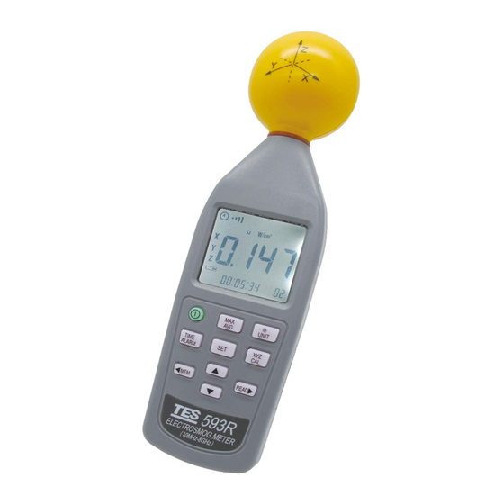
- Page 1 ELECTROSMOG METER INSTRUCTION MANUAL...
-
Page 2: Table Of Contents
CONTENTS Title Page SAFETY INFORMATION .............. 1 INTRODUCTION ................2 2-1 Fundamentals................2 2-2 Application..................3 2-3 Features ..................4 SPECIFICATIONS................. 5 3-1 General Specifications ..............5 3-2 Electrical Specifications..............6 OPERATION ................. 7 4-1 Front panel controls description ............ 7 4-2 LCD display description .............. -
Page 3: Safety Information
1. SAFETY INFORMATION CAUTION • Before making a measurement, check if the low battery symbol ) is shown on the display as soon as the meter is switched on. Change the battery if the symbol is displayed. • In the case of prolonged storage, it is preferable to remove the battery from the meter. -
Page 4: Introduction
2. INTRODUCTION 2-1 Fundamentals Electromagnetic pollution : This Meter used to indicate electromagnetic pollution generated artificially. Wherever there is a voltage or a current, the electric (E) and magnetic (H) fields arise. All types of radio broadcasting and TV transmitters produce electromagnetic fields, and they also arise in industry, business and the home, where they affect us even if our sense organs perceive nothing. -
Page 5: Application
The characteristic of electromagnetic fields : Electromagnetic fields propagate as waves and travel at the speed of light (c). The wavelength is proportional to the frequency. c (speed of light) λ(wavelength) = f (frequency) If the distance to the field source is less than three wavelength, then we are usually in the near-field. -
Page 6: Features
2-3 Features The meter is a broadband device for monitoring high-frequency radiation in the range from 10MHz to 8GHz. The non-directional electric field and high sensitivity also allow measurements of electric field strength in TEM cells and absorber rooms. The unit of measurement and the measurement types have been selected to expressed in units of electrical and magnetic field strength and power density. -
Page 7: Specifications
3. SPECIFICATIONS 3-1 General Specifications • Measurement method : Digital, triaxial measurement. • Directional characteristic : Isotropic, triaxial. • Measurement range selection : One continuous range. • Display resolution : 0.1mV/m, 0.1µA/m, 0.1µW/m , 0.001µW/cm • Setting time : Typically 1s (0 to 90% of measurement value). •... -
Page 8: Electrical Specifications
3-2 Electrical Specifications Unless otherwise stated, the following specifications hold under the following conditions : • The meter is located in the far-field of a source, the sensor head is pointed towards the source. • Ambient temperature : +23℃±3℃ • Relative air humidity : 25% to 75% Sensor type : Electrical field (E) Frequency range : 10MHz to 8GHz Specified measurement range :... -
Page 9: Operation
4. OPERATION 4-1 Front panel controls description (1). E-field sensor. (2). LCD display. (3). key : Press this key to turn the meter on or off. (4). key : Press this key to change sequential : “Instantaneous”→ “Max. instantaneous” → “Average” → “Max. average”. (5). - Page 10 (6). key : Press this key to switch to display date and time. Press and hold this key while turning the meter on to the alarm setting mode, press key two times to exit this mode. 3 Press this key for 3 seconds to switch the alarm function on or off. (7).
-
Page 11: Lcd Display Description
4-2 LCD display description (1). : Auto power off function on / off. (2). : Displayed : Audible sound function on / off. (3). MAX : Maximum measured value displayed. MAX AVG : Maximum average value displayed. (4). AVG : Average measured value displayed. (5). - Page 12 (10). : Manual data memory address number (1~99). : The manual data memory full indication. (11). ALARM : Alarm function on / off or alarm setting indication. (12). ▲ : When the alarm function is on , this is the indication if measured value exceeds the limit.
-
Page 13: Use E-Field Sensor
4-3 Use E-field sensor The actual 3-channel sensor is located in the head part of the meter. The three voltages generated by the sensor are fed back to the meter. In far-fields, an E-field sensor is preferable due to the greater bandwidth. The E-field sensor for frequencies is from 10MHz to 8GHz. - Page 14 • Maximum instantaneous (MAX) : The digital display shows the highest instantaneous value measured, the “MAX” symbol is displayed. • Average (AVG) : The digital display shows the average value measured, the “AVG” symbol is displayed. • Maximum average (MAX AVG) : The digital display shows the highest average value measured, the “MAX AVG”...
- Page 15 E-Field typically calibration data : Frequency 50MHz 2.13 100MHz 1.37 200MHz 1.19 300MHz 0.69 433MHz 0.78 500MHz 1.38 600MHz 2.12 700MHz 1.66 800MHz 1.40 900MHz 1.40 1.8GHz 2.06 2.4GHz 0.66 3.5GHz 1.05 5.4GHz 2.20 8.0GHz 3.16 4-4-4 Alarm limit value (ALARM) The alarm limit value is used to monitor the display value automatically.
-
Page 16: Setting The Meter
4-5 Setting the meter 4-5-1 Setting the units of measurement With the key as follows. Units Mannal data memory number (a). Electric field strength (V/m). (b). Computed magnetic field strength (mA/m). (c). Computed power density (mW/m (d). Computed power density (µW/cm 4-5-2 Setting the result mode Instantaneous result mode is automatically set when the meter is turned on. - Page 17 4-5-3 Setting the alarm limit value (ALARM) Power off Hold-on...
- Page 18 When the meter is normally turned on, the alarm set limit value will display for 2 seconds. 1. Press key to turn off the meter. 2. Press and hold on key, then press key to turn on the meter to enter the alarm setting mode, the “mW/m ”...
- Page 19 1. Press key to turn off the meter. 2. Press and hold on key, then press key to turn on the meter to enter the calibration factor setting mode, the “ CAL SEt ” marks is displayed. 3. Press key to increase or decrease the value. 4.
-
Page 20: Making Measurements
4-5-7 Setting the auto power off function off Auto power off symbol disappears Power off Hold-on When the meter is normally turned on, the auto power off function is on. 1. Press key to turn off the meter. 2. Press and hold key and turn on the meter again to disable the auto power off function, the “... -
Page 21: Manual Data Memory Storing Individual Measured Values
4-6-2 Long-term exposure measurements Location Place the meter between yourself and the suspected source of radiation. Make measurements at those points where parts of your body are nearest to the source of radiation. Note : Use the “Average ” or “Max average” modes only when the instantaneous measurement values are fluctuating greatly. - Page 22 4-7-2 Reading individual measured values Entry Reading mode indicate Reading memory location Exit 1. Press key, the display then shows “ ”(reading mode). 2. Press key to select the desired memory location. 3. Press key to select the desired reading units. 4.
-
Page 23: Setting Current Data And Time
1. Press to turn off the meter. 2. Press and hold and turn on the meter again, the display then shows “ CLr M ”, “ ” and “ ”, press key will exit and not clear memory. 3. Press to select “...
Need help?
Do you have a question about the PCE-EM 29 and is the answer not in the manual?
Questions and answers