Table of Contents
Advertisement
User's Guide
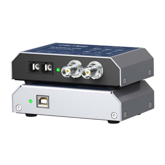
MADIface USB
Portable MADI via USB!
™
TotalMix
24 Bit / 192 kHz
™
™
™
SyncAlign
ZLM
SyncCheck
™
SteadyClock
USB 2.0 Digital I/O System
64 Channels MADI Interface
2 Channels AES Recording
24 Bit / 192 kHz Digital Audio
128 x 128 Matrix Router
MADI, AES and Word Sync
MIDI embedded in MADI
Stand-Alone Operation
Advertisement
Table of Contents
Troubleshooting

Related Manuals for RME Audio MADIface USB


Summary of Contents for RME Audio MADIface USB
- Page 1 User's Guide MADIface USB Portable MADI via USB! ™ TotalMix 24 Bit / 192 kHz ™ ™ ™ SyncAlign SyncCheck ™ SteadyClock USB 2.0 Digital I/O System 64 Channels MADI Interface 2 Channels AES Recording 24 Bit / 192 kHz Digital Audio...
-
Page 2: Table Of Contents
15.1 MIDI doesn't work ..........27 15.2 Repairing Disk Permissions .........27 15.3 Supported Sample Rates........27 15.4 Channel Count under Core Audio......27 15.5 Various Information ..........28 Using more than one MADIface ......28 DIGICheck Mac ............29 Hotline – Troubleshooting........30 User's Guide MADIface USB © RME... - Page 3 23.7 MS Processing............. 59 MIDI Remote Control 24.1 Overview .............. 60 24.2 Mapping ............... 60 24.3 Setup..............61 24.4 Operation ............. 61 24.5 MIDI Control............62 24.6 Loopback Detection ..........63 24.7 OSC (Open Sound Control)......... 63 User's Guide MADIface USB © RME...
- Page 4 26.3 Latency and Monitoring........70 26.4 USB Audio............71 26.5 DS – Double Speed ..........72 26.6 QS – Quad Speed..........72 26.7 SteadyClock ............73 26.8 Terminology ............73 Miscellaneous Accessories .............76 Warranty..............76 Appendix ..............77 Declaration of Conformity ........78 User's Guide MADIface USB © RME...
-
Page 5: General
User's Guide MADIface USB General User's Guide MADIface USB © RME... -
Page 6: Introduction
MADI audio to a Mac or PC. The latest Plug and Play technology guarantees a sim- ple installation, even for the inexperienced user. The numerous unique features and well thought-out configuration dialog puts the MADIface USB at the very top of the range of com- puter-based audio interfaces. -
Page 7: First Usage - Quick Start
TotalMix FX select either 64 Channel Mix or 128 Channel Mix. The MADIface USB can be used stand-alone, connected to standard USB 5V power supplies. It does not remember any setting but uses a fixed internal mode, see chapter 19 for details. - Page 8 User's Guide MADIface USB © RME...
-
Page 9: Installation And Operation - Windows
User's Guide MADIface USB Installation and Operation - Windows User's Guide MADIface USB © RME... -
Page 10: Hardware, Driver And Firmware Installation
'Update' button. A progress bar will indicate when the flash process is finished (Verify Ok). After the update the unit needs to be reset. This is done by unplugging the MADIface USB for a few seconds. A reboot of the computer is not necessary. -
Page 11: Configuring The Madiface Usb Settings Dialog
7. Configuring the MADIface USB 7.1 Settings Dialog - General Configuration of the MADIface USB is done via its own settings dialog. The panel Settings can be opened: • by clicking on the fire symbol in the Task Bar's notification area The mixer of the MADIface USB, TotalMix FX, can be opened: •... - Page 12 Input defines the currently used main input, Optical or Coaxial. AutoSelect activates an auto- matic input selection. Using both inputs with MADI at the same time, AutoSelect puts the device into Seamless Redundancy mode. The MADIface USB will switch to the other input in real-time if the current one fails.
-
Page 13: Wdm Configuration
So while most users can disregard this function, some will use software that needs the property. We are even aware of custom software that needs more than one ‘Speaker’ to work correctly. RME’s driver gives the user the freedom to configure whatever is needed to work properly. User's Guide MADIface USB © RME... - Page 14 The screenshot to the right shows the stereo WDM devices available with the MADIface USB, and that only MADI 1/2 has been activated. Any number can be activated. Also only higher numbered devices might be active. For example...
- Page 15 7.1, in the Windows Sound control panel by selecting the playback device and clicking the Configure button. An up to 8-channel playback using the Windows Media Player requires the speaker setup 7.1 Surround. User's Guide MADIface USB © RME...
-
Page 16: Operation And Usage Playback
Note: Since Vista the audio application can no longer control the sample rate under WDM. Therefore the driver of the MADIface USB includes a workaround: the sample rate can be set globally for all WDM devices within the Settings dialog, see chapter 7.1. -
Page 17: Dvd-Playback (Ac-3/Dts)
MADI (1 to 16) MADI (1 to 16) MADI (1 to 16) MADI (17 to 32) MADI (17 to 32) MADI (17 to 32) MADI (33 to 64) MADI (33 to 64) MADI (33 to 64) User's Guide MADIface USB © RME... -
Page 18: Multi-Client Operation
The MADIface USB inputs can be used simultaneously. In that case the MADIface USB has to be told which one of the signals is the sync reference - a digital device can only be clocked from a single source. -
Page 19: Operation Under Asio General
9. Operation under ASIO 9.1 General Start the ASIO software and select ASIO MADIface USB as the audio I/O device or the audio driver. The MADIface USB supports ASIO Direct Monitoring (ADM). Both MME MIDI and DirectMusic MIDI can be used. -
Page 20: Known Problems
10. Using more than one MADIface The current driver supports up to three MADIface USB. All units have to be in sync, i.e. have to receive valid sync information (by feeding synchronized signals). •... -
Page 21: Digicheck Windows
Here you usually find two entries of a USB2 Enhanced Host Controller. All USB devices are connected via a Root Hub, the MADIface USB will show up here too. By a simple reconnection to other ports this view lets you check to which one of the two controllers the MADIface is con- nected to. -
Page 22: Hotline - Troubleshooting
• Check that there is a valid signal at the input. If so, the current sample frequency is dis- played in the Settings dialog. • Check whether the MADIface USB has been selected as recording device in the audio ap- plication. - Page 23 User's Guide MADIface USB Mac OS X – Installation and Operation User's Guide MADIface USB © RME...
-
Page 24: Hardware, Driver And Firmware Installation
If so, simply press the 'Update' button. A progress bar will indicate when the flash process is finished (Verify Ok). After the update the unit needs to be reset. This is done by unplugging the MADIface USB for a few seconds. A reboot of the computer is not necessary. -
Page 25: Configuring The Madiface Usb
14.1 Settings Dialog Configuring the MADIface USB is done via its own Settings dialog. Start the program Fireface USB Settings. The mixer of the MADIface USB can be configured by starting the program To- talMix FX. The MADIface hardware offers a number of helpful, well thought-of practical functions and op- tions which affect how the card operates - it can be configured to suit many different require- ments. -
Page 26: Clock Modes - Synchronization
The MADIface USB inputs operate simultaneously. Because there is no input selector in some modes, the MADIface USB has to be told which one of the signals is the sync reference - a digital device can only be clocked from a single source. The Clock Source selection is used to define a preferred input for the automatic clock system. -
Page 27: Mac Os X Faq
But not any software will support all the hardware's sample rates. The hardware's capabilities can easily be verified in the Audio MIDI Setup – Audio Window. Select the MADIface USB. A click on Format will show the full list of supported sample rates. -
Page 28: Various Information
This function is found in the Audio MIDI Setup – Audio Window. Click the + sign in the lower left. The current driver supports up to three MADIface USB. All units have to be in sync, i.e. have to receive valid sync information (by feeding synchronized signals). -
Page 29: Digicheck Mac
To install DIGICheck, go to the \DIGICheck directory on the RME Driver CD and run setup.exe. Follow the instructions prompted on the screen. DIGICheck is constantly updated. The latest version is always available on our website www.rme-audio.com, section Downloads / DIGICheck. User's Guide MADIface USB © RME... -
Page 30: Hotline - Troubleshooting
• Check that there is a valid signal at the input. If so, the current sample frequency is dis- played in the Settings dialog. • Check whether the MADIface USB has been selected as recording device in the audio ap- plication. -
Page 31: Stand-Alone Operation, Connections
User's Guide MADIface USB Stand-Alone Operation and Connections User's Guide MADIface USB © RME... -
Page 32: Stand-Alone Operation
19. Stand-alone Operation 19.1 General The MADIface USB can be powered by any USB power wall wart or USB battery, like those for mobile phones and MP3 players. Without a computer host the device enters a pre-configured operation mode which is part of its firmware, thus cannot be modified by the user. -
Page 33: Connections
HDSP(e) MADI cards or MADIfaces. Additionally MIDI data can be transmitted from/to other RME devices with MADI ports, and both can be MIDI remote controlled without any additional line or cabling between computer (MADIface) and unit. User's Guide MADIface USB © RME... - Page 34 User's Guide MADIface USB © RME...
-
Page 35: Totalmix Fx
User's Guide MADIface USB TotalMix FX User's Guide MADIface USB © RME... -
Page 36: Totalmix: Routing And Monitoring
21. TotalMix: Routing and Monitoring 21.1 Overview The MADIface USB includes a powerful digital real-time mixer, TotalMix FX, based on RME’s unique, sample-rate independent TotalMix technology. It allows for practically unlimited mixing and routing operations, with all inputs and playback channels simultaneously, to any hardware outputs. - Page 37 User's Guide MADIface USB © RME...
-
Page 38: The User Interface
The visual design of the TotalMix mixer is a result of its capability to route hardware inputs and software playback channels to any hardware output. The MADIface USB provides 64 input channels, 64 software playback channels, and 64 hardware output channels: TotalMix can be used in the above view (View Options 2 Rows). -
Page 39: The Channels
The arrow symbol at the bottom minimizes the channel width to that of the level meters. An- other click maximizes it again. A mouse click with held Ctrl key causes all channels to the right to enlarge and minimize at once. User's Guide MADIface USB © RME... - Page 40 The gain (fader knob position) of the currently active routing (the submix selected in the third row) is shown as white triangle. Background: TotalMix has no fixed channel fader. In case of the MADIface USB there are 32 stereo Aux sends, shown alternately as single fader within the channel strip.
-
Page 41: Settings
Main Out. With this any hardware output can be controlled and listened to through the monitoring output very conveniently. Using the option Assign / Cue to in the Control Room section, Cue can also be used with any of the Phones outputs. User's Guide MADIface USB © RME... -
Page 42: Section Control Room
1 to 16, as at 192 kHz the other channels are not available anymore. The output for the Cue signal, which is usually Main, can also be set to one of the Phones outputs. This setting also controls the PFL monitoring. User's Guide MADIface USB © RME... -
Page 43: The Control Strip
Device selection. Select the unit to be controlled in case more than one is installed on the computer. FX. Not functional with the MADIface USB. Undo / Redo. With the unlimited Undo and Redo changes of the mix can be undone and redone, at any time. -
Page 44: View Options
Here one works with the routings fields of the input and playback channels only, which then show different routing destinations. Level Meters Post FX. Not functional with the MADIface USB. RMS Level. The numerical level display in the channels displays peak or RMS. Show FX. -
Page 45: Snapshots - Groups
MIDI or OSC remote control. Hide Channel in MIDI Remote 1-4. The selected channels are hidden for MIDI remote (CC and Mackie Protocol). Hide Channel in OSC Remote 1-4. The selected channels are hidden for OSC remote control. User's Guide MADIface USB © RME... - Page 46 Layout Preset. That makes it very easy to see and to verify which channels are mixed/routed to the current output. Sub makes checking and verifying of mixes, but also the mix editing itself, a lot easier, and maintains perfect overview even with lots of channels. User's Guide MADIface USB © RME...
-
Page 47: Scroll Location Marker
When the TotalMix FX window is intentionally made small in width, so only a few channels are shown. • When some or all Settings panels are open. Then all settings are always visible, but require a lot of space horizontally. User's Guide MADIface USB © RME... -
Page 48: Preferences
Disable double click fader action. Prevents unintentional gain settings, for example when using sensitive touch- pads. Dynamic Meters Not supported by the MADIface USB, as these settings refer to Compressor and Expander from other RME devices. Snapshots Do not load Main volume/balance. -
Page 49: Store For Current Or All Users (Windows)
TotalMix FX is restarted. The xml-file is updated on exit, so simply set up TotalMix as desired and exit it (right mouse click on the symbol in the notification area). User's Guide MADIface USB © RME... -
Page 50: Settings
TotalMix in a live environment, as it allows to quickly listen/monitor any of the inputs by hitting the Solo button. The monitoring happens on the output set for the Cue signal via the Assign dialog. User's Guide MADIface USB © RME... -
Page 51: Midi Page
TotalMix level meters in the preferences. Note: When MIDI Out is set to NONE then TotalMix FX can still be controlled by Mackie Control MIDI commands, but the 8-channel block is not marked as remote target. User's Guide MADIface USB © RME... -
Page 52: Osc Page
Options Send Peak Level. Activates transmission of the peak level meter data. Peak Hold activates the peak hold function as set up for the TotalMix level meters in the preferences. User's Guide MADIface USB © RME... -
Page 53: Aux Devices
ADAT, AES/EBU and MADI, plus 4 channels of DA-conversion for monitoring. It can be used as universal front-end for the MADIface USB and other interfaces. To simplify operation the most important parameters of the XTC (gain, 48V, phase, mute, AutoSet) can be controlled directly from the TotalMix FX input channels. -
Page 54: Hotkeys And Usage
DIGICheck). The dialog Preferences is opened with F3. Alt-F4 closes the current window. Alt and number keys 1 to 8 (not on the numeric keypad!) will load the corresponding Work- space from the Workspace Quick Select feature (hotkey W). User's Guide MADIface USB © RME... -
Page 55: Menu Options
Clear all submixes. Deletes all submixes. Clear channel effects. Not valid for the MADIface USB. Set output volumes. All third row faders will be set to 0 dB, Main and Speaker B to -10 dB. -
Page 56: Menu Window
Each change in one view is immediately reflected in the other view as well. 22.2 Elements of the Matrix View The visual design of the TotalMix Matrix is determined by the architecture of the MADIface USB: Horizontal labels. All hardware outputs Vertical labels. All hardware inputs. Below are all playback channels. -
Page 57: Tips And Tricks
The easiest and quickest way to delete complex routings is by selection of the according output channel in the mixer view by a right mouse click, and selection of the menu entry Clear Submix. As TotalMix FX includes an unlimited undo the delete process can be undone easily. User's Guide MADIface USB © RME... -
Page 58: Copy And Paste Everywhere
The block diagram shows how the software's input signal is played back, and fed back from the hardware output to the software input. User's Guide MADIface USB © RME... -
Page 59: Ms Processing
Low Cut, Expander, Compressor or Delay. The most basic application is the manipulation of the stereo width: a change of the level of the side channel allows to manipulate the stereo width from mono to stereo up to extended. User's Guide MADIface USB © RME... -
Page 60: Midi Remote Control
Additionally, the stereo output faders (lowest row) which are set up as Main Out in the Control Room section can also be controlled by the standard Control Change Volume via MIDI chan- nel 1. With this, the main volume of the MADIface USB is controllable from nearly any MIDI equipped hardware device. -
Page 61: Setup
TotalMix also supports the 9th fader of the Mackie Control. This fader (labelled Master) will con- trol the stereo output fader (lowest row) which is set up as Main Out in the Control Room sec- tion. User's Guide MADIface USB © RME... -
Page 62: Midi Control
24.5 MIDI Control The hardware output set up as Main Out can be controlled by the standard Control Change Volume via MIDI channel 1. With this, the main volume of the MADIface USB is controllable from nearly any MIDI equipped hardware device. -
Page 63: Loopback Detection
RME offers a free iPad template for the iOS app TouchOSC (by Hexler, available in the Apple App-Store): http://www.rme-audio.de/download/tosc_tm_ipad_template.zip A template for Lemur is available from liine.net, the makers of Lemur. The RME forum hosts further information, more templates (even for the iPhone) and lots of useful user feedback. User's Guide MADIface USB © RME... - Page 64 User's Guide MADIface USB © RME...
-
Page 65: Technical Reference
User's Guide MADIface USB Technical Reference User's Guide MADIface USB © RME... -
Page 66: Technical Specifications
• Jitter suppression of external clocks: about 30 dB (2.4 kHz) • Input PLL ensures zero dropout, even at more than 100 ns jitter • Supported sample rates: 28 kHz up to 200 kHz User's Guide MADIface USB © RME... -
Page 67: Firmware
At the time of writing this manual the MADIface USB is shipped with firmware 22. The firmware version is displayed in the Settings dialog as well as the Firmware Update Tool. -
Page 68: Technical Background
2 km. Single mode allows for much longer distances, but it uses a completely different fibre (8 µm). By the way, due to the wave-length of the light being used (1300 nm), the opti- cal signal is invisible to the human eye. User's Guide MADIface USB © RME... -
Page 69: Lock And Synccheck
In practice, SyncCheck allows for a quick overview of the correct configuration of all digital de- vices. So one of the most difficult and error-prone topics of the digital studio world finally be- comes easy to handle. User's Guide MADIface USB © RME... -
Page 70: Latency And Monitoring
RME's Zero Latency Monitoring. The term describes the digital path of the audio data from the input of the interface to its output. The digital receiver of the MADIface USB can't operate un-buffered, and together with TotalMix and the output via the transmitter, it causes a typical delay of 3 samples. -
Page 71: Usb Audio
Under OS X, every audio interface has to use a so called Safety Offset, otherwise Core Audio won't operate click-free. The MADIface USB uses a safety offset of 24 samples. This offset is signalled to the system, and the software can calculate and display the total latency of buffer size plus AD/DA offset plus 2 x Safety Offset plus Safety Buffer for the current sample rate. -
Page 72: Ds - Double Speed
MADI channels. This reduces the available channel count from 64 to 16. As the transmission of quad rate signals with 48K Frame is done at standard sample rate (Sin- gle Speed), the MADI ports still operate at 44.1 kHz or 48 kHz. User's Guide MADIface USB © RME... -
Page 73: Steadyclock
DVD Audio. Single Wire Standard audio data transfer, where the audio signal's sample rate is equal to the rate of the digital signal. Used from 32 to 192 kHz. Sometimes called Single Wide. User's Guide MADIface USB © RME... - Page 74 Frame using S/MUX: the receiver can detect the real (double) sample rate on its own and im- mediately. With 48K Frame and S/MUX, the user has to set up the correct sample rate in all involved devices manually. User's Guide MADIface USB © RME...
-
Page 75: Miscellaneous
User's Guide MADIface USB Miscellaneous User's Guide MADIface USB © RME... -
Page 76: Accessories
Audio AG does not accept claims for damages of any kind, especially consequential damage. Liability is limited to the value of the MADIface USB. The general terms of business drawn up by Audio AG apply at all times. -
Page 77: Appendix
RME Driver CD, or any commercial exploitation of these media without express written permis- sion from RME Intelligent Audio Solutions is prohibited. RME reserves the right to change specifications at any time without notice. User's Guide MADIface USB © RME... -
Page 78: Declaration Of Conformity
Synthax United States, 6600 NW 16th Street, Suite 10, Ft Lauderdale, FL 33313 T.:754.206.4220 Trade Name: RME, Model Number: MADIface USB This equipment has been tested and found to comply with the limits for a Class B digital device, pursuant to Part 15 of the FCC Rules.
Need help?
Do you have a question about the MADIface USB and is the answer not in the manual?
Questions and answers