Table of Contents
Advertisement
User's Guide
Fireface UFX+
TM
The most powerful Thunderbolt
and USB audio interface ever!
™
TotalMix FX
24 Bit / 192 kHz
™
™
™
SyncAlign
ZLM
SyncCheck
™
SteadyClock
TM
USB 3.0 / Thunderbolt
Digital I/O System
12 + 16 + 2 Channels Analog / ADAT / AES Interface
64 Channels MADI Interface
24 Bit / 192 kHz Digital Audio
188 x 94 Matrix Router
2 x MIDI I/O
Full Stand-Alone Operation
Class Compliant Operation
MIDI Remote Control
Advertisement
Table of Contents
Troubleshooting

Related Manuals for RME Audio Fireface UFX+


Summary of Contents for RME Audio Fireface UFX+
- Page 1 User's Guide Fireface UFX+ The most powerful Thunderbolt and USB audio interface ever! ™ TotalMix FX 24 Bit / 192 kHz ™ ™ ™ SyncAlign SyncCheck ™ SteadyClock USB 3.0 / Thunderbolt Digital I/O System 12 + 16 + 2 Channels Analog / ADAT / AES Interface 64 Channels MADI Interface 24 Bit / 192 kHz Digital Audio 188 x 94 Matrix Router...
-
Page 2: Table Of Contents
Important Safety Instructions ........6 General Introduction ...............8 Package Contents .............8 System Requirements ..........8 Brief Description and Characteristics.....8 First Usage - Quick Start Connectors – Controls - Display ......9 Quick Start ............11 Installation and Operation - Windows Hardware, Driver and Firmware Installation Hardware and Driver Installation......14 De-installing the Drivers........14 Firmware Update..........14... - Page 3 Installation and Operation - Mac OS X Hardware, Driver and Firmware Installation 13.1 Hardware and Driver Installation ......32 13.2 De-installing the Drivers........32 13.3 Firmware Update ..........33 Configuring the Fireface 14.1 Settings Dialog............. 33 14.2 Clock Modes - Synchronization ......36 Mac OS X FAQ 15.1 MIDI doesn't work ..........
- Page 4 TotalMix FX Routing and Monitoring 25.1 Overview ..............54 25.2 The User Interface ..........56 25.3 The Channels............57 25.3.1 Settings ............59 25.3.2 Equalizer ............60 25.3.3 Dynamics .............62 25.4 Section Control Room ..........63 25.5 The Control Strip ..........64 25.5.1 View Options ..........65 25.5.2 Snapshots - Groups ........66 25.5.3 Channel Layout –...
- Page 5 Class Compliant Mode General..............92 System Requirements ..........92 Operation ..............93 32.1 Useful Hints............93 32.2 Class Compliant under Windows/Mac OS X ..94 Supported Inputs and Outputs......94 Front panel Operation ..........95 Audio Routing and Processing ......95 Setups ..............
-
Page 6: Important Safety Instructions
Important Safety Instructions ATTENTION! Do not open chassis – risk of electric shock The unit has non-isolated live parts inside. No user serviceable parts inside. Refer service to qualified service personnel. Mains • The device must be earthed – never use it without proper grounding •... -
Page 7: General
User's Guide Fireface UFX+ General User's Guide Fireface UFX+ © RME... -
Page 8: Introduction
1. Introduction Thank you for choosing the Fireface UFX+. This unique audio system is the premier solution to transfer analog and digital audio data directly to a computer from practically any source. Nu- merous unique features, well thought-out configuration dialogs, an industry-leading mixing en- gine and monitoring solution, professional DSP effects and class-leading analog circuits with latest digital converters put the Fireface UFX+ at the very top of the range of computer-based audio interfaces. -
Page 9: First Usage - Quick Start
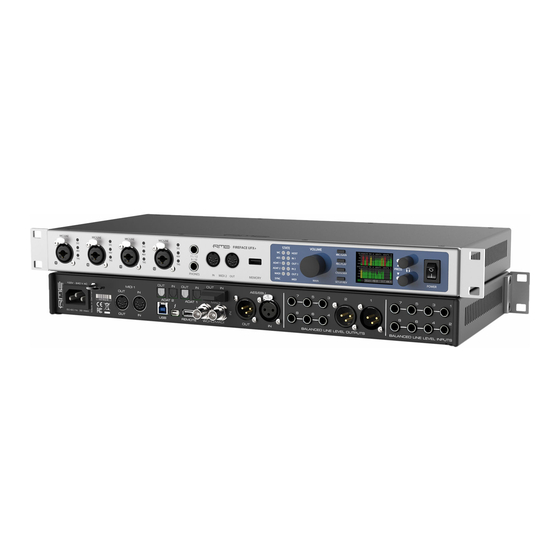
5. First Usage – Quick Start 5.1 Connectors – Controls – Display The front of the Fireface UFX+ features four combined instrument / microphone inputs, two stereo headphone outputs, three rotary encoders with push functionality, a graphical colour display, one MIDI input and output, a USB connector for DURec, and several status LEDs. The Neutrik combo sockets of the four Mic/Line inputs provide XLR and 6.3 mm / 1/4"... - Page 10 The rear panel of the Fireface UFX+ features eight more analog inputs and outputs, the power socket, and all digital inputs and outputs: Balanced Line Level Inputs. 8 balanced analog inputs via 6.3 mm stereo TRS connectors. Balanced Line Level Outputs. 8 balanced analog outputs, six via 6.3 mm stereo TRS, two via XLR.
-
Page 11: Quick Start
5.2 Quick Start After the driver installation (chapter 6 / 13) connect the TRS jacks or the XLR inputs with the analog signal source. The input sensitivity of the rear inputs can be changed in TotalMix (Input Channel Settings, LoGain / +4 dBu and Gain), assuring the highest signal to noise ratio will be achieved. - Page 12 User's Guide Fireface UFX+ © RME...
-
Page 13: Installation And Operation - Windows
User's Guide Fireface UFX+ Installation and Operation – Windows User's Guide Fireface UFX+ © RME... -
Page 14: Hardware, Driver And Firmware Installation
6. Hardware, Driver and Firmware Installation 6.1 Hardware and Driver Installation To simplify installation it is recommended to first install the drivers before the unit is connected to the computer. But it will also work the other way round. Insert the RME Driver CD into your CD-ROM drive. The driver installer is located in the directory \Thunderbolt for Thunderbolt \MADIface_USB for USB 3 and USB 2.0 (NOT Fireface_USB) Start rmeinstaller.exe and follow the instructions of the installer. -
Page 15: Configuring The Fireface
7. Configuring the Fireface 7.1 Settings dialog – Main Tab Configuration of the Fireface UFX+ is done via its own settings dialog. The panel Settings can be opened by clicking on the fire or hammer symbol in the Task Bar's system tray. The mixer of the Fireface UFX+, TotalMix FX, can be opened by clicking on the DSP FX symbol in the Task Bar's system tray The hardware of the Fireface UFX+ offers a number of helpful, well thought-of practical func-... - Page 16 Buffer Size The setting Buffer Size determines the latency between incoming and outgoing ASIO and WDM data, as well as affecting system stability (see chapter 9.1). USB Diagnosis and Errors does not refer to buffer errors, but USB transmission errors. The display will be reset on any start of a playback/record.
- Page 17 WDM Devices Allows to freely set which I/Os are available as WDM devices, if these are stereo or multi- channel devices (up to 8 channels), and if one or multiple of the currently active WDM devices should have the Speaker property. More details are found in chapter 7.2. Clock Mode Word Clock –...
-
Page 18: Option Wdm Devices
7.2 Option WDM Devices The WDM Devices configuration has one button to enter the edit dialog, a status display show- ing the number of currently enabled WDM devices, and a listbox to change between Stereo or Multi-Channel devices. The number represents both record and playback devices, so ‘1’... - Page 19 Changing to the tab Speaker presents a list of all currently activated WDM devices. Any of these can now get the Speaker property. Please note that defining more than one device as Speaker usually makes no sense, and the speakers also don’t get numbered or renamed in Windows, so it is impossible to find out which one is which.
-
Page 20: Tab Global (Thunderbolt Only)
7.3 Tab Global (Thunderbolt only) This tab includes several options that work on all currently installed and supported interfaces. Lock Registry Default: off. Checking this option brings up a dialog to enter a password. Changes in the Set- tings dialog are no longer written to the registry. As the settings are always loaded from the registry when starting the computer, this method provides an easy way to define an initial state of the Fireface UFX+. -
Page 21: Pitch (Thunderbolt Only)
7.4 Pitch (Thunderbolt only) Usually soundcards and audio interfaces generate their internal clock (master mode) by a quartz. Therefore the internal clock can be set to 44.1 kHz or 48 kHz, but not to a value in be- tween. SteadyClock, RME's sensational Low Jitter Clock System, is based on a Direct Digital Synthesizer (DDS). -
Page 22: Operation And Usage Playback
8. Operation and Usage 8.1 Playback The Fireface UFX+ can play back audio data in supported formats only (sample rate, bit resolu- tion). Otherwise an error message appears (for example at 22 kHz and 8 bit). In the audio application being used, Fireface must be selected as output device. This can often be found in the Options, Preferences or Settings menus under Playback Device, Audio Devices, Audio etc. -
Page 23: Dvd-Playback (Ac-3/Dts)
8.2 DVD-Playback (AC-3/DTS) AC-3 / DTS When using popular DVD software players like WinDVD and PowerDVD, their audio data stream can be sent to any AC-3/DTS capable receiver using the Fireface's SPDIF output. For this to work, the WDM SPDIF device of the Fireface has to be selected in >Control Panel/ Sound/Playback<... -
Page 24: Channel Count Under Wdm
Fireface MADI (33-64) 8.4 Multi-client Operation RME audio interfaces support multi-client operation. Several programs can be used at the same time. The formats ASIO and WDM can even be used on the same playback channels simulta- neously. But as WDM uses a real-time sample rate conversion (ASIO does not), all active ASIO software has to use the same sample rate. -
Page 25: Analog Recording
8.5 Analog Recording For recordings via the analog inputs the corresponding record device has to be chosen (Fire- face UFX+ Analog (x+x)). The input sensitivity of the rear inputs can be changed in two steps and with adjustable gain in TotalMix (Input Channel Settings, Level), assuring the highest signal to noise ratio will be achieved. -
Page 26: Clock Modes - Synchronization
8.7 Clock Modes - Synchronization In the digital world, all devices must be either Master (clock source) or Slave (clock receiver). Whenever several devices are linked within a system, there must always be a single master clock. A digital system can only have one master! If the Fireface’s clock mode is set to 'Master', all other devices must be set to ‘Slave’. -
Page 27: General
9. Operation under ASIO 9.1 General Start the ASIO software and select RME Thunderbolt ASIO or ASIO MADIface USB as the audio I/O device or the ASIO audio driver. The Fireface UFX+ supports ASIO Direct Monitoring (ADM). The Fireface UFX+ MIDI I/Os can be used with both MME MIDI and DirectMusic MIDI. 9.2 Channel Count under ASIO At a sample rate of 88.2 or 96 kHz, the ADAT optical input and outputs operate in S/MUX mode, so the number of available channels per port is reduced from 8 to 4. -
Page 28: Known Problems
9.3 Known Problems If a computer does not provide sufficient CPU-power, and/or sufficient USB or PCI bus transfer rates, and/or sufficient PCIe-bus transfer rates, then drop outs, crackling and noise will appear. Raising the buffer size in the Settings dialog of the Fireface UFX+ helps in most cases. It is also recommended to deactivate all PlugIns to verify that these are not the reason for such effects. -
Page 29: Digicheck Windows
11. DIGICheck Windows The DIGICheck software is a unique utility developed for testing, measuring and analysing digi- tal audio streams. Although this Windows software is fairly self-explanatory, it still includes a comprehensive online help. DIGICheck 5.82 operates as multi-client ASIO host, therefore can be used in parallel to any software, be it WDM or ASIO, with both inputs and outputs (!). -
Page 30: Hotline - Troubleshooting
12. Hotline – Troubleshooting The newest information can always be found on our website www.rme-audio.com, section FAQ, Latest Additions. The second port ADAT channels don’t seem to work • The optical output ADAT2 has been switched to AES/SPDIF. As can be seen in the block diagram, all channels and their assignments still exist, but the optical transmitter has been disconnected from ADAT2 and is now fed from the AES output (channels 13/14). -
Page 31: Installation And Operation - Mac Os X
User's Guide Fireface UFX+ Installation and Operation – Mac OS X User's Guide Fireface UFX+ © RME... -
Page 32: Hardware, Driver And Firmware Installation
13. Hardware, Driver and Firmware Installation 13.1 Hardware and Driver Installation After the Fireface has been connected to the computer and switched on install the drivers from the RME Driver CD. The driver files are located in the folder \MADIface_USB and \Thunderbolt. -
Page 33: Firmware Update
13.3 Firmware Update The Flash Update Tool updates the firmware of the Fireface UFX+ to the latest version. It re- quires an already installed Thunderbolt or USB driver. Start the program RME UFX+ Flash Update Tool. The Flash Update Tool displays the current revision of the UFX+ firmware, and whether it needs an update or not. - Page 34 Input Options Word Clock - Termination Checking this option terminates the word clock input internally with 75 Ohms. Optical 2 In SPDIF will turn the optical input into an optical SPDIF input, ADAT into an ADAT input (default). Please note that using the optical input with SPDIF disables the AES input via XLR. MADI Input Options: Optical - default.
- Page 35 Sample Rate Used to set the current sample rate. This is the same setting as in the Audio MIDI Setup, just added here for your convenience. Clock Source The unit can be configured to use its own clock (Internal = Master), or one of the input signals (Word, AES, ADAT1, ADAT2, MADI optical, MADI coaxial).
-
Page 36: Clock Modes - Synchronization
14.2 Clock Modes - Synchronization In the digital world, all devices must be either Master (clock source) or Slave (clock receiver). Whenever several devices are linked in a system, there must always be a single master clock. A digital system can only have one master! If the Fireface’s clock mode is set to 'Master', all other devices must be set to ‘Slave’. -
Page 37: Mac Os X Faq
15. Mac OS X FAQ 15.1 MIDI doesn't work In some cases the applications do not show the MIDI port. The reason for this is usually visible within the Audio MIDI Setup. It displays no RME MIDI device, or the device is greyed out and therefore inactive. -
Page 38: Various Information
15.5 Various Information The driver of the Fireface requires at least Mac OS 10.6. Programs that don't support card or channel selection will use the device chosen as Input and Output in the System Preferences – Sound panel. Via Launchpad – Other – Audio MIDI Setup the Fireface can be configured for the system wide usage in more detail. -
Page 39: Digicheck Mac
17. DIGICheck Mac The DIGICheck software is a unique utility developed for testing, measuring and analysing digi- tal audio streams. Although the software is fairly self-explanatory, it still includes a comprehen- sive online help. DIGICheck 0.70 operates in parallel to any software, showing all input data. The following is a short summary of the currently available functions: •... -
Page 40: Hotline - Troubleshooting
18. Hotline – Troubleshooting The newest information can always be found on our website www.rme-audio.com, section FAQ, latest Additions. The unit and drivers have been installed correctly, but playback does not work: • Is Fireface UFX+ listed in the System Profiler? (Vendor ID 2613). •... -
Page 41: Inputs And Outputs
User's Guide Fireface UFX+ Inputs and Outputs User's Guide Fireface UFX+ © RME... -
Page 42: Analog Inputs
19. Analog Inputs 19.1 Line Rear The Fireface has eight balanced Line inputs as 1/4" TRS jacks on the back of the unit. The elec- tronic input stage is built in a servo balanced design which handles unbalanced (mono jacks) and balanced (stereo jacks) correctly, automatically adjusting the level reference. -
Page 43: Analog Outputs
20. Analog Outputs 20.1 Line The short circuit protected, low impedance line outputs of channels 3 to 8 are available as 1/4" TRS jacks on the back of the unit. The electronic output stage is built in a servo balanced de- sign which handles unbalanced (mono jacks) and balanced (stereo jacks) correctly. -
Page 44: Digital Connections
In case the Phones outputs should operate as line outputs, an adapter TRS plug to RCA phono plugs, or TRS plug to TS plugs is required. The pin assignment follows international standards. The left channel is connected to the tip, the right channel to the ring of the TRS jack/plug. -
Page 45: Madi
Input Thanks to a highly sensitive input stage SPDIF coaxial can be fed too by using a simple cable adapter phono/XLR. To achieve this, pins 2 and 3 of a male XLR plug are connected individually to the two pins of a phono plug. The cable shielding is only connected to pin 1 of the XLR - not to the phono plug. -
Page 46: Midi
21.4 MIDI Fireface UFX+ offers two MIDI I/O via four 5-pin DIN sockets. The MIDI ports are added to the system by the driver. Using MIDI capable software, these ports can be accessed under the name UFX+ MIDI Port. All RME MADI devices support the invisible transmission of MIDI via MADI. MIDI data can be transmitted from/to other RME devices with MADI ports, without any additional line or cabling between computer (MADI interface) and external units. -
Page 47: Technical Description And Background
The received word clock signal can be distributed to other devices by using the word clock out- put. With this the usual T-adapter can be avoided, and the Fireface UFX+ operates as Signal Refresher. This kind of operation is highly recommended, because •... -
Page 48: Cables And Termination
22.3 Cabling and Termination Word clock signals are usually distributed in the form of a network, split with BNC T-adapters and terminated with resistors. We recommend using off-the-shelf BNC cables to connect all devices, as this type of cable is used for most computer networks. You will find all the neces- sary components (T-adapters, terminators, cables) in most electronics and/or computer stores. -
Page 49: Stand-Alone Operation
User's Guide Fireface UFX+ Stand-Alone Operation User's Guide Fireface UFX+ © RME... -
Page 50: Operation And Usage
23. Operation and Usage 23.1 General Using the three rotary encoders and the clear colour display the Fireface UFX+ can be config- ured and set up completely at the device. Additionally internal memory allows for the permanent storage of six different states of the unit. Therefore the Fireface UFX+ is able to operate fully stand-alone, without any connected computer. -
Page 51: Examples
24. Examples 24.1 12-Channel AD/DA-Converter TotalMix' super-flexible routing functions make it easy to turn the UFX into a 12-channel AD/DA converter. It’s easy to build the setup. For a clean start perform a Total Reset from the Options menu. Then select the ADAT Output 1/2 in the third row, and pull up the faders of the Analog input 1/2 in the first row. - Page 52 User's Guide Fireface UFX+ © RME...
-
Page 53: Totalmix Fx
User's Guide Fireface UFX+ TotalMix FX User's Guide Fireface UFX+ © RME... -
Page 54: Routing And Monitoring
25. Routing and Monitoring 25.1 Overview The Fireface UFX+ includes a powerful digital real-time mixer, the Fireface UFX+ mixer, based on RME’s unique, sample-rate independent TotalMix technology. It allows for practically unlim- ited mixing and routing operations, with all inputs and playback channels simultaneously, to any hardware outputs. - Page 55 User's Guide Fireface UFX+ © RME...
-
Page 56: The User Interface
25.2 The User Interface The visual design of the TotalMix mixer is a result of its capability to route hardware inputs and software playback channels to any hardware output. The Fireface UFX+ has 94 input channels, 94 software playback channels, and 94 hardware output channels: TotalMix can be used in the above view (View Options 2 Rows). -
Page 57: The Channels
25.3 The Channels A single channel can be switched between mono and stereo mode. The mode is set in the channel settings. Channel name. The name field is the preferred place to select a channel by a mouse click. A double click opens a dialog to assign a different name. - Page 58 The lowest field shows the current routing target. A mouse click opens the routing window to select a routing target. The list shows all activated routings of the current channel by arrows in front of the listed entries, the current one is shown in bold letters. An arrow is only shown with an activated routing.
-
Page 59: Settings
25.3.1 Settings A click on the tool symbol opens the channel’s Settings panel with differing elements. For ex- ample the option Inst exists only in input channels 9-12, and the ADAT channels do not offer the phantom power option. Stereo. Switches the channel to mono or stereo mode. 48V. -
Page 60: Equalizer
Besides Stereo/Mono, Phase L und Phase R the settings of the Hardware Outputs have further options: Level. Sets the reference levels of the 8 analog Line outputs. The available settings are -10 dBV, +4 dBu and HiGain. The outputs 1/2 additionally offer +24 dBu. - Page 61 The frequency graphics give a precise overview of the filter results. Overlapping filters influence each other. This can be used to achieve more than 20 dB amplitude, or to generate difficult frequency response optimizations. Note: TotalMix has an internal headroom of 24 dB. Extreme boosts with overlapping filters can therefore cause an internal overload.
-
Page 62: Dynamics
25.3.3 Dynamics A click on D opens the Dynamics panel with Compressor, Expander and Auto Level. They are available in all input and output channels, and affects all routings of the respective channel. Dynamics. Activated by this button. Thresh. Threshold where Compressor or Expander start to work. -
Page 63: Section Control Room
25.4 Section Control Room In the section Control Room the menu Assign defines the Main Out which is used for listening in the studio. For this output the functions Dim, Recall, Mono, Talkback, External In and Mute FX are automatically applied. At the unit the VOLUME knob follows this assignment. Additionally the channel will be shifted from the Hardware Outputs into the Control Room section, and renamed Main. -
Page 64: The Control Strip
25.5 The Control Strip The Control Strip on the right side is a fixed element. It combines different functions that are either required globally, or constantly used, and therefore should not be hidden in a menu. It can still be hidden via the top menu Window – Hide Control Strip. The areas described in the following chapters can be minimized by a click on the arrow in their title bar. -
Page 65: View Options
25.5.1 View Options The field Show combines different functions of routing, the level meters and the mixer view. Routing Mode Submix. The Submix view (default) is the preferred view and delivers the quickest overview, operation and understanding of TotalMix. The click on one of the Hardware Output channels selects the respective submix, all other outputs are darkened. -
Page 66: Snapshots - Groups
25.5.2 Snapshots - Groups Snapshots. Snapshots include all mixer settings, but no graphical elements like window posi- tions, window size, number of windows, visible EQs or Settings, scroll states, Presets etc. Only the state wide/narrow of the channels is registered. Moreover the Snapshot is only temporarily stored. - Page 67 Hidden channels in Mixer/Matrix are still fully functional. An existing routing/mixing/FX process- ing stays active. But as the channel is no longer visible it can not be edited anymore. At the same time the hidden channels are removed from the list of remote controllable channels, to prevent them from being edited unnoticed.
-
Page 68: Scroll Location Markers
25.5.4 Scroll Location Markers Another feature to improve overview and working with TotalMix FX are scroll location markers (TotalMix view only). These are displayed automatically when the horizontal size of the TotalMix FX window is smaller than the channel display requires. Shown on the right side of the scrollbar of each row they have four elements: Arrow to the left. -
Page 69: Reverb And Echo
25.6 Reverb and Echo A click on FX in the View Options / Show brings up the Output FX panel. Here all parameters for the effects Reverb and Echo are adjusted. Reverb. Activated by the On button. Type. Lists different reverb types for selection. Available are: Rooms Small, Medium, Large, Walls. - Page 70 General Settings PreDelay. Delay of the reverb signal. Adjustable from 0 ms up to 999 ms. Low Cut. High-pass filter before the reverb generation, removes low frequency signals which should not cause a reverb sound. Adjustable from 20 Hz up to 500 Hz. High Cut.
- Page 71 Echo. Activated by the On button. Type. Lists different echo algorithms for selection. Available are: Stereo Echo. Separated echo generators on left and right channel. As a result the echo follows the sound source within the stereo field. Stereo Cross. Echo generator on left and right channel with cross coupled feedback which is only working for the stereo parts of the input signal.
-
Page 72: Preferences
25.7 Preferences The dialog Preferences can be opened via the Options menu or directly via F2. Level Meters Full scale samples for OVR. Number of consecutive samples to trigger an over detection (1 to 10). Peak Hold Time. Hold time of the peak value. -
Page 73: Store For Current Or All Users (Windows)
Snapshots Do not load Main volume/balance. The values stored in the Snapshot are not loaded for the Main Out, so the current setting is not changed. Device Handling Always init DSP devices with TotalMix FX settings. Used to suppress the mismatch message after using the unit stand-alone. -
Page 74: Settings
25.8 Settings The dialog Settings can be opened via the Options menu or directly via F3. 25.8.1 Mixer Page On the mixer page some typical settings for the mixer operation are set, like Talkback source, Dim amount when Talkback is active, the stored main volume or the input used for the External Input function. -
Page 75: Midi Page
25.8.2 MIDI Page The MIDI page has four independent settings for up to four MIDI remote controls, using CC commands or the Mackie Control protocol. Index Select one of four settings pages and thus remote controls. Settings are remembered automati- cally. -
Page 76: Osc Page
25.8.3 OSC Page The OSC page has four independent settings for up to four MIDI remote controls via Open Sound Control (OSC). This is a network based remote protocol that can be used for example by Apple’s iPad with the app TouchOSC or Lemur to wirelessly remote control TotalMix FX running on a Mac or Windows computer. -
Page 77: Aux Devices
25.8.4 Aux Devices The RME OctaMic XTC is a highly flexible hi-quality 8-channel microphone, line and instrument preamp with integrated AD- conversion to ADAT, AES/EBU and MADI, plus 4 channels of DA-conversion for monitoring. It can be used as universal front-end for the Fireface UFX+ and other interfaces. -
Page 78: Hotkeys And Usage
25.9 Hotkeys and Usage TotalMix FX has many hotkeys and mouse/hotkey combinations to speed up and simplify the usage. The below description refers to Windows. On Mac substitute Ctrl in the below list with the command key ( ). The Shift key enables a fine-tuning of the gain with all faders and in the Matrix. On all knobs it will speed up the setting. -
Page 79: Menu Options
25.10 Menu Options Deactivate Screensaver: When active (checked) any activated Windows screensaver will be disabled temporarily. Always on Top: When active (checked) the TotalMix window will always be on top of the Win- dows desktop. Note: This function may result in problems with windows containing help text, as the TotalMix window will even be on top of those windows, so the help text isn't readable. -
Page 80: Menu Window
Operational Mode. Defines TotalMix FX basic operational mode. Choices are Full Mode (de- fault, mixer active, all routing options available), and Digital Audio Workstation Mode (straight playback routing, no input mix). See chapter 29 for details. Store Current state into device. The unit can store up to 6 setups (the current state) in its own memory. -
Page 81: Operation
26.3 Operation Using the Matrix is a breeze. It is very easy to indentify the current crosspoint, because the outer labels light up in orange according to the mouse position. If input 1 is to be routed to output 1, use the mouse and click one time on crosspoint In 1 / AN 1 with held down Ctrl key. -
Page 82: Delete A Submix
27.4 Delete a Submix The easiest and quickest way to delete complex routings is by selection of the according output channel in the mixer view by a right mouse click, and selection of the menu entry Clear Submix. As TotalMix FX includes an unlimited undo the delete process can be undone without any prob- lem. - Page 83 The block diagram also shows why with activated Loopback the EQ of the Hardware Output is now within the record path. With Loopback active the EQ of the input is not in the record path, only in the monitoring path, even when the Option DSP – EQ+D for Record is activated. Recording a Software's playback In real world application, recording a software's output with another software will show the fol- lowing problem: The record software tries to open the same playback channel as the playback...
-
Page 84: Ms Processing
27.7 MS Processing The mid/side principle is a special positioning technique for microphones, which results in a mid signal on one channel and a side signal on the other channel. This information can be transformed back into a stereo signal quite easily. The process sends the monaural mid channel to left and right, the side channel too, but phase inverted (180°) to the right channel. -
Page 85: Midi Remote Control
28. MIDI Remote Control 28.1 Overview TotalMix can be remote controlled via MIDI. It is compatible to the widely spread Mackie Control protocol, so TotalMix can be controlled with all hardware controllers supporting this standard. Examples are the Mackie Control, Tascam US-2400 or Behringer BCF 2000. Additionally, the stereo output faders (lowest row) which are set up as Main Out in the Control Room section can also be controlled by the standard Control Change Volume via MIDI chan- nel 1. -
Page 86: Setup
28.3 Setup Open the Preferences dialog (menu Options or F3). Select the MIDI Input and MIDI Output port where your controller is connected to. When no feedback is needed select NONE as MIDI Output. Check Enable MIDI Control in the Options menu. 28.4 Operation The channels being under Mackie MIDI control are indicated by a colour change of the name field, black turns to brown. -
Page 87: Midi Control
28.5 MIDI Control The hardware output which is set up as Main Out can be controlled by the standard Control Change Volume via MIDI channel 1. With this, the main volume of the Fireface is controllable from nearly any MIDI equipped hardware device. Even if you don't want to control all faders and pans, some buttons are highly desired to be available in 'hardware'. -
Page 88: Stand-Alone Midi Control
Examples for sending MIDI strings: - Set input 1 to 0 dB: B0 66 68 - Set input 17 to maximum attenuation: B1 66 0 - Set playback 1 to maximum: B4 66 7F - Set Output 16 to 0 dB: B8 75 68 Note: Sending MIDI strings requires to use programmer's logic for the MIDI channel, starting with 0 for channel 1 and ending with 15 for channel 16. - Page 89 In stand-alone mode the unit always operates in View Submix mode. Only this way the routing destination can be changed, and several mixdowns/submixes can be set up quickly and easily. If the current TotalMix setup is transferred into the Fireface via 'Flash current mixer state', the currently selected submix output is also pre-configured in the hardware for stand-alone MIDI remote operation.
-
Page 90: Loopback Detection
28.7 Loopback Detection The Mackie Control protocol requires feedback of the received commands, back to the hard- ware controller. So usually TotalMix will be set up with both a MIDI input and MIDI output. Un- fortunately any small error in wiring and setup will cause a MIDI feedback loop here, which then completely blocks the computer (the CPU). -
Page 91: Class Compliant Mode
User’s Guide Fireface UFX+ Class Compliant Mode User's Guide Fireface UFX+ © RME... -
Page 92: General
30. General The Fireface UFX+ operates in three different modes: driver-based USB2/3 and Thunderbolt, stand-alone mode, and Class Compliant mode. The latter describes a standard that is natively supported by operating systems like Windows, Mac OS X and Linux. No proprietary drivers are required, the device will be directly recognized when the CC firmware is loaded. -
Page 93: Operation
32. Operation In factory default setting Interface Mode – Auto the UFX+ will not automatically switch to CC mode as soon as an iPad or iPhone is connected. Instead it switches to mode USB 2, and iPhone/iPad show a warning of an unsupported device. The CC mode always has to be acti- vated manually. -
Page 94: Class Compliant Under Windows/Mac Os X
32.2 Class Compliant Mode under Windows and Mac OS X Windows does not support USB Audio 2.0 directly. The UFX+ will be detected, but automatic driver installation will fail. This is important to remember. Connecting the UFX+ to the PC after having it used with the iPhone/iPad one might forget that it is still in CC mode. -
Page 95: Front Panel Operation
While the MIDI I/Os will send and receive Sysex messages, not all apps are ready to do this. The app Midi Tool Box can be used to verify that the UFX+ is working correctly, and the prob- lem lies somewhere else. 34. -
Page 96: Setups
36. Setups TotalMix FX can transfer all current settings to the device (Options/Store Current State into Device). There are six memory slots (Setups) available. An example: Inputs with no processing, gain set to +30 dB and phantom power active. Outputs without processing, faders for 1/2 set to 0 dB, 9/10 at –... -
Page 97: Durec - Direct Usb Recording
User’s Guide Fireface UFX+ ™ DURec - Direct USB Recording User's Guide Fireface UFX+ © RME... -
Page 98: Direct Usb Recording
37. Direct USB Recording 37.1 Overview The Fireface UFX+ can record and playback up to 76 channels of audio via the USB port on the front panel. This functionality is provided by the internal DSP and is therefore independent from a Windows or Mac computer connected via USB or Thunderbolt. - Page 99 Record View. Switches from Mixer View to Record View. In Record View Mute and Solo buttons in first and third row are replaced by Play and Record (Arm) buttons. A click on the Playback button opens a dialog to assign channels. A flashing playback button indicates playback channels have been selected that are not found in the played back file.
- Page 100 Record. Remain (Rec.). The medium’s remaining total record time (limited by disk space and a maximum of 100 files). Free. Free space on the media. Max R/W Time. The time needed for the read or write operation. Details see chapter 37.5. Playback.
-
Page 101: Limitations And Important Notes
37.3 Limitations and Important Notes The media must be formatted as FAT32, primary type. Logical partitions are not supported. With volumes having more than one partition, a different partition than default partition 1 can be selected in Rec/Play Settings, USB Media. A recording is always stopped when the sample rate changes. -
Page 102: Multichannel Wav File Batch Processor
The block diagram shows the signal flow for various situations, depending on the state of Loop- back, EQ for Record and Play active. In the diagram Loopback and EQ are switched to off, but a playback is active in the input. Some extra notes that are worth to be pointed out again: •... -
Page 103: Technical Background
The free software is available for Windows and Mac OS X and can be downloaded from the RME website, www.rme-audio.com, section Downloads / Software. Since firmware DSP 39 the UFX+ adds some meta data to the recorded files, like date, time, recording device and channel number. - Page 104 User's Guide Fireface UFX+ © RME...
-
Page 105: Technical Reference
User's Guide Fireface UFX+ Technical Reference User's Guide Fireface UFX+ © RME... -
Page 106: Technical Specifications
38. Technical Specifications 38.1 Analog AD, Line In 1-8, rear • Resolution AD: 24 bit • Signal to Noise ratio (SNR): 113 dB RMS unweighted, 116 dBA • Frequency response @ 44.1 kHz, -0.1 dB: 5 Hz – 20.8 kHz •... -
Page 107: Midi
DA, Line Out 3-8, rear • Resolution: 24 bit • Dynamic range (DR): 115 dB RMS unweighted, 118 dBA • Frequency response @ 44.1 kHz, -0.5 dB: 5 Hz – 20.8 kHz • Frequency response @ 96 kHz, -0.5 dB: 5 Hz – 45 kHz •... -
Page 108: Digital Inputs
38.4 Digital Inputs MADI • Optical via FDDI duplex SC connector • 62.5/125 and 50/125 compatible • Coaxial via BNC (Word Clock input), 75 Ohm • High-sensitivity input stage (< 0.2 Vpp) • Accepts 56 channel and 64 channel mode, plus 96k Frame •... -
Page 109: Digital Outputs
38.5 Digital Outputs MADI • Optical via FDDI duplex SC connector • 62.5/125 and 50/125 compatible • Cable length: up to 2000 m • Coaxial via BNC, 75 Ohm • Output voltage 600 mVpp • Cable length: up to 100 m •... -
Page 110: Technical Background
39. Technical Background 39.1 Lock and SyncCheck Digital signals consist of a carrier and the data. If a digital signal is applied to an input, the re- ceiver has to synchronize to the carrier clock in order to read the data correctly. To achieve this, the receiver uses a PLL (Phase Locked Loop). -
Page 111: Latency And Monitoring
39.2 Latency and Monitoring The term Zero Latency Monitoring has been introduced by RME in 1998 for the DIGI96 series of audio cards. It stands for the ability to pass-through the computer's input signal at the inter- face directly to the output. Since then, the idea behind has become one of the most important features of modern hard disk recording. -
Page 112: Usb Audio
AD/DA Offset under ASIO and OS X: ASIO (Windows) and Core Audio (Mac OS X) allow for the signalling of an offset value to correct buffer independent delays, like AD- and DA-conversion or the Safety Buffer described below. An analog loopback test will then show no offset, because the application shifts the recorded data accordingly. - Page 113 Current Fireface UFX+ USB 3 Compatibility Information Fully compatible to Intel's USB 3 implementation which - on current Windows and Mac computers - is part of the chipset. USB 3 sockets that are connected via an internal cable (not directly soldered onto the motherboard) can cause transmission errors (these are shown in the Settings dialog).
-
Page 114: Thunderbolt Audio
Especially with notebooks it can happen that all internal devices and all the sockets/ports are connected to the same controller, with the second controller not used at all. In that case all de- vices have to use the same bus and will interfere with each other. A computer blocked for a short time –... -
Page 115: Ds - Double Speed
39.5 DS - Double Speed Sample rates above 48 kHz were not always taken for granted, and are still not widely used because of the CD format (44.1 kHz) dominating everything. Before 1998 there were no re- ceiver/transmitter circuits available that could receive or transmit more than 48 kHz. Therefore a work-around was used: instead of two channels, one AES line only carries one channel, whose odd and even samples are being distributed to the former left and right channels. -
Page 116: Noise Level In Ds / Qs Mode
39.7 Noise level in DS / QS Mode The outstanding signal to noise ratio of the Fireface UFX+ AD-converters can be verified even without expensive test equipment, by using record level meters of various software. But when activating the DS and QS mode, the displayed noise level will rise from -113 dB to -105 dB at 96 kHz, and –79 dB at 192 kHz. -
Page 117: Madi Basics
39.9 MADI Basics MADI, the serial Multichannel Audio Digital Interface, has been defined already in 1989 as an extension of the existing AES3 standard following several manufacturers' wish. The format also known as AES/EBU, a balanced bi-phase signal, is limited to two channels. Simply put, MADI contains 28 of those AES/EBU signals in serial, i. -
Page 118: Diagrams
40. Diagrams 40.1 Block Diagram Fireface UFX+ User's Guide Fireface UFX+ © RME... -
Page 119: Connector Pinouts
40.2 Connector Pinouts TRS jacks of analog input / output The stereo 1/4" TRS jacks of the rear analog inputs and outputs are wired according to interna- tional standards: Tip = + (hot) Ring = – (cold) Sleeve = GND The servo balanced input and output circuitry allows to use monaural TS jacks (unbalanced) with no loss in level. - Page 120 User's Guide Fireface UFX+ © RME...
-
Page 121: Miscellaneous
User's Guide Fireface UFX+ Miscellaneous User's Guide Fireface UFX+ © RME... -
Page 122: Accessories
41. Accessories RME offers several optional components for the Fireface UFX+: Part Number Description OK0100PRO Optical cable, TOSLINK, 1 m (3.3 ft) OK0200PRO Optical cable, TOSLINK, 2 m (6.6 ft) OK0300PRO Optical cable, TOSLINK, 3 m (9.9 ft) OK0500PRO Optical cable, TOSLINK, 5 m (16.4 ft) OK1000PRO Optical cable, TOSLINK, 10 m (33 ft) MADI0.5S... -
Page 123: Appendix
43. Appendix RME news, driver updates and further product information are available on our website: http://www.rme-audio.com Distributor: Audio AG, Am Pfanderling 60, D-85778 Haimhausen, Tel.: (49) 08133 / 918170 Manufacturer: IMM electronics GmbH, Leipziger Strasse 32, D-09648 Mittweida Trademarks All trademarks, registered or otherwise, are the property of their respective owners. RME, DIGICheck and Hammerfall are registered trademarks of RME Intelligent Audio Solutions. -
Page 124: Declaration Of Conformity
44. CE / FCC Compliance This device has been tested and found to comply with the limits of the European Council Direc- tive on the approximation of the laws of the member states relating to electromagnetic compati- bility according to RL2004/108/EG, and European Low Voltage Directive RL2006/95/EG. This device complies with Part 15 of the FCC Rules.
Need help?
Do you have a question about the Fireface UFX+ and is the answer not in the manual?
Questions and answers