Table of Contents
Advertisement
Quick Links
User's Guide
Fireface 400
®
Portable FireWire
at its best!
™
TotalMix
24 Bit / 192 kHz
®
®
®
SyncAlign
ZLM
SyncCheck
™
SteadyClock
FireWire 400 Digital I/O System
8 + 8 + 2 Channels Analog / ADAT / SPDIF Interface
24 Bit / 192 kHz Digital Audio
36 x 18 Matrix Router
MIDI I/O
Stand-Alone Operation
MIDI Remote Control
Stand-Alone MIDI Controlled Operation
Advertisement
Table of Contents
Troubleshooting

Related Manuals for RME Audio Fireface 400


Summary of Contents for RME Audio Fireface 400
- Page 1 User's Guide Fireface 400 ® Portable FireWire at its best! ™ TotalMix 24 Bit / 192 kHz ® ® ® SyncAlign SyncCheck ™ SteadyClock FireWire 400 Digital I/O System 8 + 8 + 2 Channels Analog / ADAT / SPDIF Interface...
-
Page 2: Table Of Contents
18.1 Channel Routing ASIO 96 kHz ......35 18.2 Channel Routing MME 96 kHz......36 Installation and Operation - Mac OS X Hardware Installation..........38 Driver 20.1 Driver Installation ..........38 20.2 Driver Update ............39 Firmware Update .............39 User's Guide Fireface 400 © RME... - Page 3 31.7 Quick Access Panel ..........68 31.8 Presets ..............68 31.9 Monitor Panel ............70 31.10 Preferences............70 31.11 Editing the Names..........71 31.12 Hotkeys .............. 72 31.13 Menu Options............. 73 31.14 Level Meter ............74 User's Guide Fireface 400 © RME...
- Page 4 37.5 DS – Double Speed ..........96 37.6 QS – Quad Speed..........96 37.7 AES/EBU – SPDIF ..........97 37.8 Noise Level in DS / QS Mode ......98 37.9 SteadyClock ............98 Diagrams 38.1 Block Diagram Fireface........99 38.2 Connector Pinouts ..........100 User's Guide Fireface 400 © RME...
-
Page 5: General
User's Guide Fireface 400 General User's Guide Fireface 400 © RME... -
Page 6: Introduction
1. Introduction Thank you for choosing the Fireface 400. This unique audio system is capable of transferring analog and digital audio data directly to a computer from practically any device. The latest Plug and Play technology guarantees a simple installation, even for the inexperienced user. The numerous unique features and well thought-out configuration dialog puts the Fireface 400 at the very top of the range of computer-based audio interfaces. -
Page 7: First Usage - Quickstart
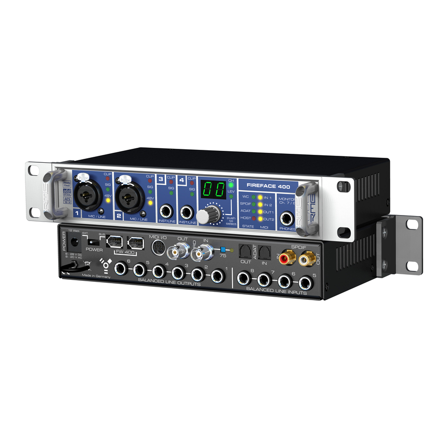
5. First Usage - Quickstart 5.1 Connectors and Front Panel The front of the Fireface 400 features instrument, microphone and line inputs, a stereo line/headphone output, a rotary encoder with 7 segment display, and several status and MIDI LEDs. The Neutrik combo jacks of the Mic/Line inputs accept the use of XLR and 1/4"... - Page 8 The rear panel of the Fireface 400 features four analog inputs, six analog outputs, the power socket, and all digital inputs and outputs. SPDIF coaxial (RCA): Fully AES/EBU compatible trans- former-coupling level adjustment. The Fireface 400 accepts commonly used digital audio formats,...
-
Page 9: Quick Start
TotalMix reach about –3 dB. The analog line inputs of the Fireface 400 can be used with +4 dBu and -10 dBV signals. The electronic input stage can handle balanced (XLR, TRS jacks) and unbalanced (TS jacks) input signals correctly. -
Page 10: Warranty
Synthax Audio AG does not accept claims for damages of any kind, especially consequential damage. Liability is limited to the value of the Fireface 400. The general terms of business drawn up by Synthax Audio AG apply at all times. - Page 11 For this the device has to be sent free to the door to: IMM Elektronik GmbH Leipziger Straße 32 D-09648 Mittweida Germany Shipments not prepaid will be rejected and returned on the original sender's costs. User's Guide Fireface 400 © RME...
- Page 12 User's Guide Fireface 400 © RME...
-
Page 13: Installation And Operation - Windows
User's Guide Fireface 400 Installation and Operation - Windows User's Guide Fireface 400 © RME... -
Page 14: Hardware Installation
RME Driver CD. Windows now installs the driver of the Fireface 400 and registers it as a new audio device in the system. After a reboot, the symbols of mixer and Settings dialog will appear in the task bar (see above). -
Page 15: Driver Update
Control Panel, Software. Click on the entry 'RME Fireface'. 10.4 Firmware Update The Flash Update Tool updates the firmware of the Fireface 400 to the latest version. It requires an already installed driver. Start the program fireface_fut.exe. The Flash Update Tool displays the current revision of the Fireface's frimware, and whether it needs an update or not. -
Page 16: Configuring The Fireface
11. Configuring the Fireface 11.1 Settings dialog - General Configuration of the Fireface 400 is done via its own settings dialog. The panel 'Settings' can be opened: • by clicking on the fire symbol in the Task Bar's system tray The mixer of the Fireface 400 (TotalMix) can be opened: •... - Page 17 SyncCheck indicates whether there is a valid signal (Lock, No Lock) for each input (Word clock, ADAT, SPDIF), or if there is a valid and synchronous signal (Sync). The AutoSync Ref display shows the input and frequency of the current sync source. See also chapter 37.1. User's Guide Fireface 400 © RME...
- Page 18 48 kHz. System Clock Shows the current clock state of the Fireface 400. The system is either Master (using its own clock) or Slave (see AutoSync Ref). Store in Flash Memory A click on this button transmits all current settings into the flash memory of the Fireface. Those settings then become active directly after power-on, and also in stand-alone operation.
-
Page 19: Settings Dialog - Input Gain
11.2 Settings dialog – Input Gain Channel 1/2 of the Fireface 400 have digitally controlled microphone preamps of the highest quality. The digital control offers a gain setting in steps of 1 dB within a range of 10 dB to 65 dB. - Page 20 – for unknown reasons. It also prevents a change from Dou- ble Speed (96 kHz) to Single Speed (48 kHz), which would cause configuration and routing problems by the changed amount of ADAT channels. User's Guide Fireface 400 © RME...
-
Page 21: Clock Modes - Synchronization
The Fireface's ADAT optical and SPDIF inputs operate simultaneously. Because there is no input selector however, the Fireface 400 has to be told which of the signals is the sync refer- ence (a digital device can only be clocked from a single source). Via Pref. Sync Ref (preferred synchronization reference) a preferred input can be defined. -
Page 22: Limit Bandwidth
More details are found in chapter 37.4. Available Settings All channels (default) activates all 18 input and output channels. Analog + SPDIF activates all 10 analog channels plus SPDIF. Analog 1-8 activates only the first eight analog channels. User's Guide Fireface 400 © RME... -
Page 23: Operation And Usage
12. Operation and Usage 12.1 Playback The Fireface 400 can play back audio data in supported formats only (sample rate, bit resolu- tion). Otherwise an error message appears (for example at 22 kHz and 8 bit). In the audio application being used, Fireface must be selected as output device. This can often be found in the Options, Preferences or Settings menus under Playback Device, Audio Devices, Audio etc. -
Page 24: Dvd-Playback (Ac-3/Dts)
AC-3/DTS capable receiver using the Fireface's SPDIF output. For this to work, the WDM* SPDIF device of the Fireface 400 has to be selected in >Control Panel/ Sounds and Multimedia/ Audio<. Also check 'use preferred device only'. -
Page 25: Low Latency Under Mme
Some motherboards with insufficient PCI bandwidth (especially older VIA based ones) suffer from crackling at settings below 512. Be sure to set the buffer size to 512 or higher in such a case (or get yourself a new motherboard…). User's Guide Fireface 400 © RME... -
Page 26: Notes On Wdm
The devices with the MME suffix bypass the Windows Kernel Mixer. This way, they achieve nearly the same performance as RME's previous (true) MME drivers. Also their behaviour (off- sets, start/stop, multi-client) is identical. So when not using GSIF or ASIO, MME should be your preferred choice. -
Page 27: Multi-Client Operation
Again the inputs can be used simultaneously. RME's sophisticated tool DIGICheck is an exception to this rule. It operates like an ASIO host, using a special technique to access playback channels already occupied. Therefore DIGICheck is able to analyse and display playback data from any software, no matter which format the software uses. -
Page 28: Digital Recording
Taking this into account, RME have included three unique features in the Fireface 400: a com- prehensive I/O signal status display showing sample frequency, lock and sync status in the Settings dialog, status LEDs for each input, and the protective Check Input function. -
Page 29: Analog Recording
Double and Quad Speed mode. A workaround is to use DDS. After having set the desired sample rate, the ASIO software recognizes the correct number of I/O channels directly when started. User's Guide Fireface 400 © RME... -
Page 30: Known Problems
Lock instead of Sync, the devices have not been set up properly! When using more than one Fireface 400, all Firefaces have to be in sync, see chapter 15. Else a periodicly repeated noise will be heared. -
Page 31: Using More Than One Fireface
15. Using more than one Fireface The current driver supports up to three Fireface 400 and 800. All units have to be in sync, i.e. have to receive valid sync information (either via word clock or by using AutoSync and feeding synchronized signals). -
Page 32: Digicheck
• Completely multi-client. Open as many measurement windows as you like, on any chan- nels and inputs or outputs! To install DIGICheck, go to the \DIGICheck directory on the RME Driver CD and run setup.exe. Follow the instructions prompted on the screen. -
Page 33: Hotline - Troubleshooting
• Check that there is a valid signal at the input. If so, the current sample frequency is dis- played in the Settings dialog. • Check whether the Fireface 400 has been selected as recording device in the audio applica- tion. -
Page 34: Installation
Hardware – Compatibility Problems. The Tech Info FireWire 800 under Windows XP SP2 in- cludes detailed information about FireWire problems after the installation of Service Pack 2. Note: both Tech Infos are not covering the Fireface 400 directly, as it has no such port. User's Guide Fireface 400 © RME... -
Page 35: Diagrams
ASIO driver have been designed to avoid conflicts in normal operation. Chan- nels 5, 6, 7 and 8 of the ADAT port have no function anymore, but are used by the hardware to transmit data at double sample rate. Record and playback are identical. User's Guide Fireface 400 © RME... -
Page 36: Channel Routing Mme 96 Khz
MME wave driver have been designed to avoid conflicts in normal operation. Channels 5, 6, 7 and 8 of the ADAT port have no function anymore, but are used by the hard- ware to transmit data at double sample rate. Record and playback are identical. User's Guide Fireface 400 © RME... - Page 37 User's Guide Fireface 400 Mac OS X – Installation and Operation User's Guide Fireface 400 © RME...
-
Page 38: Hardware Installation
20.1 Driver Installation After the Fireface has been connected, (see 19. Hardware Installation) install the drivers from the RME Driver CD. The driver files are located in the folder Fireface. Installation works auto- matically by a double-click on the file fireface.mpkg. -
Page 39: Driver Update
21. Firmware Update The Flash Update Tool updates the firmware of the Fireface 400 to the latest version. It requires an already installed driver. Start the program Fireface Flash. The Flash Update Tool displays the current revision of the Fireface's firmware, and whether it needs an update or not. -
Page 40: Configuring The Fireface
The string Errors is displayed only when transmission errors of PCI/FireWire are detected. The display will be reset on any start of a playback/record, i.e. set to zero and is thus no longer visi- ble. More information can be found in chapter 37.3. User's Guide Fireface 400 © RME... - Page 41 The word clock output signal usually equals the current sample rate. Selecting Single Speed causes the output signal to always stay within the range of 32 kHz to 48 kHz. So at 96 kHz and 192 kHz sample rate, the output word clock is 48 kHz. User's Guide Fireface 400 © RME...
- Page 42 System Clock Shows the current clock state of the Fireface 400. The unit is either Mas- ter (using its own clock) or Slave (AutoSync Ref). Limit Bandwidth Allows to reduce the amount of bandwidth used on the FireWire bus.
-
Page 43: Settings Dialog - Input Gain
22.2 Settings dialog – Input Gain Mic 1/2 Channel 1/2 of the Fireface 400 have digitally controlled microphone preamps of the highest quality. The digital control offers a gain setting in steps of 1 dB within a range of 10 dB to 65 dB. - Page 44 – for unknown reasons. It also prevents a change from Dou- ble Speed (96 kHz) to Single Speed (48 kHz), which would cause configuration and routing problems by the changed amount of ADAT channels. User's Guide Fireface 400 © RME...
-
Page 45: Clock Modes - Synchronization
The Fireface's ADAT optical and SPDIF inputs operate simultaneously. Because there is no input selector however, the Fireface 400 has to be told which of the signals is the sync refer- ence (a digital device can only be clocked from a single source). Via Pref. Sync Ref (preferred synchronization reference) a preferred input can be defined. -
Page 46: Limit Bandwidth
Thanks to its AutoSync technique and lightning fast PLLs, the Fireface 400 is not only capable of handling standard frequencies, but also any sample rate between 28 and 200 kHz. Even the... -
Page 47: Mac Os X Faq
23. Mac OS X FAQ 23.1 Round about Driver Installation The driver with the file suffix gz provided by RME is a compressed TAR archive. TAR bundles multiple files and folders into one file, but does not save memory space nor download time. -
Page 48: Supported Sample Rates
The First Aid tab to the right now allows you to check and repair disk permissions. 23.5 FireWire Compatibility RME's Fireface 400 should be fully compatible to any FireWire port found on Apple Mac com- puters. This is not true for older models like the G3 Pismo, as their FireWire controller is not OHCI compatible. -
Page 49: Hotline - Troubleshooting
• Check that there is a valid signal at the input. If so, the current sample frequency is dis- played in the Settings dialog. • Check whether the Fireface 400 has been selected as recording device in the audio applica- tion. -
Page 50: Diagram: Channel Routing At 96 Khz
8 of the ADAT port have no function anymore in Core Audio, but are used by the hardware to transmit data at double sample rate. Signal routing is identical for record and playback. User's Guide Fireface 400 © RME... -
Page 51: Stand-Alone Operation, Connections And Totalmix
User's Guide Fireface 400 Stand-Alone Operation, Connections and TotalMix User's Guide Fireface 400 © RME... -
Page 52: Stand-Alone Operation
26. Stand-alone Operation The Fireface 400 has an internal memory to permanently store all configuration data. These are: Settings dialog Sample rate, clock mode Master/Slave, configuration of the channels and the digital I/Os. TotalMix The complete mixer state. The Fireface loads those settings directly after power-on. A simple, yet useful application is to store the correct clock mode, avoiding wrong clocking and noise disturbances in a complex setup, caused by wrong synchronization. -
Page 53: 8-Channel Ad/Da-Converter
The perfect headphone monitor mixer! 26.5 Digital Format Converter As TotalMix allows for any routing of the input signals, the Fireface 400 can be used as ADAT to SPDIF converter, and SPDIF to ADAT converter. -
Page 54: Analog Inputs
27.2 Microphone / Line Front The balanced microphone inputs of the Fireface 400 offer an adjustable gain of 10 dB up to 65 dB. The soft switching, hi-current Phantom power (48 Volt) provides a professional handling of condensor mics. -
Page 55: Instrument / Line Front
27.3 Instrument / Line Front The instrument inputs 3/4 of the Fireface 400 are exceptionally flexible. Several gain and im- pedance options make them the ideal receivers for both line and instrument signals. Line Inputs 3/4 have balanced line inputs as 1/4" TRS jacks. The electronic input stage is built in a servo balanced design which handles unbalanced (mono jacks) and balanced (stereo jacks) correctly, automatically adjusting the level reference. -
Page 56: Analog Outputs
As with the analog inputs, the analog output levels are defined to maintain a problem-free op- eration with most other devices. The headroom of the Fireface 400 lies between 9 and 15 dB, according to the chosen reference level:... -
Page 57: Digital Connections
More information on Double Speed (S/MUX) can be found in chapter 37.5. ADAT In Interface for a device sending an ADAT signal to the Fireface 400. Carries the channels 1 to 8. When receiving a Double Speed signal, this input carries the channels 1 to 4. ADAT Out Interface for a device receiving an ADAT signal from the Fireface 400. -
Page 58: Midi
AC-3 digital inputs), as these decoders would otherwise not recognize the data as AC-3. 29.3 MIDI Fireface 400 offers two MIDI I/O via four 5-pin DIN jacks. The MIDI ports are added to the sys- tem by the driver. Using MIDI capable software, these ports can be accessed under the name Fireface Midi. -
Page 59: Word Clock
The signal at the BNC input can be Single, Double or Quad Speed, the Fireface 400 automatically adapts to it. As soon as a valid signal is detected, the WC LED is lit, and the Settings dialog shows either Lock or Sync (see chapter 37.1). -
Page 60: Technical Description And Background
11 MHz from a slow word clock of 44.1 kHz is no problem anymore. Additionally, jitter on the input signal is highly rejected, so that even in real world usage the re-gained clock signal is of highest quality. User's Guide Fireface 400 © RME... -
Page 61: Cables And Termination
BNC socket (see chapter 30.1). In case the Fireface 400 resides within a chain of devices receiving word clock, plug a T- adapter into its BNC input jack, and the cable supplying the word clock signal to one end of the adapter. -
Page 62: Totalmix: Routing And Monitoring
TotalMix provides the means to mix and monitor these on a single stereo output. • Mixing of the input signal to the playback signal (complete ASIO Direct Monitoring). RME not only is the pioneer of ADM, but also offers the most complete implementation of the ADM functions. - Page 63 User's Guide Fireface 400 © RME...
-
Page 64: The User Interface
The visual design of the TotalMix mixer is a result of its capability to route hardware inputs and software playback channels to any hardware output. The Fireface 400 provides 18 input chan- nels, 18 software playback channels, and 18 hardware output channels: 36 channels don't fit on the screen side by side, neither does such an arrangement provide a useful overview. -
Page 65: Elements Of A Channel
– except those of playback channel 1/2. This is correct, because as mentioned above the factory preset includes a 1:1 routing. Click on AN 3/4 and the faders above are the only active ones, same for AN5/6 and so on. User's Guide Fireface 400 © RME... - Page 66 Move the fader close to the 0 position and now press the Shift-key. This activates the fine mode, which stretches the mouse movements by a factor of 8. In this mode, a gain setting accurate to 0.1 dB is no problem at all. User's Guide Fireface 400 © RME...
-
Page 67: Submix View
As soon as one Solo button is pressed, the Solo Master button lights up in the Quick Access area. It allows to switch all selected Solos off and on again. You can comfortably make solo-groups or activate and deactivate several Solos simultaneously. User's Guide Fireface 400 © RME... -
Page 68: Quick Access Panel
Also here, RME's love for details can be seen. If any parameter is being altered after loading a preset (e. g. moving a fader), the preset display flashes in order to announce that something has been changed, still showing which state the pre- sent mix is based on. - Page 69 Menu File, Save All Presets as and Open All Presets (file suffix .fpr). After the loading the presets can be activated by the preset buttons. In case the presets have been renamed (see chapter 31.11), these names will be stored and loaded too. User's Guide Fireface 400 © RME...
-
Page 70: Monitor Panel
Note: The Mute button of the Talkback and Listenback channel is still active. Therefore it is not necessary to select <NONE>, in case one of both shall be deacti- vated. MIDI Controller, Full LC Display Support See chapter 34.4 for details. User's Guide Fireface 400 © RME... -
Page 71: Editing The Names
The preset button names are not stored in the preset files, but globally in the registry, so won't change when loading any file or saving any state as preset. But loading a preset bank (see chapter 31.8) the names will be updated. User's Guide Fireface 400 © RME... -
Page 72: Hotkeys
• Using multiple Firefaces, clicking the button Unit 2 while holding down Ctrl opens a second TotalMix window for the second Fireface 400, instead of replacing the window contents. The faders can also be moved pairwise, corresponding to the stereo-routing settings. This is achieved by pressing the Alt-key and is especially comfortable when setting the SPDIF and Phones output level. -
Page 73: Menu Options
Deactivate MIDI in Background: Disables the MIDI control as soon as another application is in the focus, or in case TotalMix has been minimized. User's Guide Fireface 400 © RME... -
Page 74: Level Meter
31.14 Level Meter The Fireface 400 calculates all the display values Peak, Over and RMS in hardware, in order to be capable of using them independent of the software in use, and to significantly reduce the CPU load. Tip: This feature, the Hardware Level Meter, is used by DIGICheck (Windows only, see chap- ter 16) to display Peak/RMS level meters of all channels, nearly without any CPU load. -
Page 75: Totalmix: The Matrix
TotalMix view, only the specific levels (max. 2) of this routing will change within the Matrix. But moving a fader in row 3 will make all vertically activated levels move at once (for example 7/8, Phones output). User's Guide Fireface 400 © RME... -
Page 76: Advantages Of The Matrix
Example: you have lowered the output level of a submix, or just a specific channel, by some dB. The audio signal passed through via ADM will be attenuated by the value set in the third row. User's Guide Fireface 400 © RME... -
Page 77: Selection And Group Based Operation
The fastest way to delete complex routings: select a channel in the mixer view, click on the menu entry Edit and select Delete. Or simply hit the Del-key. Attention: there is no undo in To- talMix, so be careful with this function! User's Guide Fireface 400 © RME... -
Page 78: Recording A Subgroup (Loopback)
A software monitor- ing on the subgroup record channels is only allowed as long as the monitoring is routed in both software and TotalMix to a different channel than the active subgroup recording one. User's Guide Fireface 400 © RME... -
Page 79: Using External Effects Devices
10 is sent by TotalMix to any output, to the Compressor, back from the Compressor to any input. This input is now selected within the record software. User's Guide Fireface 400 © RME... -
Page 80: Ms Processing
Low Cut, Expander, Compressor or Delay. The most basic application is already available di- rectly in TotalMix: Changing the level of the side channel allows to manipulate the stereo width from mono to stereo up to extended, stepless and in real-time. User's Guide Fireface 400 © RME... -
Page 81: Overview
1 - 8 select Main Monitor F10 - F12 Monitor Phones 1 - 3 *Tested with Behringer BCF2000 Firmware v1.07 in Mackie Control emulation for Steinberg mode and with Mackie Control under Mac OS X. User's Guide Fireface 400 © RME... -
Page 82: Setup
TotalMix also supports the 9th fader of the Mackie Control. This fader (labeled Master) will con- trol the stereo output faders (lowest row) which are set up as Main Monitor outputs in the Moni- tor panel. Always and only. User's Guide Fireface 400 © RME... -
Page 83: Simple Midi Control
MIDI output. As soon as it detects this special note at the input, the MIDI functionality is disabled. After fixing the loopback, check Enable MIDI Control under Options to reactivate the TotalMix MIDI. User's Guide Fireface 400 © RME... -
Page 84: Stand-Alone Midi Control
34.7 Stand-Alone MIDI Control When not connected to a computer, the Fireface 400 can be controlled directly via MIDI. To unlock the special stand-alone MIDI control mode first activate MIDI control in TotalMix (En- able MIDI control), then transfer this state via Flash current mixer state into the unit. Turning this mode off is done in the same way, but with MIDI control deactivated. - Page 85 Input channel 9 MIDI channel 10 Input channel 10 MIDI channel 11 Input channel 11 MIDI channel 12 Input channel 12 MIDI channel 13 Input channel 13 MIDI channel 14 Input channel 14 MIDI channel 15 User's Guide Fireface 400 © RME...
- Page 86 User's Guide Fireface 400 © RME...
-
Page 87: Technical Reference
User's Guide Fireface 400 Technical Reference User's Guide Fireface 400 © RME... -
Page 88: Tech Info
35. TECH INFO Not all information to and around our products fit in a manual. Therefore RME offers a lot more and detailed information in the Tech Infos. The very latest Tech Infos can be found on our website, section News & Infos, or the directory \rmeaudio.web\techinfo on the RME Driver CD. -
Page 89: Technical Specifications
• Output level switchable Hi Gain, +4 dBu, -10 dBV • Output level at 0 dBFS @ Hi Gain: +19 dBu • Output level at 0 dBFS @ +4 dBu: +13 dBu • Output level at 0 dBFS @ -10 dBV: +2 dBV User's Guide Fireface 400 © RME... -
Page 90: Midi
• Level range: 1.0 Vpp – 5.6 Vpp • Lock Range: 27 kHz – 200 kHz • Jitter when synced to input signal: < 1 ns • Jitter suppression: > 30 dB (2.4 kHz) User's Guide Fireface 400 © RME... -
Page 91: Digital Outputs
• Temperature range: +5° up to +50° Celsius (41° F up to 122°F) • Relative humidity: < 75%, non condensing • Included power supply: Internal switching PSU, 100 - 240 V AC, 2 A, 24 Watts User's Guide Fireface 400 © RME... -
Page 92: Technical Background
PLL tracks the receiver's frequency. If an ADAT or SPDIF signal is applied to the Fireface 400, the corresponding input LED starts flashing. The unit indicates LOCK, i. e. a valid input signal (in case the signal is also in sync, the LED is constantly lit, see below). -
Page 93: Latency And Monitoring
RME's Zero Latency Monitoring. The term describes the digital path of the audio data from the input of the interface to its output. The digital receiver of the Fireface 400 can't operate un-buffered, and together with TotalMix and the output via the transmitter, it causes a typical delay of 3 samples. -
Page 94: Firewire Audio
PCI cards, the FireWire subsystem creates an additional CPU load at lower latencies. One Fireface 400 can achieve a performance similar to a PCI card with an optimal PC. An 'op- timal' PC has an undisturbed PCI bus. Intel's motherboard D875PBZ e.g., has network, PATA and SATA connected directly to the chipset. -
Page 95: Number Of Channels And Bus Load
PCI bus - causes drop outs. Transferring these experiences to FireWire and the Fireface 400 means that besides the num- ber of channels the bus load has to be taken into account too. One channel at 96 kHz causes... -
Page 96: Ds - Double Speed
37.5 DS - Double Speed When activating the Double Speed mode the Fireface 400 operates at double sample rate. The internal clock 44.1 kHz turns to 88.2 kHz, 48 kHz to 96 kHz. The internal resolution is still 24 bit. -
Page 97: Aes/Ebu - Spdif
The table shows that a Professional-coded signal would lead to malfunctions for copy prohibi- tion and emphasis, if being read as Consumer-coded data. Nowadays many devices with SPDIF input can handle Professional subcode. Devices with AES3 input almost always accept Consumer SPDIF (passive cable adapter necessary). User's Guide Fireface 400 © RME... -
Page 98: Noise Level In Ds / Qs Mode
When limiting the measurement's frequency range to 22 kHz (audio bandpass, weighted) the value would be -110 dB again. This can be verified even with RME's Windows tool DIGICheck. Although a dBA weighted value does not include such a strong bandwidth limitation as audio bandpass does, the displayed value of –108 dB is nearly identical to the one at 48 kHz. -
Page 99: Diagrams
38. Diagrams 38.1 Block Diagram Fireface 400 User's Guide Fireface 400 © RME... -
Page 100: Connector Pinouts
TRS plug to TS plugs is required. The pin assignment follows interna- tional standards. The left channel is connected to the tip, the right channel to the ring of the TRS jack/plug. User's Guide Fireface 400 © RME...
Need help?
Do you have a question about the Fireface 400 and is the answer not in the manual?
Questions and answers