Table of Contents
Advertisement
Instruction Manual
D103272X012
Fisher
LCP100 Local Control Panel
™
Contents
Introduction
. . . . . . . . . . . . . . . . . . . . . . . . . . . . . . . . .
Scope of Manual
. . . . . . . . . . . . . . . . . . . . . . . . . . . . .
. . . . . . . . . . . . . . . . . . . . . . . . . . . . . . . . .
. . . . . . . . . . . . . . . . . . . . . . . . . . . . . . .
. . . . . . . . . . . . . . . . . . . . . . . . . . .
. . . . . . . . . . . . . . . . . . . . . . . . . . . . . . . . . .
Instructions for "Safe Use" and Installation
in Hazardous Areas
. . . . . . . . . . . . . . . . . . . . . . . . . . . . . . . . . .
. . . . . . . . . . . . . . . . . . . . . . . . . . . .
. . . . . . . . . . . . . . . . . . . . . . . . . . . . . . . . . . . . . .
. . . . . . . . . . . . . . . . . . . . . . . .
. . . . . . . . . . . . . . . . . . . . . . . . . . . . . . . .
. . . . . . . . . . . . . . . . . . . . . . . . . . . .
. . . . . . . . . . . . . . . . . . . . . . . . . . . . . . .
. . . . . . . . . . . . . . . . . . . . . . . . . . . . . . . . . . .
. . . . . . . . . . . . . . . . . . . . . . . . . . . . .
Introduction
Scope of Manual
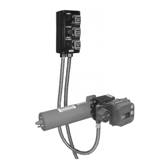
This instruction manual includes installation and maintenance information for the Fisher LCP100 local control panel
(figure 1). This device is used with Fisher FIELDVUE™ instruments in Safety Instrumented Systems (SIS). Refer to the
DVC6200 SIS Digital Valve Controllers for Safety Instrumented System (SIS) Solutions instruction manual
(D103557X012) or the DVC6000 SIS Digital Valve Controllers for Safety Instrumented System (SIS) Solutions
instruction manual (D103230X012) for additional information.
Unless otherwise noted, the information in this instruction manual applies to both DVC6200 SIS and DVC6000 SIS
digital valve controllers. For simplicity, the DVC6200 SIS model name will be used throughout.
www.Fisher.com
. . . . . . . . . . . . . . . . . . . . . . . .
. . . . . . . . . . . . . . . . . . . . . . . .
Figure 1. Fisher LCP100 Local Control Panel, with
FIELDVUE DVC6200 SIS Digital Valve Controller
1
and Bettis
™
Actuator
1
2
2
2
5
5
5
5
24
25
25
26
26
27
27
27
X0247
LCP100 Local Control Panel
August 2017
Advertisement
Table of Contents

Related Manuals for Emerson Fisher LCP100


Summary of Contents for Emerson Fisher LCP100
-
Page 1: Table Of Contents
Introduction Scope of Manual This instruction manual includes installation and maintenance information for the Fisher LCP100 local control panel (figure 1). This device is used with Fisher FIELDVUE™ instruments in Safety Instrumented Systems (SIS). Refer to the DVC6200 SIS Digital Valve Controllers for Safety Instrumented System (SIS) Solutions instruction manual (D103557X012) or the DVC6000 SIS Digital Valve Controllers for Safety Instrumented System (SIS) Solutions instruction manual (D103230X012) for additional information. -
Page 2: Description
To avoid personal injury or property damage, it is important to carefully read, understand, and follow all of the contents of this manual, includingall safety cautions and warnings. If you have any questions about these instructions, contact your Emerson sales office or Local Business Partner. - Page 3 Instruction Manual LCP100 Local Control Panel D103272X012 August 2017 Table 1. Specifications Power Options (switch selectable) Electrical Housing IP66 External: 24 VDC +/- 10% @ 50 mA maximum continuous current (100 mA maximum inrush) Electromagnetic Interference (EMI) Loop: 8‐20 mA (LCP100 and DVC6200 SIS combined) Meets EN 61326-1:2013 Immunity—Industrial locations per Table 2 of...
- Page 4 150 kHz to 80 MHz at 3 Vrms with 1 kHz AM at 80% Specification limit = ±1% of span 1. A = No degradation during testing. B = Temporary degradation during testing, but is self‐recovering. Figure 2. Fisher LCP100 Local Control Panel Dimensions (7.6) (10.1) (3.7)
-
Page 5: Installation
D ATEX Hazardous Area Approvals - DVC2000 Digital Valve Controllers (D104237X012) D IECEx Hazardous Area Approvals - DVC2000 Digital Valve Controllers (D104238X012) All documents are available from your Emerson sales office, Local Business Partner, or Fisher.com. Contact your Emerson sales office or Local Business Partner for all other approval/certification information. - Page 6 Instruction Manual LCP100 Local Control Panel August 2017 D103272X012 Table 3. Wiring Configurations with DVC6200 SIS Digital Valve Controller Wiring Order from DVC6200 SIS Mode LCP100 Protection Method LCP100 Power Source Refer to figure Logic Solver (Current or Voltage) Point-to-Point DVC6200 SIS then LCP100 Multi-Drop LOOP...
- Page 7 Instruction Manual LCP100 Local Control Panel D103272X012 August 2017 Figure 4. Interior Details of Fisher LCP100 and FIELDVUE DVC6200 SIS POWER SELECTOR SWITCH (FACTORY LABEL IDENTIFIES TERMINALS USED WHEN POWER DEFAULT IS 24VDC) SELECTOR SWITCH IS SET TO 24VDC. NOTE THAT...
- Page 8 Instruction Manual LCP100 Local Control Panel August 2017 D103272X012 Figure 5. Ex e mb [ib] IIC or Ex tb IIIC Wiring Diagram 1 LCP100 LCP100 Wiring Order from DVC6200 SIS Mode Protection Method Power Source Logic Solver (Current or Voltage) Ex e mb [ib] IIC LOOP DVC6200 SIS then LCP100...
- Page 9 Instruction Manual LCP100 Local Control Panel D103272X012 August 2017 Figure 6. Ex e mb [ib] IIC or Ex tb IIIC Wiring Diagram 2 LCP100 LCP100 Wiring Order from DVC6200 SIS Mode Protection Method Power Source Logic Solver (Current or Voltage) Ex e mb [ib] IIC LOOP DVC6200 SIS then LCP100...
- Page 10 Instruction Manual LCP100 Local Control Panel August 2017 D103272X012 Figure 7. Ex e mb [ib] IIC or Ex tb IIIC Wiring Diagram 3 LCP100 LCP100 Wiring Order from DVC6200 SIS Mode Protection Method Power Source Logic Solver (Current or Voltage) Ex e mb [ib] IIC LOOP LCP100 then DVC6200 SIS...
- Page 11 Instruction Manual LCP100 Local Control Panel D103272X012 August 2017 Figure 8. Ex e mb [ib] IIC or Ex tb IIIC Wiring Diagram 4 LCP100 LCP100 Wiring Order from DVC6200 SIS Mode Protection Method Power Source Logic Solver (Current or Voltage) Ex e mb [ib] IIC LOOP LCP100 then DVC6200 SIS...
- Page 12 Instruction Manual LCP100 Local Control Panel August 2017 D103272X012 Figure 9. Ex e mb [ib] IIC or Ex tb IIIC Wiring Diagram 5 LCP100 LCP100 Wiring Order from DVC6200 SIS Mode Protection Method Power Source Logic Solver (Current or Voltage) Ex e mb [ib] IIC 24VDC DVC6200 SIS then LCP100...
- Page 13 Instruction Manual LCP100 Local Control Panel D103272X012 August 2017 Figure 10. Ex e mb [ib] IIC or Ex tb IIIC Wiring Diagram 6 LCP100 LCP100 Wiring Order from DVC6200 SIS Mode Protection Method Power Source Logic Solver (Current or Voltage) Ex e mb [ib] IIC 24VDC DVC6200 SIS then LCP100...
- Page 14 Instruction Manual LCP100 Local Control Panel August 2017 D103272X012 Figure 11. Ex ic IIC or Ex tb IIIC Wiring Diagram 1 LCP100 LCP100 Wiring Order from DVC6200 SIS Mode Protection Method Power Source Logic Solver (Current or Voltage) Ex ic IIC LOOP DVC6200 SIS then LCP100 Point-to-Point...
- Page 15 Instruction Manual LCP100 Local Control Panel D103272X012 August 2017 Figure 12. Ex ic IIC or Ex tb IIIC Wiring Diagram 2 LCP100 LCP100 Wiring Order from DVC6200 SIS Mode Protection Method Power Source Logic Solver (Current or Voltage) Ex ic IIC LOOP DVC6200 SIS then LCP100 Multi-Drop...
- Page 16 Instruction Manual LCP100 Local Control Panel August 2017 D103272X012 Figure 13. Ex ic IIC or Ex tb IIIC Wiring Diagram 3 LCP100 LCP100 Wiring Order from DVC6200 SIS Mode Protection Method Power Source Logic Solver (Current or Voltage) Ex ic IIC LOOP LCP100 then DVC6200 SIS Point-to-Point...
- Page 17 Instruction Manual LCP100 Local Control Panel D103272X012 August 2017 Figure 14. Ex ic IIC or Ex tb IIIC Wiring Diagram 4 LCP100 LCP100 Wiring Order from DVC6200 SIS Mode Protection Method Power Source Logic Solver (Current or Voltage) Ex ic IIC LOOP LCP100 then DVC6200 SIS Multi-Drop...
- Page 18 Instruction Manual LCP100 Local Control Panel August 2017 D103272X012 Figure 15. Ex ic IIC or Ex tb IIIC Wiring Diagram 5 LCP100 LCP100 Wiring Order from DVC6200 SIS Mode Protection Method Power Source Logic Solver (Current or Voltage) Ex ic IIC 24VDC DVC6200 SIS then LCP100 Point-to-Point...
- Page 19 Instruction Manual LCP100 Local Control Panel D103272X012 August 2017 Figure 16. Ex ic IIC or Ex tb IIIC Wiring Diagram 6 LCP100 LCP100 Wiring Order from DVC6200 SIS Mode Protection Method Power Source Logic Solver (Current or Voltage) Ex ic IIC 24VDC DVC6200 SIS then LCP100 Multi-Drop...
- Page 20 Instruction Manual LCP100 Local Control Panel August 2017 D103272X012 Figure 17. Ex ia IIB or Ex tb IIIC Wiring Diagram 1 LCP100 LCP100 Wiring Order from DVC6200 SIS Mode Protection Method Power Source Logic Solver (Current or Voltage) Ex ia IIB LOOP DVC6200 SIS then LCP100 Point-to-Point...
- Page 21 Instruction Manual LCP100 Local Control Panel D103272X012 August 2017 Figure 18. Ex ia IIB or Ex tb IIIC Wiring Diagram 2 LCP100 LCP100 Wiring Order from DVC6200 SIS Mode Protection Method Power Source Logic Solver (Current or Voltage) Ex ia IIB LOOP DVC6200 SIS then LCP100 Multi-Drop...
- Page 22 Instruction Manual LCP100 Local Control Panel August 2017 D103272X012 Figure 19. Ex ia IIB or Ex tb IIIC Wiring Diagram 3 LCP100 LCP100 Wiring Order from DVC6200 SIS Mode Protection Method Power Source Logic Solver (Current or Voltage) Ex ia IIB LOOP LCP100 then DVC6200 SIS Point-to-Point...
- Page 23 Instruction Manual LCP100 Local Control Panel D103272X012 August 2017 Figure 20. Ex ia IIB or Ex tb IIIC Wiring Diagram 4 LCP100 LCP100 Wiring Order from DVC6200 SIS Mode Protection Method Power Source Logic Solver (Current or Voltage) Ex ia IIB LOOP LCP100 then DVC6200 SIS Multi-Drop...
-
Page 24: Pre-Setup Testing
Instruction Manual LCP100 Local Control Panel August 2017 D103272X012 Pre‐Setup Testing Before connecting the LCP100 to the process, conduct the following tests on the LCP100 connected to the DVC6200 SIS. Successful Partial Stroke Test 1. Press the Valve Test (bottom) pushbutton for more than 3 seconds (but less than 10 seconds). 2. -
Page 25: Setup
Instruction Manual LCP100 Local Control Panel D103272X012 August 2017 Setup In order for the LCP100 to operate properly, it must be connected to a DVC6200 SIS with firmware revision 3 or later, or a DVC6000 SIS device with firmware revision 7 or later. Once the physical connections are made, use the following checklist to configure the LCP100. -
Page 26: Maintenance
Instruction Manual LCP100 Local Control Panel August 2017 D103272X012 Table 4. Fisher LCP100 Light and Button Operation PRESS INDICATED BUTTON TO... WHAT THE LCP100 LIGHTS SHOW... POSSIBLE CONDITIONS... Middle Bottom Solid The valve is in its normal operating state. - - -... -
Page 27: Parts Ordering
Use only genuine Fisher replacement parts. Components that are not supplied by Emerson Automation Solutions should not, under any circumstances, be used in any Fisher instrument. Use of components not supplied by Emerson Automation Solutions may void your warranty and hazardous area approval, might adversely affect the performance of the instrument, and could cause personal injury and property damage. - Page 28 Responsibility for proper selection, use, and maintenance of any product remains solely with the purchaser and end user. Fisher, FIELDVUE, and Bettis are marks owned by one of the companies in the Emerson Automation Solutions business unit of Emerson Electric Co. Emerson Automation Solutions, Emerson, and the Emerson logo are trademarks and service marks of Emerson Electric Co.
Need help?
Do you have a question about the Fisher LCP100 and is the answer not in the manual?
Questions and answers