Table of Contents
Advertisement
Quick Links
Installation Instructions and Operator Manual for the
Appleton™ PlexPower™ Fiber Panelboard
FOR PROPER AND SAFE INSTALLATION OF THIS PRODUCT, PLEASE READ AND RETAIN THE FOLLOWING INSTRUCTIONS.
Applications
The PlexPower™ Fiber Panelboard provides control
of electrical circuits and communications patch panels
in hazardous environments such as:
• Petroleum plants
• Chemical plants
• Refineries
• Wastewater treatment plants
• Paper and pulp industries
• Other process facilities
Product Safety
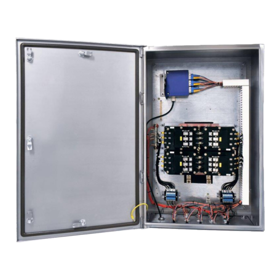
PlexPower Fiber Panelboard with Belden Fiber Patch Panel having 1,2,3 or 4 Single Module in place.
Signal Words Defined
DANGER:
Indicates a hazardous situation which, if not avoided, will result in death or serious injury.
which, if not avoided, could result in death or serious injury.
NOTICE:
moderate injury.
Is used to address practices not related to physical injury.
Safety Instructions
WARNING:
Before replacing any part or accessory of the panel, ensure that the power to panel Mains is Switched OFF.
CAUTION:
Live parts behind the cover; only authorized person to open.
NOTICE:
For Internally Actuated Panel, a Dead Front Plate is supplied to ensure safe operation which will protect operators from electrocution.
Appleton • 1.800.621.1506 • www.appletonelec.com
504483-000 INSTRUCTION SHEET
CAUTION:
Indicates a hazardous situation which, if not avoided, could result in minor or
WARNING:
Indicates a hazardous situation
504483-000 Rev. B 10/08/18 • Page 1 of 16
Advertisement
Table of Contents

Related Manuals for Emerson Appleton PlexPower


Summary of Contents for Emerson Appleton PlexPower
- Page 1 504483-000 INSTRUCTION SHEET Installation Instructions and Operator Manual for the Appleton™ PlexPower™ Fiber Panelboard FOR PROPER AND SAFE INSTALLATION OF THIS PRODUCT, PLEASE READ AND RETAIN THE FOLLOWING INSTRUCTIONS. Applications The PlexPower™ Fiber Panelboard provides control of electrical circuits and communications patch panels in hazardous environments such as: •...
-
Page 2: Installation
Installation FIGURE 1 - PlexPower Fiber Panel Assembly (QC) External Actuation - Approx. Weight: 90 kg FIGURE 2 - FIGURE 1 - PlexPower Fiber Panel Assembly (QC) Internal Actuation - Approx. Weight: 85 kg Appleton • 1.800.621.1506 • www.appletonelec.com 504483-000 Rev. B 10/08/18 • Page 2 of 16... -
Page 3: Owner's Responsibility
Owner’s Responsibility: • All installation instructions need to be followed. • Users need to follow latest edition of the National Electrical Code or the Canadian Electrical Code for installation guidelines. ® • Inspect the panelboard thoroughly before operating. • Understand how to operate all standard and accessory equipment. •... - Page 4 Lifting & Moving Panel by Using Forklift Truck Follow the instructions/procedure below to transfer the panel from one location to another by using forklift. • Keep the panelboard vertical on a stand/pallet from which we can lift it and transfer to desired location. Transfer of panel with fork- lift without using any pallet or stand could damage Gland plate provided on panel bottom.
- Page 5 Mounting: • Ensure mounting studs/bolts are in place on mounting frame, mounting strut, wall etc. according to dimensions specified on the drawings included in Figures 1 and • The panelboard is intended to be mounted vertically. Use mounting feet U-Slot for positioning and fastening panelboard. •...
-
Page 6: Mounting Procedure
Mounting Procedure: • After both bottom and middle mounting feet are fixed, remove the eye bolt from top mounting foot and fix it with M10 bolt. • Make sure that all the bolts are fully tight. • The number of bolts required to mount the panel should be equal to the number of mounting feet of panel. •... -
Page 7: Electrical Connections
Electrical Connections: To open the panelboard's cover for wiring, unlock the latches on the panelboard using a screwdriver. Incoming supply can be wired to line side of QC housing (Figure 7). Load side connections are hard-wired (customer wiring). Main ground lug is provided for system ground. FIGURE 7 - PlexPower Fiber Panel Assembly Appleton •... - Page 8 Wiring Connections for Customer Input and Output Incoming and outgoing connection to panel: • To facilitate cable connections to line of panel and to take out cables towards load from power terminal blocks, user needs to drill holes on gland plate provided on bottom of enclosure. •...
-
Page 9: Wiring Diagram
Wiring Diagram To connect cables from load to panelboard power terminal blocks, refer below wiring diagram and terminal block marking. FIGURE 11 Appleton • 1.800.621.1506 • www.appletonelec.com 504483-000 Rev. B 10/08/18 • Page 9 of 16... -
Page 10: Electrical Testing
Wire Sizing Chart For Breaker- Reference - CSA C22.2, NO. 5-02, Table 6.1.4.2.1, UL 489. TABLE 1 Current (AMPS) Required WIRE SIZE 15A OR LESS 14 AWG 12 AWG MINIMUM 25A-30A 10 AWG MINIMUM 40A-50A 8 AWG MINIMUM 6 AWG MINIMUM Terminals - Connection Devices TABLE 2 Purpose... -
Page 11: Operation
Operation Branch Breaker The Status of the branch breaker is determined by position of knob as indicated by the label. Operation is as simple as twisting the handle to the desired position. FIGURE 12 Appleton • 1.800.621.1506 • www.appletonelec.com 504483-000 Rev. B 10/08/18 • Page 11 of 16... - Page 12 Split Type Dead Front: By using a split type dead front arrangement a user can access power and data transmission parts separately inside a panel. FIGURE 13 Appleton • 1.800.621.1506 • www.appletonelec.com 504483-000 Rev. B 10/08/18 • Page 12 of 16...
-
Page 13: General Maintenance
General Maintenance Maintenance: 1. Before carrying out any work on equipment, cited safety instructions must be very carefully observed (DO NOT OPEN WITH POWER “ON”). 2. Incoming power should be locked and tagged out for safety while in maintenance. 3. The hardware installed shall be inspected on regular schedule. 4. - Page 14 Replacement Of Fiber Module: • Remove all Fiber optics cable from Fiber Module. • Remove Fiber module from the Din Rail. • Replace module with (LC, SC or ST type) as per requirement. • Reinstall Fiber Module in Din Rail. FIGURE 14 - ST Type Fiber Module Appleton •...
- Page 15 Replacement Of Fuses 1. Check continuity of fuse, if it is damaged, replace fuse. 2. Open fuse holder cap as shown in below sequence of images. 3. Then remove Fuse from Fuse holder body. 4. Install new Fuse into the Fuse Holder 5.
- Page 16 While every precaution has been taken to ensure accuracy and completeness in this manual, Appleton Grp, LLC. assumes no responsibility, and disclaims all liability for damages resulting from use of this information or for any errors or omissions. Specifications are subject to change without notice. The Appleton and Emerson logos are registered in the U.S. Patent and Trademark Office. All other product or service names are the property of their registered owners.
Need help?
Do you have a question about the Appleton PlexPower and is the answer not in the manual?
Questions and answers