Siemens ET 200SP HA Manual
Interface, im 155-6 pn ha
Hide thumbs
Also See for ET 200SP HA:
- User manual ,
- System manual (186 pages) ,
- Compact operating instructions (182 pages)
Table of Contents
Advertisement
Advertisement
Table of Contents

Subscribe to Our Youtube Channel
Related Manuals for Siemens ET 200SP HA


Summary of Contents for Siemens ET 200SP HA
- Page 1 Security information Product overview Wiring SIMATIC Parameters ET 200SP HA Interface Module IM 155-6 PN HA Maintenance (6DL1155-6AU00-0PM0) Displays and interrupts Manual Technical specifications Diagnostic messages 05/2017 A5E39262148-AA...
- Page 2 Note the following: WARNING Siemens products may only be used for the applications described in the catalog and in the relevant technical documentation. If products and components from other manufacturers are used, these must be recommended or approved by Siemens. Proper transport, storage, installation, assembly, commissioning, operation and maintenance are required to ensure that the products operate safely and without any problems.
-
Page 3: Table Of Contents
Table of contents Security information............................5 Product overview............................7 Properties..........................7 Wiring.................................11 Pin assignment........................11 Schematic circuit diagram......................13 Parameters..............................15 Parameter assignment......................15 Maintenance...............................17 Exchanging the BusAdapter or interface of the distributed I/O..........17 Displays and interrupts..........................19 Status and error displays.......................19 Interrupts..........................23 Technical specifications..........................25 Diagnostic messages..........................31 Diagnostics messages and maintenance events..............31 Interface Module IM 155-6 PN HA (6DL1155-6AU00-0PM0) Manual, 05/2017, A5E39262148-AA... - Page 4 Table of contents Interface Module IM 155-6 PN HA (6DL1155-6AU00-0PM0) Manual, 05/2017, A5E39262148-AA...
-
Page 5: Security Information
In order to protect plants, systems, machines and networks against cyber threats, it is necessary to implement – and continuously maintain – a holistic, state-of-the-art industrial security concept. Siemens’ products and solutions only form one element of such a concept. Customer is responsible to prevent unauthorized access to its plants, systems, machines and networks. - Page 6 Security information Interface Module IM 155-6 PN HA (6DL1155-6AU00-0PM0) Manual, 05/2017, A5E39262148-AA...
-
Page 7: Product Overview
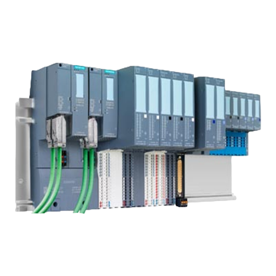
The IM 155‑6 PN HA, together with the carrier and BusAdapter, forms the interface of the ET 200SP HA. The interface is used for communication between the CPU and the connected ET 200SP HA I/O modules via PROFINET IO. Interface Module IM 155-6 PN HA (6DL1155-6AU00-0PM0) - Page 8 Product overview 2.1 Properties The interface has the following technical properties: ● Supply voltage 1L+ 24 V DC (SELV/PELV). The supply voltage is fed via the carrier module. The connection plug is included in the scope of delivery of the interface module. ●...
- Page 9 ● The server module and power bus cover are included in the product package of the carrier module and are available separately as accessories. ● The server module and power bus cover terminate the configuration of the ET 200SP HA. ● Place the server module and the power bus cover at the end of the configuration.
- Page 10 Product overview 2.1 Properties Interface Module IM 155-6 PN HA (6DL1155-6AU00-0PM0) Manual, 05/2017, A5E39262148-AA...
-
Page 11: Wiring
Wiring Pin assignment 24 V DC supply voltage The following table shows the signal names and the descriptions of the pin assignment for a 24 V DC supply voltage. Table 3-1 Pin assignment 24 V DC supply voltage View Signal name Description Plug IM connection... - Page 12 Wiring 3.1 Pin assignment PROFINET IO with BusAdapter BA 2×FC The following table shows the signal name and designation of the pin assignment of the BusAdapter BA 2×FC. Table 3-3 Pin assignment of PROFINET IO with BusAdapter BA 2×FC View Signal name Description Transmit data +...
-
Page 13: Schematic Circuit Diagram
Wiring 3.2 Schematic circuit diagram Schematic circuit diagram Schematic circuit diagram The following figure shows the block diagram of the IM 155‑6 PN HA interface module. ① Switch Supply voltage (24 V DC) ② Backplane bus connection and electronics Ground ③... - Page 14 Wiring 3.2 Schematic circuit diagram Interface Module IM 155-6 PN HA (6DL1155-6AU00-0PM0) Manual, 05/2017, A5E39262148-AA...
-
Page 15: Parameters
Parameters Parameter assignment Configuring You configure the ET 200SP HA on a CPU 410 as of FW V8.2. Parameters The parameter assignment specifies the properties of the IO device. Additional information You can find information on basic procedures and available settings in the following documentation: ●... - Page 16 Parameters 4.1 Parameter assignment Interface Module IM 155-6 PN HA (6DL1155-6AU00-0PM0) Manual, 05/2017, A5E39262148-AA...
-
Page 17: Maintenance
BusAdapter to the interface. Note Restoring the factory settings Not possible for ET 200SP HA: The reset to factory settings deletes the device name in the interface and in the BusAdapter. Avoiding deleting of the device name in the BusAdapter: Proceed as follows: 1. - Page 18 Maintenance 5.1 Exchanging the BusAdapter or interface of the distributed I/O Interface Module IM 155-6 PN HA (6DL1155-6AU00-0PM0) Manual, 05/2017, A5E39262148-AA...
-
Page 19: Displays And Interrupts
Displays and interrupts Status and error displays LED displays The status and error displays of the IM 155-6 PN HA are shown in the figure below. SIEMENS ① RN LED (green) ② ER LED (red) ③ MT LED (yellow) ④... - Page 20 Configure the interface module with the configuration software. ET 200SP HA starts up. ET 200SP HA parameters are assigned ET 200SP HA is exchanging data with the IO Control‐ ler. ER LED Table 6-2 Error displays of the ER LED...
- Page 21 Displays and interrupts 6.1 Status and error displays MT LED Table 6-3 Maintenance display of the MT LED MT LED Meaning Maintenance is not required. Maintenance is required, meaning that at least one maintenance event has occurred. ACT LED Table 6-4 Status display of the ACT LED ACT LED Meaning (only relevant for IO device with redundant IM)
- Page 22 Error type Cause of error Solution (MAINT) Check the configuration of the ● No server module ET 200SP HA. ● Interruptions on the backplane bus ● Short-circuit on backplane bus Interface Module IM 155-6 PN HA (6DL1155-6AU00-0PM0) Manual, 05/2017, A5E39262148-AA...
-
Page 23: Interrupts
Displays and interrupts 6.2 Interrupts Note The following LEDs indicate a short-circuit in the backplane bus supply or in the bus connection supply: ● LED PWR: On ● LED RN, ER and MT: Off Interrupts Diagnostics interrupts Diagnostic interrupts are used by the IM 155-6 PN HA to signal diagnostic messages as well as maintenance events, see also appendix Diagnostics messages and maintenance events (Page 31) The IM 155-6 PN HA generates a diagnostic interrupt for the following events:... - Page 24 Displays and interrupts 6.2 Interrupts Interface Module IM 155-6 PN HA (6DL1155-6AU00-0PM0) Manual, 05/2017, A5E39262148-AA...
-
Page 25: Technical Specifications
Technical specifications Article number 6DL1155-6AU00-0PM0 General information Product type designation IM 155-6 PN HW functional status FS01 Firmware version V1.0 Vendor identification (VendorID) 02AH Device identifier (DeviceID) 030FH Product function Yes; I&M0 to I&M3 ● I&M data Engineering with V9.0 ●... - Page 26 Technical specifications Article number 6DL1155-6AU00-0PM0 Rack 56; 56 slots for I/O modules + server module (width ● Modules per rack, max. without IM ≤ 1.3 m) Time stamping Accuracy 1 ms; In compliance with the supplementary con‐ ditions described in the Equipment Manual Interfaces Number of PROFINET interfaces 1;...
- Page 27 Technical specifications Article number 6DL1155-6AU00-0PM0 Yes; Green LED ● ACTIVE-LED (active IM in redundant configuration) ● Monitoring of the supply voltage (PWR-LED) Yes; green PWR LED Yes; 2x green link LEDs on BusAdapter ● Connection display LINK TX/RX Potential separation between PROFINET and all other circuits Yes;...
- Page 28 Technical specifications Article number 6DL1193-6AR00-0AA0 Interfaces Number of PROFINET interfaces 1; 2 ports (switch) RJ45 PROFINET IO Yes; 2x RJ45 ● RJ 45 Cable length 100 m – Cu conductors Ambient conditions Ambient temperature during operation -40 °C ● min. 70 °C ●...
- Page 29 Technical specifications Article number 6DL1193-6AF00-0AA0 Interfaces Number of PROFINET interfaces 1; 2 ports (switch) FC PROFINET IO Yes; 2 x ● FC (FastConnect) Cable length 100 m – Cu conductors Ambient conditions Ambient temperature during operation -40 °C ● min. 70 °C ●...
- Page 30 Technical specifications Interface Module IM 155-6 PN HA (6DL1155-6AU00-0PM0) Manual, 05/2017, A5E39262148-AA...
-
Page 31: Diagnostic Messages
No server module was present Verify that the server mod‐ Station Stop – No tion during power-up of an ule is correctly installed in server module ET 200SP HA station. the rack. Configuration error: 0x0602 0x0691 Configura‐ The installed terminal block Ensure that a matching ter‐... - Page 32 Diagnostic messages A.1 Diagnostics messages and maintenance events Diagnostics message Channel Extended Assignment Meaning Remedy error type channel (CET) error type (CET) Redundancy error: 0x0630 0x06D0 Redundant Errors in the redundancy of the Replace the partner inter‐ Failure in the partner modules interface module are signaled.
Need help?
Do you have a question about the ET 200SP HA and is the answer not in the manual?
Questions and answers