Siemens SIMATIC ET 200SP HA, SIMATIC DI 16x24VDC NPN Manual
- System manual (186 pages) ,
- Compact operating instructions (182 pages) ,
- Original instructions manual (165 pages)
Advertisement
- 1 Warning notice system
- 2 Preface
- 3 Scannable code on the product
- 4 Product overview
- 5 Terminal
- 6 Parameters
- 7 Displays and interrupts
- 8 Technical specifications
- 9 Drivers/parameters/diagnostics messages and address space
- 10 Documents / Resources
Warning notice system
This manual contains notices you have to observe in order to ensure your personal safety, as well as to prevent damage to property. The notices referring to your personal safety are highlighted in the manual by a safety alert symbol, notices referring only to property damage have no safety alert symbol. These notices shown below are graded according to the degree of danger.

indicates that death or severe personal injury will result if proper precautions are not taken.

indicates that death or severe personal injury may result if proper precautions are not taken.

indicates that minor personal injury can result if proper precautions are not taken.
NOTICE
indicates that property damage can result if proper precautions are not taken.
If more than one degree of danger is present, the warning notice representing the highest degree of danger will be used. A notice warning of injury to persons with a safety alert symbol may also include a warning relating to property damage.
Preface
Validity of the documentation
This manual describes the following I/O module:
| System family | I/O module | Article number |
| SIMATIC Distributed I/O System ET 200SP HA | DI 16x24VDC NPN | 6DL1131-6BH60-0PH1 |
It complements the system manual of the ET 200SP HA Distributed I/O System.
Functions that generally relate to the system are described in this manual.
The information in this device manual and the system/function manuals enables you to put the ET 200SP HA into operation.
Conventions
Please also observe notes marked as follows:
Note
A note contains important information on the product described in the documentation, on the handling of the product or on the section of the documentation to which particular attention should be paid.
Scannable code on the product
Scannable code on the product
You can find information on the scannable code on the product in the ET 200SP HA System Manual: ET 200SP HA System Manual | SIOS (https://support.industry.siemens.com/cs/ww/en/view/109817158)
Product overview
I/O module
Definition
The DI 16x24VDC NPN I/O module is a digital input module with 16 power inputs for process control.
In addition to the technical specifications, this module has the following properties:
- Sourcing input (NPN, M-reading)
- Module-specific configurable diagnostics for missing supply voltage L+
- Suitable for connecting switches and 2-/3-wire sensors according to IEC 61131, types 1 and 3
Digital inputs with the following parameterizable properties:
- Diagnostics
- Input delay
- Hardware interrupts for positive and negative edges
The I/O module supports the following functions:
- Firmware update
- I&M identification data
- Parameter reassignment in RUN
- Value status QI
You can configure the I/O module with HW Config and integrate it into your system.
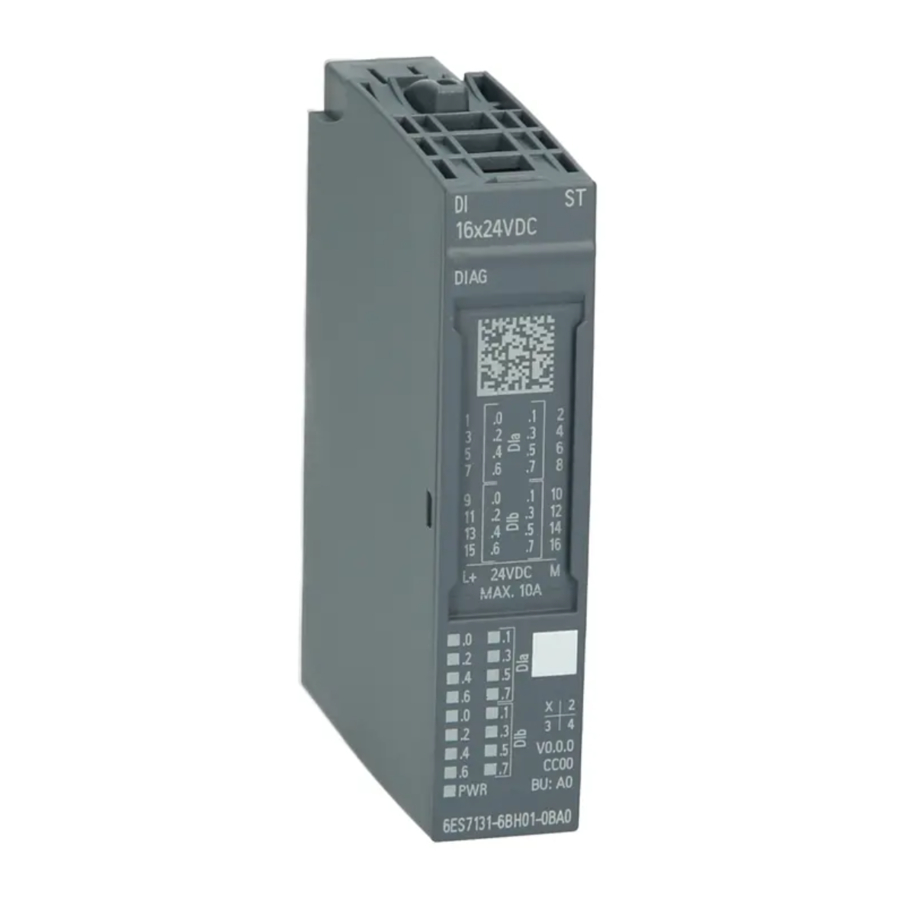
Description
The I/O module consists of the following components:

- Module type color coding
- Function version
- Color code for selection of the color-coded labels
- Serial number
- Article number
- LED for supply voltage
- LEDs for channel status/channel fault
- Connection diagram
- 2D matrix code
- LED for maintenance
- LED for diagnostics
- Module type and designation
Accessories
Definition
Accessories for the I/O module must be ordered separately.
Description
The following accessories must be ordered separately:
- Labeling strips
- Color-coded labels
- Reference identification label
- Shield connector
Terminal blocks
Definition
The terminal blocks provide the process terminals (push-in terminals) and the terminal blocks with D-SUB connectors for components to be connected, such as devices.
Note
Terminal blocks are not included in the scope of delivery of the I/O module and must be ordered separately.
Refer to the System Manual for the terminal blocks available for the I/O module and more information on configuration.
Terminal
Pin assignment
Definition
The terminal assignment provides information about the arrangement and marking of the terminals when wiring a connector.
Description
The general pin assignment is structured as follows:
| Terminal | Assignment | Terminal | Assignment | Explanations |
| 1 | DI.0- | 2 | DI.1- |  DIn: Input signal, channel n (0...15) 1P1: Supply voltage L+ of the voltage bus 1P 2P1: Supply voltage L+ of the voltage bus 2P 1P2: Ground reference of the voltage bus 1P 2P2: Ground reference of the voltage bus 2P |
| 3 | DI.2- | 4 | DI.3- | |
| 5 | DI.4- | 6 | DI.5- | |
| 7 | DI.6- | 8 | DI.7- | |
| 9 | DI.8- | 10 | DI.9- | |
| 11 | DI.10- | 12 | DI.11- | |
| 13 | DI.12- | 14 | DI.13- | |
| 15 | DI.14- | 16 | DI.15- | |
| 17 | M | 18 | M | |
| 19 | M | 20 | M | |
| 21 | M | 22 | M | |
| 23 | M | 24 | M | |
| 25 | M | 26 | M | |
| 27 | M | 28 | M | |
| 29 | M | 30 | M | |
| 31 | M | 32 | M | |
| 1P1 | L+ | 1P2 | M | |
| 2P1 | L+ | 2P2 | M |
Example of a wiring diagram for switches

Example
The figure above shows the connection of mechanical switches
Sample connection scheme for 2-wire connection

Example
The following picture shows the connection of a 2-wire sensor according to IEC61131, types 1 and 3.
Sample connection scheme for 3-wire connection

Example
The following picture shows the connection of a 3-wire sensor according to IEC61131, types 1 and 3.
Schematic circuit diagram
Definition
A block diagram contains the schematic representation of individual function blocks.
Description
The block diagram for the I/O module is structured as follows:

Parameters
Module/channel parameters
Definition
Module/channel parameters are specific parameters whose configuration can affect the entire module or the channels.
Description
The following module/channel parameters are available:
Table 6-1 Parameters and their defaults
| Parameter | Value range | Default | Parameter reassignment in RUN | Efficiency range |
| Diagnostics for Missing supply voltage L+ (see "Diagnostics for Missing supply voltage L+") |
| Enabled | Yes | Module |
| Diagnostics for Wire break (see "Diagnostics for Wire break")1 |
| Enabled | Yes | Channel |
| Wire break check (see "Wire break check") |
| Enabled | Yes | Channel |
| Channel activated (see "Channel activated") |
| Enabled | Yes | Channel |
| Input delay (see "Input delay")1 for channels 0...7 |
| 3.2 ms | Yes | Channel |
| Input delay (see "Input delay") for channels 8...15 | 3.2 ms | 3.2 ms | No | Channel |
| Hardware interrupts positive edge (see "Hardware interrupts positive edge")2 |
| Disabled | Yes | Channel |
| Hardware interrupts negative edge (see "Hardware interrupts negative edge")2 |
| Disabled | Yes | Channel |
| Potential group (see "Potential group") |
| Use potential group of the left module | No | Module |
1 The input delay is switched off on all channels when high precision time stamping is activated. When high precision time stamping is activated, pulse stretching and the rising/falling edge hardware interrupt are deactivated on all channels (not adjustable).
Parameter reassignment
Definition
Each configuration change resets the corresponding reaction. Changing the configuration of a function does not affect other functions.
Explanation of the module/channel parameters
Diagnostics for Missing supply voltage L+
Definition
Enabling of the diagnostics for detecting missing or insufficient supply voltage L+.
Diagnostics for Wire break
Definition
When wire-break diagnostics is activated, you can enable wire-break diagnostics for insufficient current flow on the input.
Note
The wire break diagnostics can only be enabled when the "Check for wire break" parameter is enabled. If you use a simple encoder contact, you need to connect a parallel resistor to enable wire break diagnostics in the open state (sensor resistance for wire break diagnostics: 15 kΩ to 47 kΩ).

Example
Wire break check
Definition
Enables the wire break check. The wire break check must be enabled in order for the I/O module to detect a wire break.
Channel activated
Definition
Specifies whether a channel is activated or deactivated.
Input delay
Definition
This parameter can be used to avoid signal faults. Changes to the signal are only detected if they are constantly pending longer than the set input delay time.
For input channels with longer input delays, the read-in time is moved accordingly. This means individual channels can be assigned input delays, if necessary, without having a negative impact on the possible cycle time.
Hardware interrupts positive edge
Definition
Specifies if a hardware interrupt should be generated for a rising edge.
Hardware interrupts negative edge
Definition
Specifies if a hardware interrupt should be generated for a negative edge.
Potential group
Definition
A potential group consists of a group of directly adjacent I/O modules within an ET 200SP HA station that are supplied via a common supply voltage.
Description
A potential group is built up from left to right by using terminal blocks.
A new potential group starts on the left side with a light gray terminal block, via which the supply voltage for the potential group is fed in.
The potential group is continued to the right with dark gray terminal blocks and ends when a new potential group is built up next to it.
The potential group also ends if there is a black terminal block next to it. Black terminal blocks are fed individually and cannot be included in potential groups.
You can find additional information on the configuration of the potential group in the system manual SIMATIC; Distributed I/O System; ET 200SP HA.
Displays and interrupts
Status and error displays
Definition
The LED displays are status and error indicators.
Diagnostics messages and maintenance events, as well as their possible causes or solutions, are described in the diagnostics messages and maintenance events.
Diagnostics messages (see "Diagnostics messages")
Description
The following figure explains the LED displays of the I/O module.

- AUTOHOTSPOT (green/red)
- AUTOHOTSPOT (yellow)
- AUTOHOTSPOT (green)
- Channel fault LED (see "Channel status/fault LED") (red)
- Channel status LED (see "Channel status/fault LED") (green)
LEDs
DIAG LED
Definition
The DIAG LED provides you with diagnostics information.
Description
The diagnostics display of the DIAG LED is as follows:
| DIAG LED | Meaning |
 Off | The supply voltage of the ET 200SP HA is disrupted or disabled. |
 flashes | Module is not configured. |
 On | Module parameters are assigned. No diagnostic message is pending. |
 flashes | Module parameters are assigned. At least one diagnostic message is pending. |
MT LED
Definition
The MT LED provides maintenance information.
Description
The MT LED indicates the following maintenance status:
| MT LED | Meaning |
 Off | No maintenance is required. |
 On | Maintenance is required. At least one maintenance event has occurred. |
Channel status / fault LEDs
Definition
The channel status and channel fault LEDs provide you information about the status and faults of the channels.
Description
Regardless of the parameter assignment, the green LED channel status shows the signal level at the input terminal. It lights up starting at approximately 10 V of terminal current.
The red channel fault LED lights up when a channel diagnostics is active for an enabled channel.
The channel status and channel fault LEDs indicate the following:
| LED channel status | LED channel error | Meaning |
| Off |  Off | Process signal = 0 and
|
| On | Off | Process signal = 1 and
|
| Off |  On | Process signal = 0 and
|
| On | On | Process signal = 1 and
|
PWR LED
Definition
The PWR LED provides you status information about supply voltage L+.
Description
The PWR LED indicates the following status:
| PWR LED | Meaning |
| Off | Supply voltage L+ missing. |
| On | Supply voltage L+ present. |
Interrupts
Definition
A diagnostics interrupt is an alarm that reports activated events of a device status to the system operator with the appropriate operating authorization (maintenance and service).
Description
The I/O module generates a diagnostics interrupt at the following events:
- Supply voltage missing
- Wire break
- Parameter assignment error
- Hardware interrupt lost
- Channel/component temporarily unavailable
- Retentive memory in carrier module defective
- Retentive memory in the terminal block defective
Technical specifications
Technical specifications of the DI 16X24VDC NPN
| Article number | 6DL1131-6BH60-0PH1 |
| General information | |
| Product type designation | DI 16x24VDC NPN HA |
| Firmware version | V1.0 |
| Yes |
| Usable terminal block | see the system manual |
| Color code for module-specific color identifica‐ tion plate | CC02 |
| Product function | |
| Yes; I&M0 to I&M3 |
| Engineering with | |
| V9.1 SP3 / V10 |
| Operating mode | |
| Yes |
| No |
| No |
| No |
| Redundancy | |
| No |
| CiR - Configuration in RUN | |
| Reparameterization possible in RUN | Yes |
| Supply voltage | |
| Rated value (DC) | 24 V |
| permissible range, lower limit (DC) | 19.2 V |
| permissible range, upper limit (DC) | 28.8 V |
| Reverse polarity protection | Yes |
| Encoder supply | |
| Number of outputs | 16 |
| Output voltage (DC) | 0 V |
| Short-circuit protection | No |
| 24 V encoder supply | |
| No |
| Power loss | |
| Power loss, typ. | 1.2 W |
| Address area | |
| Address space per module | |
| 2 byte; + 2 bytes for QI information |
| Hardware configuration | |
| Automatic encoding | |
| Yes |
| Digital inputs | |
| Number of digital inputs | 16 |
| Digital inputs, parameterizable | Yes |
| Source/sink input | Yes; Sourcing |
| Input characteristic curve in accordance with IEC 61131, type 1 | Yes |
| Input characteristic curve in accordance with IEC 61131, type 2 | No |
| Input characteristic curve in accordance with IEC 61131, type 3 | Yes |
| Pulse extension | No |
| Time stamping | Yes; Resolution 10 ms |
| Edge evaluation | Yes; rising edge, falling edge, edge change |
| Number of simultaneously controllable inputs | |
| 16 |
| Input voltage | |
| 24 V |
| 30 V to -5 V (reference potential is L+) |
| -11 V to -30 V (reference potential is L+) |
| Input current | |
| 3 mA |
| Input delay (for rated value of input voltage) for standard inputs | |
| Yes; None / 0.05 / 0.1 / 0.4 / 0.8 / 1.6 / 3.2 / 12.8 / 20 ms (in each case + delay of 30 µs to 500 µs, de‐ pending on line length) |
| Cable length | |
| 1 000 m |
| 600 m |
| Encoder | |
| Connectable encoders | |
| Yes |
| 1.5 mA |
| Interrupts/diagnostics/status information | |
| Alarms | |
| Yes; channel by channel |
| Yes; channel by channel |
| Diagnoses | |
| Yes |
| Yes; Module-wise |
| Yes |
| No |
| Yes; channel by channel |
| No |
| Diagnostics indication LED | |
| Yes; Yellow LED |
| Yes; green PWR LED |
| Yes; green LED |
| Yes; red LED |
| Yes; green/red DIAG LED |
| Potential separation | |
| Potential separation channels | |
| No |
| Yes |
| No |
| Isolation | |
| Isolation tested with | 1 500 V DC/1 min, type test |
| Ambient conditions | |
| Ambient temperature during operation | |
| -40°C |
| 70°C |
| -40°C |
| 60°C |
| Dimensions | |
| Width | 22.5 mm |
| Height | 115 mm |
| Depth | 138 mm |
| Weights | |
| Weight, approx. | 150 g |
Cycle time
The cycle time describes the time slice in which signals from the inputs are acquired and processed. The cycle time of the I/O module is 1 ms (250 μs for time stamping).
Minimum pulse length
In order for a pulse or an edge transition to be reliably detected by the I/O module, the signal status must be active for at least the duration of the minimum pulse length.
In non-redundant mode, the minimum pulse length is greater than the input delay and greater than the cycle time.
Drivers/parameters/diagnostics messages and address space
Parameter assignment
Parameter assignment in the user program
You can reconfigure individual channels of the module in RUN without this having an effect on the other channels.
Changing parameters in RUN
The parameters are transferred to the module with the "WRREC" instruction via data record 128.
Output parameter STATUS
If errors occur when transferring parameters with the "WRREC" instruction, the module continues operation with the previous parameter assignment. The STATUS output parameter contains the corresponding error code.
The STATUS output parameter is 4 bytes long and is configured as followed:
- Byte1: Function_Num, general error code
- Byte2: Error_Decode, location of the error code
- Byte3: Error_Code_1, error code
- Byte4: Error_Code_2, manufacturer-specific extension of the error code
Module-specific errors are displayed via Error_Decode = 0x80 and Error_Code_1 / Error_Code_2.
| Error_ Code_1 | Error_Code_2 | Cause | Remedy |
| 0xB0 | 0x00 | Number of the data record unknown | Enter valid number for data record. |
| 0xB1 | 0x01 | Length of the data record is incorrect | Enter valid value for data record length. |
| 0xB2 | variable | Module cannot be reached |
|
| 0xE0 | 0x01 | Wrong version in the header | Correct the version number of the parameter block. |
| 0xE0 | 0x02 | Header error (number or length of parameter block) | Correct the length and number of the parameter blocks. |
| 0xE1 | 0x01 | Reserved bit set | Check and correct the parameters |
| 0xE1 | 0x02 | Invalid diagnostics enable bit set for operating mode | |
| 0xE1 | 0x03 | Invalid hardware interrupt enable bit set for operating mode | |
| 0xE1 | 0x07 | Invalid coding for input delay |
Parameter assignment and structure of the module/channel parameters
Structure of data record 128 (Fig. A-1)
Data record 128 has a length of 44 bytes.
It contains module parameters as well as channel or technology parameters of the 16 channels; 2 bytes each.

Header information and module parameters (Fig. A-2)
The following figure shows the configuration of the header information and module parameters.

Channel parameters (Fig. A-3)
Every channel parameter block contains the channel parameters for the digital input (2 bytes).
The following figure shows the configuration of the channel parameters for channels 0 to 15.
x = 12 + (channel number * 2); with channel number 0...15
All unused bits and the bits or bytes marked as "reserved" must be set to zero.
You activate a channel parameter by setting the corresponding bit to "1" or the corresponding value.

Diagnostics messages
Diagnostics alarms
A diagnostics message is generated for each diagnostics event and the DIAG LED on the DI 16×24VDC NPN flashes red or the MT LED lights up yellow.
In addition, channel-specific channel diagnostics are displayed through the corresponding channel error/status LEDs.
The diagnostics messages can be read in the diagnostics buffer of the CPU, for example.
Diagnostic messages are assigned either channel-specific to an input or assigned as module messages to all inputs. All channels are switched off for diagnostics messages that affect the entire module. Only the corresponding digital input is affected by diagnostics messages, which refer to individual channels.
Table A-1 Diagnostic messages, their meanings and remedy options
| Diagnostics message | Error code | Assignment | Meaning | Remedy |
| Wire break | 6H | Channel | Impedance of encoder circuitry is too high | Use another type of encoder or wiring, for example, use conductors with a larger cross-section |
| Wire break between the module and sensor | Connect the cable | |||
| Channel not connected (open) |
| |||
| Parameter assignment error | 10H | Module |
|
|
| Supply voltage missing | 11H | Module | Missing or insufficient supply voltage L+ |
|
| Hardware interrupt lost | 16H | Module | Error is reported because the events occur faster than they can be processed in the system. | |
| Channel/component temporarily unavailable | 1FH | Module | Firmware update is in progress or has been canceled during the update. The module does not read any process values in this state. |
|
| Inconsistent parameter assignment | 123H | Module | Errors in the redundancy parameters sent to the module | Check the parameter assignment |
| Retentive memory in carrier module defective | 154H | Module | Fault detected in the memory block on the carrier module during startup. | Replace carrier module |
| Retentive memory in the terminal block defective | 155H | Module | Fault detected in the memory block on the terminal block during startup. | Replace terminal block |
1) 47 kΩ resistors can be used provided that the following supplementary conditions are complied with: Only singular structure of the I/O modules (no IO redundancy); the process cables are shielded; no certification required according to the following standards: NE21 or Power Station 6100-6-5
2) Only the terminal blocks (TB 45R...) are suitable for use with I/O modules in IO redundancy.
Maintenance events
Maintenance events
A maintenance event is generated for each maintenance required identified. The MT LED lights up on the module.
Maintenance messages do not have a direct influence on the functions of the module or digital inputs.
| Maintenance message | Error code | Assignment | Meaning / Cause | Remedy |
| Retentive memory in carrier module defective | 154H | Module | Fault detected in the memory block on the carrier module during operation. | Replace carrier module |
| Retentive memory in the terminal block defective | 155H | Module | Fault detected in the memory block on the terminal block during operation. | Replace terminal block |
Hardware interrupts
Hardware interrupts
The DI 16×24VDC NPN generates a hardware interrupt for the following events:
- At a rising edge (signal change from 0 to 1)
- At a falling edge (signal change from 1 to 0)
Interrupt OBs are called automatically if an interrupt occurs.
You can find detailed information on the event in the hardware interrupt organization block with the "RALRM" instruction (read additional interrupt information).
The module channel that triggered the hardware interrupt is recorded in the start information of the OB40 in the OB40_POINT_ADDR tag. The figure A-4 below shows the assignment to the bits of local data double word 8.

Address space
Abbreviations
- "IB" stands for input byte, that is, the module start address in the input area
- "DI" stands for digital input
- "QDIn" stands for the value status (QI) of digital input n
Address space
The following table shows the mapping of the address space of the DI 16x24VDC NPN.
Table A-2 Address space of the DI 16x24VDC NPN
| IB x + | 7 | 6 | 5 | 4 | 3 | 2 | 1 | 0 |
| 0 | DI7 | DI6 | DI5 | DI4 | DI3 | DI2 | DI1 | DI0 |
| 1 | DI15 | DI14 | DI13 | DI12 | DI11 | DI10 | DI9 | DI8 |
| 2 | QDI7 | QDI6 | QDI5 | QDI4 | QDI3 | QDI2 | QDI1 | QDI0 |
| 3 | QDI15 | QDI14 | QDI13 | QDI12 | QDI11 | QDI10 | QDI9 | QDI8 |
Evaluate value status
There is a bit value status for each digital input in the input address space.
Irrespective of the diagnostics enables, each value status (each QI bit) provides information on the validity of the corresponding process value.
- Value status = 1: Process value okay, "good"
- Value status = 0: Process value not okay, "bad"
Basically, the value status is set to "good" if the digital value can be detected without error. The value status is set to "bad" in the following cases:
- The digital value cannot be output due to an error.
- The digital channel is deactivated.
Note
The value status is not set to "bad" when there is a wire break on the channel and the wire break test is disabled.
Documents / Resources
References
Download manual
Here you can download full pdf version of manual, it may contain additional safety instructions, warranty information, FCC rules, etc.
Download Siemens SIMATIC ET 200SP HA, SIMATIC DI 16x24VDC NPN Manual
Advertisement


Need help?
Do you have a question about the SIMATIC ET 200SP HA and is the answer not in the manual?
Questions and answers