
Related Manuals for Qlogic QLE2740L-DEL


Summary of Contents for Qlogic QLE2740L-DEL
- Page 1 User’s Guide Fibre Channel Adapter QLE2740-DEL, QLE2740L-DEL, QLE2742-DEL, and QLE2742L-DEL Third party information brought to BK3254601-00 C you courtesy of Dell EMC.
-
Page 2: Document Revision History
This document is provided for informational purposes only and may contain errors. QLogic reserves the right, without notice, to make changes to this document or in product design or specifications. QLogic disclaims any warranty of any kind, expressed or implied, and does not guarantee that any results or performance described in the document will be achieved by you. - Page 3 User’s Guide—Fibre Channel Adapter QLE274x-DEL and QLE274xL-DEL In the introductory paragraph, changed the envi- “Installing the QLogic Adapter CIM Provider” on ronment reference from “ESXi 5.5 and ESXi 6.0” to page 26 “ESXi 6.5 and ESXi 6.0 U2”. Changed the section title from “Installing the CIM “Installing the CIM Provider on an ESXi 6.5 or 6.0...
-
Page 4: Table Of Contents
Table of Contents Introduction Intended Audience ..........User’s Guide Content . - Page 5 Server Plug-in........Installing the QLogic Adapter CIM Provider ....
- Page 6 User’s Guide—Fibre Channel Adapter QLE274x-DEL and QLE274xL-DEL Configuring Target Persistent Binding ......Configuring Persistent Binding with QConvergeConsole GUI.
- Page 7 User’s Guide—Fibre Channel Adapter QLE274x-DEL and QLE274xL-DEL Setting the FA-PWWN from the Brocade Switch....Setting the FA-PWWN from the Switch ....Setting the Static FA-PWWN from the Switch.
- Page 8 Enabling QLogic FEC ........
- Page 9 Downloading and Installing Management Agents ....Installing the Agents from the QLogic Web Site ....
-
Page 10: Introduction
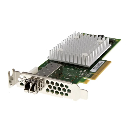
® QLogic QLE2740-DEL single-port, low profile adapter with a full-height bracket QLogic QLE2740L-DEL single-port, low profile adapter with a low profile bracket QLogic QLE2742-DEL dual-port, low profile adapter with a full-height bracket QLogic QLE2742L-DEL dual-port, low profile adapter with a low profile... -
Page 11: Related Materials
Appendix D Regulatory Information provides warranty, regulatory, and compliance information. Related Materials For additional information, refer to the following QLogic documents: QConvergeConsole Help, available through QConvergeConsole GUI, provides help topics on configuring and managing host servers and adapters using QConvergeConsole GUI. -
Page 12: Documentation Conventions
Press the UP ARROW key Text in italics indicates terms, emphasis, variables, or document titles. For example: For a complete listing of license agreements, refer to the QLogic Software End User License Agreement. What are shortcut keys? ... - Page 13 Introduction Documentation Conventions Topic titles between quotation marks identify related topics either within this manual or in the online help, which is also referred to as QConvergeConsole Help throughout this document. QConvergeConsole CLI non-interactive command syntax conventions include the following: ...
-
Page 14: Functionality And Features
QLE2740-DEL: A low profile, Gen6 32Gb, single-port Fibre Channel PCIe adapter with a full-height bracket installed. QLE2740L-DEL: A low profile, Gen6 32Gb, single-port Fibre Channel PCIe adapter with a low profile bracket installed. QLE2742-DEL: A low profile, Gen6 32Gb, dual-port Fibre Channel PCIe adapter with a full-height bracket installed. -
Page 15: Supported Operating Systems
Introduction Functionality and Features Supported Operating Systems NOTE Because the Dell Update Packages Version xx.xx.xxx User’s Guide is not updated in the same cycle as this Fibre Channel adapter user’s guide, consider the operating systems listed in this section as the more current. The adapter supports the following operating systems. -
Page 16: Hardware Installation
Hardware Installation This chapter provides the hardware and software requirements, safety precautions, a pre-installation checklist, PCIe slot considerations, and procedures for installing the adapter and connecting it to the network. Hardware and Software Requirements Before you install the adapter, verify that the system meets the following hardware and software requirements. -
Page 17: Pre-Installation Checklist
Model Number Required to Achieve FC Ports Slot Configurations Line Rate PCIe 2.0 x8 and higher QLE2740-DEL, 32Gbps (1 32Gbps) QLE2740L-DEL PCIe 3.0 x8 and higher QLE2742-DEL, 64Gbps (2 32Gbps) PCIe 3.0 x8 and higher QLE2742L-DEL BK3254601-00 C... -
Page 18: Installing The Adapter
1–Hardware Installation Installing the Adapter Installing the Adapter To install the QLE274x-DEL Adapters: Power off the computer and all attached devices such as monitors, printers, and external components. Disconnect the power cable. Remove the computer cover and find an empty PCIe bus slot. For more information about selecting a bus slot, see “PCIe Bus Slot Considerations”... -
Page 19: Driver Installation And Configuration
Driver Installation and Configuration NOTE If you need to update the Flash memory of multiple adapters simultaneously: For QConvergeConsole GUI, refer to the “Update the Flash Using the Flash Update Wizard” topic in the QConvergeConsole Help. For QConvergeConsole CLI, issue the -flashsupport command to update the Flash memory for all cards supported by the specified file. -
Page 20: Running The Dell Update Package In The Gui
2–Driver Installation and Configuration Windows Driver Installation and Configuration Running the Dell Update Package in the GUI Before you begin, refer to the Dell Update Packages Version xx.xx.xxx User’s Guide, “Prerequisites and Features for Systems Running Windows” section. To run the Dell update package in the GUI: Double-click the icon representing the Dell update package file. - Page 21 2-2), click Next. Figure 2-2. QLogic InstallShield Wizard: Welcome Window In the wizard’s License Agreement window (Figure 2-3 on page Read the QLogic End User Software License Agreement. To continue, select I accept the terms in the license agreement. BK3254601-00 C...
- Page 22 2–Driver Installation and Configuration Windows Driver Installation and Configuration Click Next. Figure 2-3. QLogic InstallShield Wizard: License Agreement Window Complete the wizard’s Setup Type window (Figure 2-4) as follows: Select one of the following setup types: Click Complete to install all program features.
- Page 23 2–Driver Installation and Configuration Windows Driver Installation and Configuration If you selected Complete, proceed directly to Step 6 Figure 2-4. InstallShield Wizard: Setup Type Window If you selected Custom in Step 5, complete the Custom Setup window (Figure 2-5 on page 9) as follows: Select the features to install.
- Page 24 2–Driver Installation and Configuration Windows Driver Installation and Configuration Click Next to continue. Figure 2-5. InstallShield Wizard: Custom Setup Window In the InstallShield Wizard’s Ready To Install window (Figure 2-6), click Install. Figure 2-6. InstallShield Wizard: Ready to Install the Program Window BK3254601-00 C...
- Page 25 2–Driver Installation and Configuration Windows Driver Installation and Configuration The InstallShield Wizard installs the QLogic Adapter drivers and Management Software Installer. When the installation is complete, the InstallShield Wizard Completed window appears (Figure 2-7). Click Finish to dismiss the installer.
-
Page 26: Running The Dell Update Package From The Command Line
2–Driver Installation and Configuration Windows Driver Installation and Configuration Figure 2-8. Dell Update Package Window Running the Dell Update Package from the Command Line For a list of the CLI options for systems running Windows, a description of each option, and the command syntax, refer to the Dell Update Packages Version xx.xx.xxx User’s Guide, “Windows CLI Options”... -
Page 27: Linux Driver Installation And Configuration
2–Driver Installation and Configuration Linux Driver Installation and Configuration To extract the driver components to the C:\mydir\ directory: <DUP_file_name>.exe /s /drivers=C:\mydir To install only the driver components: <DUP_file_name>.exe /s /driveronly To change from the default log location to C:\my path with spaces\log.txt: <DUP_file_name>.exe /l="C:\my path with spaces\log.txt"... -
Page 28: Building The Driver For Rhel 6.X And 7.X
2–Driver Installation and Configuration Linux Driver Installation and Configuration Building the Driver for SLES 11 Building the Driver for SLES 12 Building the Driver for RHEL 6.x and 7.x From the directory that contains the source driver file, qla2xxx-src-vx.xx.xx.xx.06.x-k.tar.gz, issue the appropriate commands for your Linux version. -
Page 29: Building The Driver For Sles 11
2–Driver Installation and Configuration Linux Driver Installation and Configuration To unload the driver using modprobe, issue the following command: # modprobe -r qla2xxx (Optional) To automatically load the driver each time the system boots, rebuild the RAM disk to include the driver as follows: Create a backup copy of the RAMDISK image by issuing the following commands: # cd /boot... -
Page 30: Building The Driver For Sles 12
2–Driver Installation and Configuration Linux Driver Installation and Configuration (Optional) Manually load the driver for Linux. Edit the /etc/modprobe.d/unsupported_modules file to make the following change: with allow_unsupported_modules 1 (replace 0 To load the driver using modprobe, issue the following command: # modprobe -v qla2xxx ... -
Page 31: Vmware Driver Installation And Configuration
2–Driver Installation and Configuration VMware Driver Installation and Configuration Adds the appropriate directive in the modprobe.conf file (if applicable). NOTE You can optionally complete either or both Step 3 Step 4 of this procedure. (Optional) Manually load the driver for Linux. ... -
Page 32: Installation Overview
2–Driver Installation and Configuration VMware Driver Installation and Configuration Installation Overview To install and configure the adapter drivers on a VMware system, refer to the driver release notes and readme files included in the package. Installing the ESXi 6.5 and 6.0 U2 Fibre Channel Driver The operating system manages and controls the driver installation process. -
Page 33: Verifying The Version Of The Installed Driver
“Uninstalling the QConvergeConsole VMware vCenter Server Plug-in” on page 26 “Installing the QLogic Adapter CIM Provider” on page 26 “Uninstalling the QLogic Adapter CIM Provider” on page 29 For information on installing the Plug-in, refer to “Installing QConvergeConsole VMware vCenter Server Plug-in”... -
Page 34: Installation Package Contents
VMware Driver Installation and Configuration Installation Package Contents The latest version of the QLogic Adapter CIM Provider and QConvergeConsole VMware vCenter Server Plug-in package contains the files needed to install both the Plug-in and the CIM Provider. Required files include the following (where x_x_x is the version number): ... - Page 35 VMware Driver Installation and Configuration The InstallAnywhere wizard opens, as shown in Figure 2-9. Figure 2-9. InstallAnywhere Initial Window In the QLogic Adapter VI Plug-in wizard’s Introduction window (see Figure 2-10), click Next. Figure 2-10. QLogic Adapter VI Plug-in Wizard: Introduction BK3254601-00 C...
- Page 36 VMware Driver Installation and Configuration Wait while the wizard configures the plug-in (see Figure 2-11). Figure 2-11. QLogic Adapter VI Plug-in Wizard: Configuring the Plug-in Select the installation directory, and then click Install (see Figure 2-12). Figure 2-12. QLogic Adapter VI Plug-in Wizard: Choose Install Folder...
- Page 37 2–Driver Installation and Configuration VMware Driver Installation and Configuration Wait while the wizard performs the installation (see Figure 2-13). Figure 2-13. QLogic Adapter VI Plug-in Wizard: Installing the Plug-In BK3254601-00 C...
- Page 38 2–Driver Installation and Configuration VMware Driver Installation and Configuration Type the requested information in the boxes, then click Next (see Figure 2-14). Figure 2-14. QLogic Adapter VI Plug-in Wizard: User Input BK3254601-00 C...
- Page 39 2–Driver Installation and Configuration VMware Driver Installation and Configuration Wait while the wizard finishes configuring the plug-in (see Figure 2-15). Figure 2-15. QLogic Adapter VI Plug-in Wizard: Configuration in Progress BK3254601-00 C...
-
Page 40: Plug-In Unregistration From A Manual Install
When the Registration Result window (Figure 2-16) appears, click Finish to exit. Figure 2-16. QLogic Adapter VI Plug-in Wizard: Registration Result After the installation completes, restart the Tomcat service as follows: If the plug-in is installed on the VMware vCenter Server, restart the ... -
Page 41: Uninstalling The Qconvergeconsole Vmware Vcenter Server Plug-In
VMware vCenter Server Plug-in installer. Installing the QLogic Adapter CIM Provider This section describes how to install, start, and remove the QLogic Adapter CIM Provider for VMware ESXi. Because there are multiple zip packages, ensure that you pick the zip package that matches your environment: ESXi 6.5 and ESXi 6.0... - Page 42 “Remote Installation of the CIM Provider on an ESXi Host” on page Installing the CIM Provider on an ESXi 6.5 or 6.0 U2 Host Copy the following file to the root directory (/) of the ESXi 6.5 system: QLGC-ESX-5.5.0-qlogic-adapter-provider- xxxxxxx offline_bundle- .zip...
- Page 43 Command-Line Interface Installation and Reference Guide at: http://www.vmware.com/pdf/vsphere4/r40/vsp_40_vcli.pdf Subsequent Update Installation To update the QLogic Adapter CIM Provider after a prior VIB installation, follow the instructions in “Uninstalling the QLogic Adapter CIM Provider” on page 29 remove the existing VIB. After completing the VIB removal, use the same steps in “Initial Installation Methods”...
-
Page 44: Uninstalling The Qlogic Adapter Cim Provider
To restart the SFCB CIMOM and the QLogic Adapter CIM Provider: # /etc/init.d/sfcbd-watchdog restart After starting the SFCB CIMOM, use a CIM client utility to query the QLogic Adapter CIM Provider for information. Uninstalling the QLogic Adapter CIM Provider You can uninstall the QLogic Adapter CIM Provider for your version of VMware. -
Page 45: Installing Qconvergeconsole Vmware Vsphere Web Client Plug-In
2–Driver Installation and Configuration VMware Driver Installation and Configuration NOTE For more details on vihostupdate, see the vSphere Command-Line Interface Installation and Reference Guide, located here: http://www.vmware.com/pdf/vsphere4/r40/vsp_40_vcli.pdf Installing QConvergeConsole VMware vSphere Web Client Plug-in Gather the information necessary for the installation, including: ... -
Page 46: Uninstalling The Qconvergeconsole Vmware Vcenter Server Plug-In
Linux is initiated by the following command line command: /opt/qlogic/QLogic\ Adapter\ Web\ Client\ Plugin/Uninstall_QLogic\ Adapter\ Web\ Client\ Plugin/Uninstall\ QLogic\ Adapter\ Web\ Client\ Plugin Follow the prompts (user interface or console commands) to uninstall the plug-in by the root user. -
Page 47: Fibre Channel Configuration
“Configuring End-to-End CS_CTL QoS” on page 84 “Configuring FDMI” on page 90 “Enabling QLogic Forward Error Correction” on page 94 “Running Extended Link Service Commands” on page 96 NOTE For information on configuring the Fibre Channel Adapter using VMware vCenter Server, refer to the User’s Guide—QConvergeConsole Plug-ins for... -
Page 48: Updating The Dell Firmware
3–Fibre Channel Configuration Updating the Dell Firmware Updating the Dell Firmware The firmware Dell update package is a Flash update utility only; it is not used for adapter configuration. To run the firmware Dell Update Package, double-click the executable file. Alternatively, run the firmware Dell Update Package from the command line, which supports several command line options. - Page 49 3–Fibre Channel Configuration Updating the Dell Firmware Follow the installer instructions. If a warning message appears (Figure 3-2), click Yes to continue the installation. Figure 3-2. Continue Dell Update Package Installation The installer indicates that it is loading the new firmware (Figure 3-3).
-
Page 50: Running The Firmware Update From The Command Line
3–Fibre Channel Configuration Updating the Dell Firmware When complete, the installer indicates the result of the installation (Figure 3-4). Click Yes to elect to reboot. Figure 3-4. Result of Installation To complete the installation, click Finish (Figure 3-5). Figure 3-5. Finish Installation Running the Firmware Update from the Command Line Running the firmware Dell update package from the command line, with no options specified, results in the same behavior as double-clicking the icon... -
Page 51: Using Fast!Util For Custom Configuration
Using Fast!UTIL for Custom Configuration This section provides detailed configuration information for advanced users who want to customize the configuration of the adapters and connected devices using Fast!UTIL (the QLogic Fibre Channel Adapter BIOS utility) in a pre-OS environment. To configure adapters using Fast!UTIL: During the Host Bus Adapter BIOS initialization, press ALT+Q or CTRL+Q. -
Page 52: Configuration Settings
3–Fibre Channel Configuration Using Fast!UTIL for Custom Configuration To load the new parameters, reboot the system. CAUTION If the configuration settings are incorrect, your 2700 Series Adapter may not function properly. The Fast!UTIL Options menu provides the following options: “Configuration Settings”... - Page 53 3–Fibre Channel Configuration Using Fast!UTIL for Custom Configuration Table 3-1. Adapter Settings (Continued) Setting Values Default Description 0–60 After resetting the loop, the firmware refrains from initiating Loop Reset seconds seconds any loop activity for the number of seconds specified in this Delay setting.
-
Page 54: Selectable Boot Settings
3–Fibre Channel Configuration Using Fast!UTIL for Custom Configuration Selectable Boot Settings The Configuration Settings menu provides access to the Selectable Boot Settings options. If you enable the Host Bus Adapter BIOS in the adapter settings, you can select the boot device, as shown in Table 3-2. -
Page 55: Restore Default Settings
NOTE System BIOS compatibility: To boot from a QLogic host 2700 Series Adapter in a computer system with a multiboot system BIOS, the 2700 Series Adapter must be included in the list of bootable devices in the system’s Boot menu. -
Page 56: Scan Fibre Devices
3–Fibre Channel Configuration Using Fast!UTIL for Custom Configuration Table 3-3. Advanced Adapter Settings (Continued) Setting Values Default Description Yes, No When this setting is Yes, the drivers issue a Target Reset Enable command to all devices on the loop when a SCSI Bus Reset Target command is issued. -
Page 57: Fibre Disk Utility
3–Fibre Channel Configuration Using Fast!UTIL for Custom Configuration Fibre Disk Utility The Fibre Disk Utility option scans the Fibre Channel loop and lists all the connected devices by loop ID. You can select a Fibre Channel hard disk and do one of the following tasks: ... -
Page 58: Setting Fibre Channel Adapter Parameters
3–Fibre Channel Configuration Setting Fibre Channel Adapter Parameters Setting Fibre Channel Adapter Parameters Use QConvergeConsole to set Fibre Channel adapter parameters: Setting Fibre Channel Adapter Parameters with QConvergeConsole GUI Setting Fibre Channel Adapter Parameters with Interactive QConvergeConsole CLI ... -
Page 59: Configuring Target Persistent Binding
3–Fibre Channel Configuration Configuring Target Persistent Binding Configuring Target Persistent Binding NOTE Target persistent binding is supported only on Windows. Use QConvergeConsole to configure target persistent binding: Configuring Persistent Binding with QConvergeConsole GUI Configuring Persistent Binding with Interactive QConvergeConsole CLI ... -
Page 60: Configuring Persistent Binding With Interactive
3–Fibre Channel Configuration Configuring Boot Devices Configuring Persistent Binding with Interactive QConvergeConsole CLI To bind a target using interactive QConvergeConsole CLI: On the Fibre Channel Adapter Configuration menu, select Target Persistent Bindings. On the port menu, select a port and then select Bind Target(s) to bind a target to a port. -
Page 61: Configuring Boot Devices With Qconvergeconsole Gui
3–Fibre Channel Configuration Configuring Boot Devices Configuring Boot Devices with Noninteractive QConvergeConsole CLI Configuring Boot Devices with the BIOS Configuring Boot Devices with QConvergeConsole GUI For information about configuring boot devices with QConvergeConsole GUI, refer to the topics about HBA parameters, viewing or modifying port parameters, and boot device selection in the QConvergeConsole Help. -
Page 62: Configuring Virtual Ports (Npiv)
Configuring NPIV with Interactive QConvergeConsole CLI For information about using virtualization (NPIV) in the interactive mode of QConvergeConsole CLI, refer to the User’s Guide—QConvergeConsole CLI (part number SN0054667-00). To download the guide, go to www.qlogic.com and click Downloads. Configuring NPIV with Noninteractive QConvergeConsole CLI... -
Page 63: Configuring Npiv Quality Of Service
The QLogic 2700 Series Adapters solution provides for standards-based quality of service (QoS), ensuring high-quality performance for applications that require preferential delivery. The QLogic QoS solution is based on assigning QoS levels to virtual ports (NPIV ports). You can configure the QoS using the priority... -
Page 64: Setting Qos By Bandwidth
VM requires 1Gb of bandwidth to transmit its data over the fabric, QLogic recommends a 1.05Gb bandwidth for the virtual port. Alternatively, you can set the virtual port QoS values as a percentage of the total available bandwidth. - Page 65 3–Fibre Channel Configuration Configuring Virtual Ports (NPIV) When the physical port is partitioned into four virtual ports, the port bandwidth is divided between the virtual ports according to traffic demands. QConvergeConsole lets you configure QoS for each virtual port by setting minimum and maximum percentages of the physical port’s bandwidth for each virtual port.
- Page 66 3–Fibre Channel Configuration Configuring Virtual Ports (NPIV) To set the QoS by bandwidth speed with QConvergeConsole GUI: In the QConvergeConsole tree pane on the left, expand a 2700 Series Adapter. Select a virtual port. In the content pane on the right, click the QoS tab. In the QoS Type box, select Bandwidth.
-
Page 67: Setting Qos By Priority
3–Fibre Channel Configuration Configuring Virtual Ports (NPIV) Setting QoS by Priority To set the QoS by priority with QConvergeConsole GUI: In the QConvergeConsole tree pane on the left, expand a 2700 Series Adapter. Select a virtual port. In the content pane on the right, click the QoS tab. In the QoS Type box, select Priority. -
Page 68: Configuring Fibre Channel Driver Parameters
3–Fibre Channel Configuration Configuring Fibre Channel Driver Parameters Configuring Fibre Channel Driver Parameters Use QConvergeConsole GUI, CLI, or VMware plug-in to configure Fibre Channel driver parameters: Configuring Fibre Channel Driver Parameters with QConvergeConsole GUI Configuring Fibre Channel Driver Parameters with Interactive QConvergeConsole CLI ... -
Page 69: Qconvergeconsole Cli
3–Fibre Channel Configuration Configuring Selective LUNs Configuring Fibre Channel Driver Parameters with Noninteractive QConvergeConsole CLI To configure driver settings, issue the following command: # qaucli -pr fc -fs (<hba instance> | <hba wwpn>) {(<param name> | <param alias>) <param value>} Where: hba instance = Adapter number (use the -g command to find) hba wwpn = Worldwide port name of the adapter... -
Page 70: Configuring Ooofr
3–Fibre Channel Configuration Configuring OoOFR Configuring OoOFR Out-of-order frame reassembly (OoOFR) reassembles out-of-order frames as they are received, minimizing network congestion by eliminating the retransmission of frames and exchanges. To configure OoOFR, use either QConvergeConsole GUI or CLI. Configuring OoOFR with QConvergeConsole GUI To enable OoOFR with QConvergeConsole GUI: In the QConvergeConsole system tree pane on the left, select a Fibre Channel port. -
Page 71: Configuring Ooofr With Noninteractive Qconvergeconsole Cli
(UEFI) driver contained in the multiboot image. UEFI 2.x systems use a human interface infrastructure (HII) to configure motherboard devices and plug-in adapters. QLogic Fibre Channel Adapters use an HII to configure adapter parameters and boot-from-SAN settings. To configure the UEFI driver for Dell: During system boot, press the key corresponding to your platform. - Page 72 Configuring the UEFI Driver The Device Settings window opens and lists the devices installed in the system. Each listed device supports the HII. QLogic devices have one device settings entry per port. Each entry contains the adapter name and WWPN of the port.
- Page 73 3–Fibre Channel Configuration Configuring the UEFI Driver On the Main Configuration Page, select Port Configuration Page and press ENTER. The Port Configuration Page appears; Figure 3-13 shows an example. Figure 3-13. Dell System Setup: Port Configuration Use the Port Configuration Page to change adapter operational parameters, such as port speed.
- Page 74 3–Fibre Channel Configuration Configuring the UEFI Driver Table 3-4. Port Configuration Page Settings (Continued) Setting Description Virtual World Wide Node Indicates the adapter port’s unique virtual WWNN. Name World Wide Port Name Indicates the adapter port’s unique WWPN. Virtual World Wide Port Indicates the adapter port’s unique virtual WWPN.
- Page 75 3–Fibre Channel Configuration Configuring the UEFI Driver Table 3-5 describes the Firmware and Device Information settings. Table 3-5. Firmware and Device Information Settings Setting Description Chip Type Type of intelligent storage peripheral (ISP) controller used in the adapter. PCI Device ID Unique PCI device ID of the adapter.
- Page 76 NOTE System UEFI compatibility: To boot from a QLogic host 2700 Series Adapter in a computer system with a multiboot system UEFI, the 2700 Series Adapter must be included as the first device in the list of bootable devices in the system’s Boot menu.
- Page 77 3–Fibre Channel Configuration Configuring the UEFI Driver The HBA Configuration Page appears; Figure 3-16 shows an example. Figure 3-16. Dell System Setup: HBA Configuration Use the HBA Configuration Page to configure adapter operational parameters. In most cases, use the default values. Table 3-7 describes the fields on the HBA Configuration Page.
-
Page 78: Setting An Fa-Pwwn
3–Fibre Channel Configuration Setting an FA-PWWN Table 3-7. HBA Configuration Page Settings (Continued) Setting Description Port Down Retry Count Specifies the number of seconds the software retries a command to a port returning port-down status. The range is 0 to 255. Link Down Timeout Specifies the number of milliseconds the Fibre Chan- nel uplink port can be offline before the system is... -
Page 79: Setting Fa-Pwwn With Qconvergeconsole Gui
3–Fibre Channel Configuration Setting an FA-PWWN Setting FA-PWWN with QConvergeConsole GUI To set the FA-PWWN from the adapter using QConvergeConsole GUI: Before setting the FA-PWWN, the port name appears on the Port Info page as shown in the example in Figure 3-17. -
Page 80: Setting Fa-Pwwn With Qconvergeconsole Cli
On the Enable Fabric Assign WWN Menu, select 1: Enable. Select the option to Commit Changes. The following shows an example of setting the FA-PWWN: HBA Desc. : QLE2742 QLogic 2-port 32Gb Fibre Channel Adapter FW Version : 7.04.00 WWPN... - Page 81 3–Fibre Channel Configuration Setting an FA-PWWN 7: Enable BIOS 8: Enable Fibre Channel Tape Support 9: Operation Mode 10: Interrupt Delay Timer (100 microseconds) 11: Execution Throttle 12: Login Retry Count 13: Port Down Retry Count 14: Enable LIP Full Login 15: Link Down Timeout (seconds) 16: Enable Target Reset 17: LUNs per Target...
-
Page 82: Setting Fa-Pwwn With Qconvergeconsole Vmware Plug-Ins
3–Fibre Channel Configuration Setting an FA-PWWN 1: Port 1: WWPN: 21-00-00-0F-1F-11-4A-30 Link Down 2: Port WWPN: 50-00-53-37-63-FA-00-05 Online Setting FA-PWWN with QConvergeConsole VMware Plug-ins For information about setting a FA-PWWN using the QConvergeConsole VMware vCenter Server Plug-in or QConvergeConsole VMware vSphere Web Client Plug-in, see the section “Managing a Fibre Channel Adapter Port”... -
Page 83: Setting The Static Fa-Pwwn From The Switch
3–Fibre Channel Configuration Configuring and Verifying FA-BLD Setting the Static FA-PWWN from the Switch Figure 3-21 shows the static FA-PWWN setting from the Brocade switch. Figure 3-21. Setting the Static FA-PWWN from the Brocade Switch After refreshing the Brocade switch, the Device Port WWN appears in Web Tools as shown in Figure 3-22. - Page 84 3–Fibre Channel Configuration Configuring and Verifying FA-BLD In the content pane on the right, click the Parameters tab. On the Parameters page, click the HBA Parameters tab. Select the Enable HBA Port BIOS check box. Click Save. Figure 3-23 shows an example. Figure 3-23.
-
Page 85: Configuring The Adapter And Boot Devices With Qconvergeconsole Cli
3–Fibre Channel Configuration Configuring and Verifying FA-BLD Figure 3-24 shows an example. Figure 3-24. Enabling Fabric-Assigned Boot LUN Configuring the Adapter and Boot Devices with QConvergeConsole CLI To configure adapter and boot devices: In QConvergeConsole CLI, navigate to Adapter Configuration and then select HBA Parameters. -
Page 86: Configuring A Zone In A Brocade Switch
3–Fibre Channel Configuration Configuring and Verifying FA-BLD Figure 3-25 shows an example of the adapter and boot device configuration. Figure 3-25. Configuring Adapter and Boot Device Configuring a Zone in a Brocade Switch To configure a zone in a Brocade switch: Create a boot LUN configuration as follows: bootluncfg --add 50:00:53:37:63:FA:00:05 20:02:00:11:0d:51:5c:01 0000000000000000... -
Page 87: Verifying That Fa-Bld Is Operational
3–Fibre Channel Configuration Configuring and Verifying FA-BLD Figure 3-26 shows an example of a configured zone in a Brocade switch. Figure 3-26. Configuring a Zone in a Brocade Switch Verifying that FA-BLD is Operational To verify if the FA-BLD is operational, use either Fast!UTIL or the system. Figure 3-27 shows Fast!UTIL displaying the boot LUN. -
Page 88: Adapter Side Restrictions
3–Fibre Channel Configuration Using a Fabric-Assigned Boot LUN Figure 3-28 shows using the system, with a LUN ready to install or OS booted from LUN. Figure 3-28. Verifying FA-BLD from the System Adapter Side Restrictions The known fabric-assigned port world wide name (FA-PWNN) and FA-BLD restrictions include the following: ... -
Page 89: Using A Fabric-Assigned Boot Lun In Qconvergeconsole Gui
3–Fibre Channel Configuration Using a Fabric-Assigned Boot LUN Using a Fabric-Assigned Boot LUN with Noninteractive QConvergeConsole Using a Fabric-Assigned Boot LUN with QConvergeConsole Plug-ins Using a Fabric-Assigned Boot LUN in QConvergeConsole GUI For details about how to use a fabric-assigned LUN in QConvergeConsole GUI, refer to the “Fabric-Assigned Boot LUN”... -
Page 90: Using A Fabric-Assigned Boot Lun With Qconvergeconsole Plug-Ins
3–Fibre Channel Configuration Using a Fabric-Assigned Boot LUN Using a Fabric-Assigned Boot LUN with QConvergeConsole Plug-ins For information about using a fabric-assigned boot LUN for QConvergeConsole VMware vSphere Web Client Plug-in, see the section “Configure Fibre Channel Port Boot Parameters” in the User’s Guide—QConvergeConsole Plug-ins for VMware vSphere (part number SN0054677-00). -
Page 91: Running Diagnostics-Fibre Channel Ping And Trace Route
3–Fibre Channel Configuration Running Diagnostics—Fibre Channel Ping and Trace Route Click Save. Any previously saved configuration for the current 2700 Series Adapters is overwritten. Running Diagnostics—Fibre Channel Ping and Trace Route This section provides the following information on how to run Fibre Channel ping and trace route diagnostics: ... -
Page 92: Running A Fibre Channel Ct Ping Test
3–Fibre Channel Configuration Running Diagnostics—Fibre Channel Ping and Trace Route Supported configurations for Fibre Channel ping and trace route include: QLogic 2700 Series Adapters Brocade Switches with Based Fabric OS (FOS) v6.0.0a ® NOTE The switch and the Fibre Channel end device must both support the Fibre Channel ping and trace route feature. - Page 93 3–Fibre Channel Configuration Running Diagnostics—Fibre Channel Ping and Trace Route On the General Diagnostics page (see Figure 3-30), complete the Test Configuration options, and then click CT Ping Test to start the test. Figure 3-30. Running the Fibre Channel CT Ping Test A caution message appears for the diagnostic CT ping test (Figure 3-31).
-
Page 94: Running A Fibre Channel Ct Ping From Qconvergeconsole Cli
3–Fibre Channel Configuration Running Diagnostics—Fibre Channel Ping and Trace Route Running a Fibre Channel CT Ping from QConvergeConsole CLI To run a Fibre Channel CT ping test from QConvergeConsole CLI: From the QConvergeConsole CLI FC Diagnostics menu, select 7: CT Ping Test. - Page 95 3–Fibre Channel Configuration Running Diagnostics—Fibre Channel Ping and Trace Route In the Target Selection dialog box, select the target to run the trace route. Click Trace. Figure 3-32 shows an example. Figure 3-32. Running Fibre Channel Trace Route from QConvergeConsole GUI The Fibre Channel trace route output from QConvergeConsole GUI shows a symbol of a red payload that starts from the host.
-
Page 96: Configuring Cs_Ctl Qos
CS_CTL QoS Features The following highlights some of the features of the CS_CTL QoS: Traffic priority classification for QLogic Gen6 Fibre Channel SAN. QoS at the packet level is realized by using the CS_CTL field, which is specified in the FC-FS-2 specification. -
Page 97: Enabling Cs_Ctl Qos Mode For The Initiator And Target Ports
3–Fibre Channel Configuration Configuring CS_CTL QoS Enabling CS_CTL QoS Mode for the Initiator and Target Ports Figure 3-33 shows how to enable CS_CTL QoS mode for the initiator and target ports. Figure 3-33. Enabling CS_CTL QoS Mode Verifying and Confirming CS_CTL Mode Setup for Each Port Figure 3-34 shows how to verify the CS_CTL mode setup for each port. - Page 98 3–Fibre Channel Configuration Configuring CS_CTL QoS Figure 3-35 shows how to create a virtual port from the adapter’s port in QConvergeConsole GUI. Figure 3-35. Creating a Virtual Port BK3254601-00 C...
-
Page 99: Setting The Qos Priority Level For A Virtual Port In Qconvergeconsole Gui
For information about CS_CTL QoS that is not end-to-end, see “Configuring CS_CTL QoS” on page QLogic’s class specific control (CS_CTL) QoS implementation is an end-to-end solution, encompassing the initiator (2700 Series Adapters), the switches, and the target (storage). The 2700 Series Adapter stamps the priority value (high, medium, low) in the CS_CTL field of the Fibre Channel frame. -
Page 100: Configuring Cs_Ctl Qos On The Switch
3–Fibre Channel Configuration Configuring End-to-End CS_CTL QoS Therefore, when all three entities support QoS (and it is enabled on the switch and the target), a default priority value is populated in all FCP_CMND, FCP_DATA, FCP_XFER_RDY, FCP_RSP, and FCP_CONFIRM frames. NOTE QoS must be supported by both the switch and target devices. -
Page 101: Configuring Cs_Ctl Qos On The Storage Device
3–Fibre Channel Configuration Configuring End-to-End CS_CTL QoS This command should return the following response: fos.csctlMode:1 To enable QoS on a switch-port basis, issue the following command: portcfgqos --enable [slot/]port csctl_mode Configuring CS_CTL QoS on the Storage Device See your device’s user guide for QoS configuration instructions. Changing the QoS Priority Levels The QoS priority levels are set in the 2700 Series Adapters vPorts. - Page 102 3–Fibre Channel Configuration Configuring End-to-End CS_CTL QoS Figure 3-37 shows an example. Figure 3-37. Creating vPorts in QConvergeConsole GUI To create a vPort in interactive QConvergeConsole CLI: On the Main Menu, select Adapter Configuration. On the Adapter Type Selection menu, select Virtual Ports (NPIV). On the Virtual Ports menu, select Adapter Port.
-
Page 103: Changing The Priority Levels In Vmware Esxi
3–Fibre Channel Configuration Configuring End-to-End CS_CTL QoS Repeat Step 6 Step 7 for each vPort whose priority you want to change. Click Save. Figure 3-38 shows an example. Figure 3-38. Changing vPort Priority using QConvergeConsole GUI To change the vPort priority level using interactive QConvergeConsole CLI: On the Main Menu, select Adapter Configuration. - Page 104 3–Fibre Channel Configuration Configuring End-to-End CS_CTL QoS Set the vPort priority as follows: If the vPort is listed under QoS: Select the vPort. Set the QoS priority value for the vPort by moving the corresponding slider. Click Save. Figure 3-39 shows an example.
-
Page 105: Configuring Fdmi
Configuring FDMI The fabric device management interface (FDMI) enables the management of devices such as host adapters. Supported configuration for FDMI: QLogic 2700 Series Adapters Brocade 16G and 32G switches with Fabric OS (FOS) v7.3 or higher NOTE Results can be viewed from Switch CLI\. -
Page 106: Brocade Switch Fos Cli
3–Fibre Channel Configuration Configuring FDMI Brocade Switch FOS CLI Figure 3-40 shows the FOS CLI of a Brocade switch. Figure 3-40. FOS CLI of Brocade Switch BK3254601-00 C... -
Page 107: Brocade Fabric Features
3–Fibre Channel Configuration Configuring FDMI Brocade Fabric Features Table 3-9 shows the default configuration for Brocade Fibre Channel fabric features. Table 3-9. Brocade Fibre Channel Fabric Features—Default Configuration Feature Description Management Tools Default Configuration D_Port Diagnostics port Diagnostic test; run from support switch. -
Page 108: Fdmi Enhancements Support
FDMI enables the management of devices such as host adapters. Enabling additional attributes using FDMI provides you with detailed information about the QLogic adapters through a centralized management entity such as the Fibre Channel fabric switches. To verify the additional QLogic adapter attributes registered on the Brocade switch, issue the fdmishow command on Brocade Fibre Channel switches to confirm that all the requested attributes are displayed in the switch. -
Page 109: Enabling Qlogic Forward Error Correction
3–Fibre Channel Configuration Enabling QLogic Forward Error Correction "Bios Version: 3.26" "Vendor Identifier: QLOGIC" Enabling QLogic Forward Error Correction QConvergeConsole supports the forward error correction (FEC) feature, which is a correction technique used for high-speed telecommunications devices to control errors in data transmission over unreliable or noisy communication channels. -
Page 110: Enabling Qlogic Fec
CRC errors from being triggered and causing application performance issues. Enabling QLogic FEC QLogic FEC is disabled by default. To enable the QLogic FEC feature, contact QLogic Support, or refer to the QLogic document, Application Note: Enabling Forward Error Correction, (part number 83830-514-03). -
Page 111: Running Extended Link Service Commands
3–Fibre Channel Configuration Running Extended Link Service Commands Running Extended Link Service Commands Commands for extended link service on the switch include the following: Link Cable Beacon Extended Link Service Command Read Diagnostic Parameters Extended Link Service Command Link Cable Beacon Extended Link Service Command NOTE Run the LCB test only from a switch with FOS version 7.4.x or later. - Page 112 3–Fibre Channel Configuration Running Extended Link Service Commands Vendor Name: HP-F BROCADE Vendor OUI: 00:05:1e Vendor PN: QK724A Vendor Rev: Wavelength: (units nm) Options: 003a Loss_of_Sig,Tx_Fault,Tx_Disable BR Max: BR Min: Serial No: HAF314370000B7F Date Code: 140909 DD Type: 0x68 Enh Options: 0xfa Status/Ctrl: 0x30 Pwr On Time: 0.30 years (2666 hours) E-Wrap Control: 0...
-
Page 113: Troubleshooting
Troubleshooting This appendix provides information about Fibre Channel diagnostics and a Fibre Channel troubleshooting diagram, including: Fibre Channel Diagnostics “Fibre Channel Troubleshooting Diagram” on page 101 “Troubleshooting with a Diagnostic Port (D_Port)” on page 102 Fibre Channel Diagnostics Troubleshooting with Fibre Channel diagnostics include: Fibre Channel Diagnostics Using QConvergeConsole GUI ... - Page 114 A–Troubleshooting Fibre Channel Diagnostics From the Data Size list, click the number of bytes to transfer. Valid values are 8, 16, 32, 64, 128, 256, 512, 1024 and 2048. For Linux operating systems only, you can select data size values from 2048, 4096, 8192 up to 65535 (2K bytes to 64K bytes).
-
Page 115: Fibre Channel Diagnostics Using Interactive
A–Troubleshooting Fibre Channel Diagnostics To run the beacon on/off test: In the QConvergeConsole GUI main window, click an adapter port in the system tree pane on the left. In the content pane on the right, click the Port Info tab. On the Port Info page, click Beacon On to run the test. -
Page 116: Fibre Channel Troubleshooting Diagram
A–Troubleshooting Fibre Channel Troubleshooting Diagram Fibre Channel Troubleshooting Diagram Figure A-1 Figure A-2 provide a two-part troubleshooting flowchart. Figure A-1. Fibre Channel Troubleshooting Diagram (1 of 2) BK3254601-00 C... -
Page 117: Troubleshooting With A Diagnostic Port (D_Port)
Figure A-2. Fibre Channel Troubleshooting Diagram (2 of 2) Troubleshooting with a Diagnostic Port (D_Port) Use the D_Port (diagnostic port) feature on the QLogic 2700 Series Adapters to identify and isolate link failures resulting from faulty modules (link, cable, or SFP) by running diagnostics over a Fibre Channel link. -
Page 118: Configuring D_Port On A Brocade Fibre Channel 16G Or 32G Switch
(OWrap) and electrical wrap (EWrap) capability that is required for D_Port. When a switch port is enabled as a D_Port, the QLogic 2700 Series Adapter automatically runs the basic diagnostic test at both ends of the link. The Brocade switch then runs the following additional tests: ... -
Page 119: Checking D_Port Results From A Brocade Fibre Channel 16G Or
A–Troubleshooting Troubleshooting with a Diagnostic Port (D_Port) To disable D_Port diagnostic mode: From the Brocade Fibre Channel 16G or 32G switch, issue the following commands: # portdisable <port_num> # portcfgdport ––disable <port_num> # portenable <port_num> The D_Port test stops. Checking D_Port Results from a Brocade Fibre Channel 16G or 32G Switch To view the D_Port test results from a Brocade Fibre Channel 16G or 32G switch:... -
Page 120: Verifying D_Port Mode With Qconvergeconsole Gui
A–Troubleshooting Troubleshooting with a Diagnostic Port (D_Port) ============================================================================== Electrical loopback 01:46:08 PASSED -------- ---------- Optical loopback 01:46:54 PASSED -------- ---------- Link traffic test -------- SKIPPED -------- ---------- ============================================================================== Roundtrip link latency: 157 nano-seconds Estimated cable distance: 3 meters Buffers required: 1 (for 2112 byte frames at 16Gbps speed) Verifying D_Port Mode with QConvergeConsole GUI To verify D_Port mode in QConvergeConsole GUI:... -
Page 121: Verifying D_Port Mode With Interactive Qconvergeconsole Cli
A–Troubleshooting Troubleshooting with a Diagnostic Port (D_Port) Verifying D_Port Mode with Interactive QConvergeConsole To verify D_Port mode in interactive QConvergeConsole CLI: From the main menu, select the Adapter Information option, and then select the adapter type (Fibre Channel Adapter). From the FC Adapter Information menu, select 2 (FC Port Information). The Adapter Information menu shows the affected port with a status of Loop Down, Diagnostic Mo. -
Page 122: Verifying D_Port Mode With Qconvergeconsole Plug-Ins
A–Troubleshooting Troubleshooting with a Diagnostic Port (D_Port) All the 2700 Series Adapters are listed. The affected port shows a status of Loop Down, Diagnostic Mo. Figure A-5 shows an example. Figure A-5. D_Port Mode in Noninteractive QConvergeConsole CLI For more information, refer to the section about the Fibre Channel noninteractive commands in the User’s Guide—QConvergeConsole CLI (part number SN0054667-00). -
Page 123: Specifications
Bracket Adapter Type Length Width Installed QLE2740-DEL Low profile PCIe card Full height 6.6 inches 2.731 inches QLE2740L-DEL Low profile PCIe card Low profile 6.6 inches 2.731 inches QLE2742-DEL Low profile PCIe card Full height 6.6 inches 2.731 inches QLE2742L-DEL... -
Page 124: Standards Specifications
B–Specifications Standards Specifications Standards Specifications Standards specifications for the QLE274x-DEL Adapters include the following: PCI Express Base Specification, rev. 3.0 PCI Express Card Electromechanical Specification, rev. 2.0 PCI Bus Power Management Interface Specification, rev. 1.2 SCSI-3 Fibre Channel Protocol (SCSI-FCP) ... -
Page 125: Qconvergeconsole Gui
QConvergeConsole GUI through a browser, either locally on the server or remotely from another computer. Your browser window becomes the client used to connect to servers that host the QLogic adapters and connected storage devices within the network. -
Page 126: Downloading Qconvergeconsole Documentation
Management agents are not automatically installed by the QConvergeConsole GUI installer and must be downloaded and installed separately. You can download the agents from the QLogic Web site Downloads page, or using the built-in Agent Installer. BK3254601-00 C... -
Page 127: Installing The Agents From The Qlogic Web Site
C–QConvergeConsole GUI Installing QConvergeConsole GUI Installing the Agents from the QLogic Web Site To obtain the agents from the QLogic Web site and install them (Windows and Linux, all versions): Go to the QLogic Downloads page at http://driverdownloads.qlogic.com download the following for each adapter on the host server: SuperInstaller ... -
Page 128: Installing Qconvergeconsole In A Windows Environment
C–QConvergeConsole GUI Installing QConvergeConsole GUI Installing QConvergeConsole in a Windows Environment The QConvergeConsole Installer for Windows is a self-extracting utility that installs QConvergeConsole and related files. NOTE Before you begin, read the QConvergeConsole Release Notes and Readme documents for important, up-to-date product information. To install QConvergeConsole in a Windows environment: Locate the directory where you downloaded the installation file, and then double-click the following file:... -
Page 129: Installing Qconvergeconsole In A Linux Environment
C–QConvergeConsole GUI Installing QConvergeConsole GUI Installing QConvergeConsole in a Linux Environment You have the option of installing QConvergeConsole in a Linux environment using either a GUI or CLI method. To install from the CLI, see “Installing QConvergeConsole in Silent Mode” on page 115. -
Page 130: Installing Qconvergeconsole In Silent Mode
C–QConvergeConsole GUI What Is in the QConvergeConsole Help System In the Pre-Installation Summary dialog box, read the information, and then click Install. During the installation, the installer notifies you of the status. In the Install Complete dialog box, click Done to exit the installer. You have installed QConvergeConsole on your server. - Page 131 C–QConvergeConsole GUI What Is in the QConvergeConsole Help System Managing Fibre Channel and FCoE Ports describes how to do the following for a port on a Fibre Channel Adapter or a Converged Network Adapter: View and modify the parameters and statistics for the selected port. ...
-
Page 132: Regulatory Information
Regulatory Information This appendix provides warranty, regulatory, and compliance information for the Fibre Channel Adapters covered in this guide. Warranty For information about your Dell warranty, see your system documentation. Regulatory and Compliance Information Laser Safety, FDA Notice This product complies with DHHS Rules 21CFR Chapter I, Subchapter J. This product has been designed and manufactured according to IEC60825-1 on the safety label of laser product. -
Page 133: Emi And Emc Requirements
KC-RRA KN22 KN24 (2011) Class A Product Name/Model—2700 Series Adapter Certification Holder—QLogic Corporation Manufactured Date—Refer to date code listed on product Manufacturer/Country of Origin—QLogic Corporation/USA A class equipment As this equipment has undergone EMC registration for business purpose, the seller and/or the buyer is... -
Page 134: Product Safety Compliance
D–Regulatory Information Regulatory and Compliance Information Korean Language Format—Class A Product Safety Compliance UL, cUL Product Safety UL60950-1 (2nd Edition), 2007 CSA C22.2 60950-1-07 (2nd Edition) 2007 Use only with listed ITE or equivalent. Complies with 21 CFR 1040.10 and 1040.11. Complies with 21 CFR 1040.10 and 1040.11. - Page 135 International Offices UK | Ireland | Germany | France | India | Japan | China | Hong Kong | Singapore | Taiwan | Israel © 2016, 2017 QLogic Corporation. QLogic Corporation is a wholly owned subsidiary of Cavium, Inc. All rights reserved worldwide. QLogic, the QLogic logo, and QConvergeConsole are registered trademarks of QLogic Corporation.
Need help?
Do you have a question about the QLE2740L-DEL and is the answer not in the manual?
Questions and answers