Table of Contents
Advertisement
Quick Links
Instruction manual
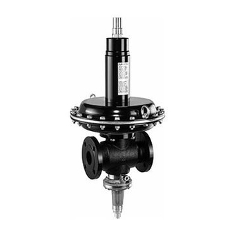
FRM 100025 - 100050
1. Target group
The target group of this manual is qualified personnel of the
gas safety and regulating technology. Due to their specialist
training, knowledge and experience, they should be capable
of evaluating the work assigned to them and recognising
possible dangers. Only they are permitted to carry out as-
sembly, commissioning, settings and maintenance on the
devices in compliance with the recognised rules for occupa-
tional safety.
2. Warnings
2.1 General warnings
The recognised occupational safety
rules and accident prevention regula-
tions must be observed and, if neces-
sary, personal protective measures must
be taken.
All adjustments and settings should only
be performed in accordance with the
instruction manuals of the connected
machines.
Never carry out work as long as gas
pressure or voltage is applied. Avoid
open fire. Please observe public regula-
tions.
Prior to assembly, the device must be
inspected for transport damage.
The device must not be exposed to open
fire. Protection against lightning strikes
must be guaranteed.
Connected line systems must be free
from dirt and contamination.
1 ... 64
Hang this instruction manual in a readily visible place
inside the installation room! Do not carry out any work
until you have read the safety instructions of this in-
struction manual and are qualified to do so.
Protection from environmental impacts
and weather conditions (corrosion, rain,
snow, icing, humidity (e.g. by conden-
sation), mould, UV radiation, harmful
insects, poisonous, corrosive solutions/
liquids (e.g. cutting and cooling fluids
must be guaranteed. Depending on the
installation site, it may be necessary to
take protective measures.
The device may only be operated in
compliance with the operating condi-
tions stated on the type plate.
The device must be protected from vi-
brations and mechanical impacts.
The device must not be used in areas
with increased seismic risk.
Explanation of the symbols
1, 2, 3,... =
•
=
),
Order of
action
Instruction
Advertisement
Table of Contents

Related Manuals for Dungs FRM 100025


Summary of Contents for Dungs FRM 100025
-
Page 1: Target Group
Instruction manual FRM 100025 - 100050 1. Target group The target group of this manual is qualified personnel of the gas safety and regulating technology. Due to their specialist training, knowledge and experience, they should be capable of evaluating the work assigned to them and recognising possible dangers. -
Page 2: Designated Use
2.2 Designated use The device is used in accordance with its designated use if • Use with dry and clean gases only, no aggressive media. the following instructions are observed: • Use only in compliance with the operating conditions • Use of the device in gas transport and gas distribution stated on the type plate. -
Page 3: Table Of Contents
4. Table of contents Target group Warnings General warnings Designated use Risks in case of misuse Approval/declaration of conformity Table of contents List of abbreviations Features Technical data Nomenclature Adjustment ranges Accuracy class / lock-up pressure class Selection of regulator springs Selection of SAV springs Type plate Function... -
Page 4: List Of Abbreviations
5. List of abbreviations Abbreviation Description Response pressure group of the upper response pressure Response pressure group of the lower response pressure Accuracy class Safety shutoff valve (without housing) Flow volume coefficient Nominal diameter Fail-open The firing valve moves automatically to the open position, if the main diaphragm or the auxiliary power required for the actuation of the firing valve fails Type: integral strength range Class A... -
Page 5: Features
6. Features 6.1. Technical data Technical data FRM … Device Spring-loaded medium pressure regulator according to EN 334 Type IS (integral strength range) Type of gas Family 1+2+3 Nominal diameters Connecting flanges PN 25 according to EN 1092-1 or ANSI 150 lbs (B16.5) Flange ANSI 1’’... -
Page 6: Nomenclature
6.2 Nomenclature Example ND SAV FRM 100025 ND / SAV ND Type Spring-loaded medium pressure regulator 100 … 10.000 mbar Nominal diameter DN 25 DN 40 DN 50 Pressure range, outlet pressure Low pressure Medium pressure High pressure Safety device... -
Page 7: Accuracy Class / Lock-Up Pressure Class
6.4 Accuracy class / lock-up pressure class Version Outlet pressure range Accuracy class [AC] Closing pressure FRM...ND 30-50 mbar AC 15 + 15 mbar 50-80 mbar AC 10 90-100 mbar AC 5 FRM...MD 90-120 mbar AC 15 + 25 mbar 120-180 mbar AC 10 180-420 mbar... -
Page 8: Selection Of Regulator Springs
6.5 Selection of regulator springs Adjustment range, outlet pressure W Spring colour Order Wire diameter Length Diameter Setpoint range [mbar] number [mm] [mm] [mm] Silver 270341 30-40 90-110 Green 270345 40-55 110-170 Yellow 270346 55-80 170-240 Blue 270347 80-100 240-330 Black 270348 330-420... -
Page 9: Type Plate
6.7 Type plate Regulator Abbrevia- Description tion Response pressure group of the upper response pressure Response pressure group of the lower response pressure Accuracy class Flow volume coefficient for natural gas Nominal diameter The mainvalve moves automatically to the open position, if the main diaphragm or the Fail-open auxiliary pressure required for the actuation of the main valve fails SAV type: integral strength range... -
Page 10: Function
7. Function The pressure regulator’s function is to keep the outlet pressure largely constant, independent of changes in the inlet pressure and/or in the flow volume. In the depressur- ised state the regulator is open. The pressure regulator complies with the requirements of EN 334 as gas pres- sure regulator with standard strength range (IS) and zero flow. -
Page 11: Dimensions
*Ermeto screw connection 12L: GE 12 - 1/4 with screw connection M16 for pipes 12 x 1.5 Type Order Dimensions Weight max. number [bar/kPa] [kg] FRM 100025 ND 270272 10 / 1000 29.5-1/2“G ⊘ ⊘ FRM 100025 MD 270273 10 / 1000 29.5-1/2“G ⊘... - Page 12 *Ermeto screw connection 12L: GE 12 - 1/4 with screw connection M16 for pipes 12 x 1.5 Type Order p max. Dimensions Weight number [bar/kPa] [kg] FRM 100025 ND/SAV ND 270275 10 / 1000 1070 29.5-1/2“G ⊘ ⊘ FRM 100025 MD/SAV MD 270276 10 / 1000 1070 29.5-1/2“G...
-
Page 13: Installation
9. Installation 9.1 General information • This device can only be installed in • Flanges on the inlet side and outlet side of the connecting compliance with the rules and stand line are parallel. ards applicable and in accordance with •... -
Page 14: Installation Instructions
9.2 Installation instructions • The installation must be carried according to the installa- • Maximum flow velocity in the stablisation section: tion scheme specified below. ≤ 30 m/s. • Install the safety shutoff valve in the flow direction (arrow/ • Use steel pipe impulse lines D= 12 x 1.5 housing). -
Page 15: Torque
Mounting position 9.3 Torque Use adequate tools! Tighten the screws crosswise! The device must not be used as lever. max. FRM... max. max. ⅜ ½ ¾ 1 ½ 2 ½ 1600 2400 5000 6000 7600 max. [Nm] t 10 s max. -
Page 16: Integrated Sav
10. Integrated SAV 10.1 Function SAV protects downstream fittings or lines against pres- sures that are too high or too low. As soon as the pre-set trip pressure falls below or exceeds a limit due to a fault, the SAV automatically interupts the gas flow. -
Page 17: Mounting On The Regulator
10.2 Mounting on the regulator 1. Loosen four hexagonal socket grub screws (M 5x8) of the ASE C using an internal hex key SW 2.5. 2. Remove the base plate A from the housing using a hook wrench 60-90. 3. Remove the O-ring B. 4. -
Page 18: Setting
11. Setting 11.1 Regulator setting Setting of the outlet pressure The regulator is set using the adjusting screw B. 1. Remove the protective cap A. 2. Turn the adjusting screw B using an open-ended wrench SW 24. 3. Turning clockwise: the preload of the setpoint spring is increased and the outlet pressure p is increased (+). -
Page 19: Sav Setting
11.2 SAV setting Switch-off setting in case of overpressure p 1. Remove the protective cap A. 2. Turn the external adjusting screw B using a socket wrench SW 22. 3. Turning clockwise: increase (+) in the upper shut down pressure p 4. -
Page 20: Calculation Example Of Set Values
11.3 Calculation example of set values Determination of the set values by means of a pressure graduation chart Selected regulator FRM 100025 MD / SAV MD Outlet pressure of the regulator p 200 mbar System-specific operating pressure downstream of the regulator p 500 mbar zul. -
Page 21: Exchange Of Regulator Springs
11.4 Replacement of regulator springs Release the setpoint spring E: unscrew the adjusting screw B counter-clockwise until it stops. Remove the protective cap A. (–) Unscrew the sealing cap C from the spring dome us- Remove the sealing cap C. ing a hinged hook wrench 90-155. - Page 22 Remove the spring washer D incl. ball. Remove the setpoint spring E from the spring dome F. 7. Insert a new spring with a suitable adjustment range 8. Reattach the spring washer D incl. ball on the spring. 9. Reinsert the sealing cap C in the spring dome F.
-
Page 23: Exchange Of Sav Springs
11.5 Replacement of SAV springs Remove the protective cap A. 11.5.1 Spring replacement W (–) Unscrew the adjusting spring B from the spring dome G using a tube/socket wrench SW 22. 23 … 64... -
Page 24: Spring Exchange W
1. Remove the spring E from the spring dome G. 2. Install the new spring. 3. Tighten the adjust- ing screw B and the washer D in the spring dome G using an open- ended wrench until the required spring preload is reached. - Page 25 1. Remove the spring F from the spring dome. 2. Install the new spring. 3. Tighten the adjust- ing screw C in the spring dome H us- ing an open-ended wrench SW 17 until the desired spring preload is reached. Screw on the protective cap A again.
-
Page 26: Commissioning And Decommissioning
12. Commissioning and decommissioning 12.1 General information Prior to commissioning • The performance data on the type plate correspond to the ordering data. • Prevent explosive gas-air mixture: the room atmosphere must be monitored through gas con- centration measuring devices for the detection of gas leakages. •... -
Page 27: Commissioning / Unlocking/ Control Of The Set Values
12.3 Commissioning / unlocking/ control of the set values 1. Slowly open the shutoff valve on the inlet side. The ball valve on the outlet side remains closed. 2. Monitor the pressure rise on the pressure gauge on the inlet side upstream of the device. - Page 28 6.0 Check of the upper shut-down pressure p 7.0 Check of the lower shut down pressure p 6.1 SBV installation on the outlet side: block the line 7.1 Release the pressure in the test section on the outlet upstream of the SBV. side until the operating pressure is reached.
-
Page 29: Recommissioning
The adjusting springs are not suitable for the application. Replace the adjusting springs. Replace the ASE or have it repaired by The valve disc is damaged or worn out. DUNGS. The valve seat is damaged. Replace the valve seat. The SAV can be activated, The movable parts are contaminated with foreign particles. -
Page 30: Troubleshooting
Fault on the regulator Possible causes Troubleshooting Check the gas installation upstream of the regu- The regulator contains no gas. lator. There is no gas. The SAV is closed. Unlock the SAV. The false setpoint spring is installed in the regulator. Replace the setpoint spring. -
Page 31: Maintenance
14. Maintenance 14.1 General information • The Pressure Equipment Direc- Pos. Designation tive (PED) requires the regulator to be Protective cap checked at regular intervals to ensure: Adjusting screw safety and correct functioning of the Sealing cap device, high long-term utilisation ratios, resulting in minimum environmental Spring washer with ball impact. - Page 32 W ... 32 …64...
-
Page 33: Maintenance Instructions Of The Regulator
14.2 Maintenance instructions of the regulator 14.2.1 Preparation (–) 1. Loosen the impulse line and the vent line and remove them. 4. Unscrew the sealing cap C from the spring dome 2. Remove the protective cap A. using a jointed hook wrench 90-155. 3. - Page 34 FRM...ND FRM...MD/HD Remove the upper diaphragm shell F. Remove the upper diaphragm shell F. FRM...HD FRM...HD Remove the O-ring H (HD version only). Remove the reducing washer I (HD version only). 34 …64...
- Page 35 FRM...MD/HD FRM...ND Loosen the nut J (M 8) using an open-ended wrench SW 13. Loosen the nut J (M 8) using an open-ended wrench SW 13. FRM...MD/HD FRM...ND Remove the spring washer K. Remove the spring washer K. 35 … 64...
- Page 36 FRM...ND FRM...MD/HD Remove the safety spring L. Remove the safety spring L. FRM...MD/HD FRM...ND Remove the working diaphram M from the guide rod Remove the working diaphram M from the guide rod N and check for signs of damage or wear. If neces- N and check for signs of damage or wear.
-
Page 37: Replacement Of The Control Plate / Valve Seat
14.2.3 Replacement of the control plate / valve seat Remove the lower diaphragm shell O from the housing X. To do this, the diaphragm shell O has to be turned carefully. 4 Loosen the screws Y. Remove the O-ring Q from the lower diaphragm shell O. 37 …... - Page 38 Remove the control plate S from the control plate Remove the assembly of the control plate S incl. the sleeve U and check it for damage. If necessary, sleeve U from the housing X. replace the control plate S incl. the sleeve U. Remove the O-ring T from the housing X.
- Page 39 If necessary, replace the valve seat V: screw out the valve seat V from the housing X by using a socket wrench. Tighten the new valve seat V with the new O-ring W (maintenance set 4) in the housing X. Place the new O-ring T (maintenance kit 3 or 5) in Insert the control plate S with the sleeve U (mainte- the turned groove in the housing X.
- Page 40 Insert the new O-ring Q (maintenance kit 3, 4 or 5) Make sure that the connection pin R 45° is oriented in the turned groove in the lower diaphragm shell O opposite to the direction of the flow (non-aligned!) using grease if necessary to hold it in place. Put the diaphragm shell O in position: Secure the lower diaphragm shell O using the lower diaphragm disc P (to do this, the diaphragm disc is...
- Page 41 When the connection pin R is locked in the lever sys- tem Z, both middle lever arms are pushed upwards ( ). To do this, ( ) push the lower diaphragm disc P downwards. Attention: Risk of crushing! 41 … 64...
- Page 42 Reinsert the working diaphragm M on the guide rod N. Put on the safety spring L and the spring washer K. Screw on the nut J (M 8). Tighten to the stop using an open-ended screw Fix the diaphram housing O by tightening the 4 SW 13.
-
Page 43: Maintenance Instructions Of The Sav
14.3 Maintenance instructions of the SAV ASE...ND ASE...MD/HD 43 … 64... - Page 44 Pos. Designation Diaphragm shell Push rod O-ring of the diaphragm shell Lower diaphragm disc Working diaphragm Setpoint spring of the lower shut-down pressure Upper diaphragm disc (HD version only) Allen screw, 6 pieces Spring dome ASE Over pressure adjustment nut Under pressure adjustment nut Protective cap Housing ASE...
-
Page 45: Preparation
14.3.1 Preparation (–) (–) 1. Remove the impulse and vent lines. 2. Remove the protective cap L. 3. Release the setpoint springs at the adjusting screws J and K. 13.3.2 Removing the ASE from the housing Loosen four hexagonal Remove the ASE Q from socket grub screws (M5x8) the housing using a hook using an internal hex key... -
Page 46: Check / Replacement Of The Working Diaphragm, Md/Hd Version
Remove the ASE Q. 14.3.3 Check / replacement of the working diaphragm, MD/HD version Loosen the six Allen screws H (M5) using an internal hex key SW 4. Remove the cover I of the ASE Q. 46 …64... - Page 47 Remove the thin diaphragm ring G (HD version only). Rremove the under pressure set point spring F from push rod B and then clean it. Remove the working diaphragm E. Remove the thick diaphragm ring D. 47 … 64...
- Page 48 Remove the O-ring C and clean the push rod B. Insert the new O-ring C (maintenance set 7) in the turned groove of the diaphragm shell A. Reinsert the diaphragm ring D with the turned groove upwards. Check the state of the working diaphragm E. If necessary, replace with a new working diaphragm (maintenance set 2).
-
Page 49: Check / Replacement Of The Working Diaphragm, Nd Version
14.3.4 Check / replacement of the working diaphragms, ND version Loosen the six Allen screws H (M5) using an internal hex key SW 4. Remove the cover I of the ASE Q. Remove the setpoint spring F for lower shut-down pressure from the push rod B and then clean it. -
Page 50: Mounting Of The Ase On The Housing
Remove the diaphragm ring D. Remove the O-ring C. Clean the push rod B. Insert the new O-ring C (maintenance set 7) in the turned groove of the diaphragm shell K. Reinsert the diaphragm ring D with the turned groove upwards. Check the state of the working diaphragm E. -
Page 51: Necessary Tools
14.4 Required tools Order no. 271170 Wrench size Pressure Work step Tool designation rating DN 25 DN 40 DN 50 Loosen the pulse lines. Open-ended spanner (A) ND/MD/HD SW 24 SW 24 SW 24 Tube/socket wrench (B) SW 17 SW 17 SW 17 Release the setpoint springs. - Page 52 Regulator Wrench size Pressure Work step Tool designation rating DN 25 DN 40 DN 50 Loosen the pulse lines. Open-ended spanner (A) ND/MD/HD SW 24 SW 24 SW 24 Open-ended spanner (A) SW 24 SW 24 SW 24 Release the setpoint springs. ND/MD/HD Hinged hook wrench (D) 90-155...
-
Page 53: Leakage Test
14.5 Leakage test After maintenance or repair work, the device must be checked for internal and external leakages. 1. Test gases of the leakage test: air or inert gases. 2. Upstream and downstream shutoff valves must be closed. 3. Test pressure > blow-off pressure SBV: block the line upstream of the SBV. -
Page 54: Spare Parts
15. Spare parts 54 …64... -
Page 55: List Of Spare Parts Of The Regulator
15.1 List of spare parts of the regulator Spare part Version Order number Spare part / image Protective FRM 100025-100050 270396 FRM 100025-100050 ND 270384 Working diaphragm FRM 100025-100050 MD 270385 with O-ring FRM 100025-100050 HD 270386 FRM 100025 ND... -
Page 56: List Of Spare Parts Of The Sav
15.2 List of spare parts of SAV Spare part Version Order number Spare part / image SAV 100025-100050 ND/MD/HD Protective on request SAV 6010-6020 ND/MD/HD SAV 100025-100050 ND SAV 6010-6020 ND on request Working diaphragm SAV 100025-100050 MD with O-ring SAV 6010-6020 MD on request SAV 100025-100050 HD... -
Page 57: Complete Regulator Sets
15.3 Complete regulator sets Order Version Contents number FRM 100025 ND 271093 FRM 100025 MD 271094 FRM 100025 HD 271095 FRM 100040 ND 271096 FRM 100040 MD 271097 FRM 100040 HD 271098 57 … 64... - Page 58 Order Version Contents number FRM 100050 ND 271095 FRM 100050 MD 271098 FRM 100050 HD 271101 58 …64...
-
Page 59: Storage Conditions
15.3 Storage conditions Basically, DIN 7716 (standards for storage, maintenance • Ozone and cleaning of rubber products) applies to the storage of • Stress conditions of the components diaphragms and O-rings. Proper storage The ageing process mostly depends on • Storage temperature between 5°... -
Page 60: Natural Gas Flow Volume Table
16.1 Natural gas flow volume tables FRM 100025 … DN 25 - max. flow volume [Nm /h] natural gas of density 0.81 kg/m³ (AC 10) FRM ... [bar] 0,03 0,05 0,075 0,15 0,25 0,35 0,75 1,25 [bar] 0,75 1039 1052... -
Page 61: Air Flow Volume Tables
1608 1707 1868 1967 2289 1893 2079 2079 2351 2895 3106 16.2 Air flow volume tables FRM 100025... DN25 - max. air flow volume [Nm /h] (AC 10) FRM ... [bar] 0,03 0,05 0,075 0,15 0,25 0,35 0,75 1,25 [bar]... - Page 62 FRM 100040... DN40 - max. air flow volume [Nm /h] (AC 10) FRM... [bar] 0,03 0,05 0,075 0,15 0,25 0,35 0,75 1,25 [bar] 0,75 1020 1030 1030 1100 1150 1300 1300 1300 1030 1040 1330 1420 1430 1500 1030 1020 1100 1130 1140...
-
Page 63: Valve Flow Volume Coefficient K
1.00 1.00 16.3 Valve flow volume coefficient K Type -value FRM 100025... FRM 100040... FRM 100050... 1150 The valve flow volume coefficient K f FRM is equal to the flow volume for a completely open firing valve with an absolute inlet pressure of p = 2.01325 bar and absolute outlet pressure of p... - Page 64 N/A not applicable We reserve the right to make modifications in the course of technical development. Head of office and factory Subsidiary Karl Dungs Limited Karl Dungs GmbH & Co. KG 18, Liberty Way Karl-Dungs-Platz 1 Attleborough Fields Ind. Est. D-73660 Urbach,...
Need help?
Do you have a question about the FRM 100025 and is the answer not in the manual?
Questions and answers