Table of Contents
Advertisement
Quick Links
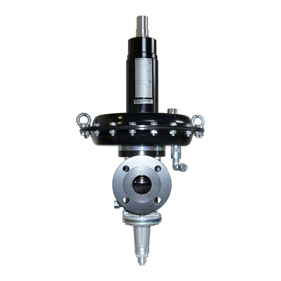
Mitteldruckregler FRM
Medium Pressure
Regulator FRM
Direkt wirkendes Druckregelgerät nach
EN 334 mit einstellbarer Sollwertfeder
und modular anbaubarem Sicherheits-
absperrventil nach EN 14382
Direct acting pressure regulator with
adjustable setpoint springs and modular
mounted safety relief valve (SAV)
In compliance with EN334 and EN14382
Advertisement
Chapters
Table of Contents

Related Manuals for Dungs FRM Series


Summary of Contents for Dungs FRM Series
- Page 1 Mitteldruckregler FRM Medium Pressure Regulator FRM Direkt wirkendes Druckregelgerät nach EN 334 mit einstellbarer Sollwertfeder und modular anbaubarem Sicherheits- absperrventil nach EN 14382 Direct acting pressure regulator with adjustable setpoint springs and modular mounted safety relief valve (SAV) In compliance with EN334 and EN14382...
- Page 2 400-1500 mbar AC 5 SG 10 150-2500 mbar AG 5 500-4000 mbar AG 5 *Genauigkeitsklasse / Schließdruckgruppe nach EN 334 *Accuracy class / Lock-up pressure class according to EN 334 = 80-180 mbar: AC 10 = 180-420 mbar: AC 5 Dungs...
- Page 3 Medium Pressure Regulator FRM NEU! NEW! Federbelasteter Regler Mitteldruck nach EN 334 Sicherheitsabsperrventil nach EN 14382, Klasse A Bauart IS (einheitlicher Festigkeitsbereich) Bauart Gasart Familie 1+2+3 Ansprechzeit < 2 s Nennweiten Anschlussflansche PN 25 nach EN 1092-1 Einstellbereich unten W 10 mbar bis 2500 mbar (1-250 kPa) Flansche DN 25 40...
- Page 4 Blau / Blue 30 – 115 Lila / Purple 80 – 400 Rosa / Pink 800 – 2500 Karl Dungs GmbH & Co. KG Siemensstraße 6 – 10 73660 Urbach, Germany Telefon +49 7181 804-0 Telefax +49 7181 804-166 info@dungs.com www.dungs.com...
- Page 5 Mitteldruckregler Mitteldruckregler Typ FRM Direkt wirkendes Druckregelgerät mit einstellbarer Sollwertfeder und modular anbaubarem Sicherheitsabsperrventil (SAV) Entspricht der EN 334 und EN 14382 • Eingangsdrücke bis 10 bar (1000 kPa) • Große Durchflussleistung • Stabile, exakte und feinfühlige Regelung des Reglerausgangsdrucks •...
- Page 6 Inhaltsverzeichnis FRM Anwendung Zulassung Technische Daten 4 + 5 Druckabgriffe Nomenklatur Einstellbereiche Federauswahl Regler Federauswahl SAV Einbaumaße 11 + 12 Funktion Schnittbild FRM / SAV 13 + 14 Geräteauswahl / Durchflusstabellen 15 - 18 Auslegungsbeispiel Adressen 2 ... 20 FRM Ÿ Edition 10.15 Ÿ 270 048...
- Page 7 Anwendung Zulassung Federbelastetes, vordruck- Für alle Aufgaben der Druckregelung EG-Baumusterprüfbescheinigung ausgeglichenes Druckregelgerät an Gasbrennern und Gasgeräten im mit einstellbarer Sollwertfeder zur nach EG - Druckgeräterichtlinie. Industrie- und Heizungsbereich. Ein- Regelung des Reglerausgangs- satz auch in der kommunalen und druckes. Externer Abgriff des gewerblichen Gasversorgung.
- Page 8 Technische Daten FRM Federbelasteter Regler Mitteldruck nach EN 334 Bauart IS (einheitlicher Festigkeitsbereich) Gasart Familie 1+2+3 Nennweiten Anschlussflansche PN 25 nach EN 1092-1 Flansche DN 25 40 Max. Eingangsdruck 10 bar (1000 kPa) Ausgangsdruckbereich 30 mbar bis 1500 mbar (3-150 kPa) Minimaler Differenzdruck (ND) 270 mbar (27 kPA) Minimaler Differenzdruck (MD)
- Page 9 Technische Daten SAV Sicherheitsabsperrventil nach EN 14382, Klasse A Bauart Ansprechzeit < 2 s Einstellbereich unten W 10 mbar bis 2500 mbar (1-250 kPa) Einstellbereich oben W 40 mbar bis 4000 mbar (4-400 kPa) Werkstoffe Stellgliedgehäuse: Gusseisen GGG 50 Membrangehäuse: Aluminium Membranen: Inhaltsverzeichnis...
- Page 10 Druckabgriffe Anschluss Atmungsleitung Regler, G 1/2 ISO 228 Anschluss externe Impulsleitung Regler, Ermetoverschraubung GE 12- 1/4 für Rohre 12 x 1,5 Anschluss externe Impulsleitung SAV, Ermetoverschraubung GE 12- 1/4 für Rohre 12 x 1,5 Anschluss Atmungsleitung SAV, G 1/4 ISO 228 Inhaltsverzeichnis 6 ...
- Page 11 Nomenklatur Beispiel FRM 100025 ND / SAV ND SAV ND Federbelasteter Regler Mitteldruck 100 … 10 000 mbar Nennweite DN 25 DN 40 DN 50 Druckbereiche Ausgangsdruck Niederdruck Mitteldruck Hochdruck Sicherheitseinrichtung Integriertes Sicherheitsabsperrventil Druckbereiche Auslösedruck Niederdruck Mitteldruck Hochdruck Inhaltsverzeichnis 7 ... 20 FRM Ÿ...
- Page 12 Einstellbereiche Aus- Genau- Schließ- Ausgangs- Unterer Schaltpunkt Oberer Schaltpunkt schluss füh- igkeits- druck- druckbereich rung klasse* gruppe* [AC] [SG] FRM 100025 ND DN 25 AC 10 SG 20 30-100 mbar FRM 100025 MD DN 25 AC 5/10** SG 20 90-420 mbar FRM 100025 HD DN 25 AC 5...
- Page 13 Federauswahl Regler Der Ansprechdruck resultiert aus Einstellbereich Ausgangsdruck W der Kraft der eingebauten Ein- Federfarbe Bestell- Drahtdurchmesser Länge Durchmesser Sollwertbereich [mbar] stellfeder und der Gewichtskraft Nummer [mm] [mm] [mm] der beweglichen Teile. Durch den Wechsel der Sollwertfeder 1 ist es Silber 270341 30-40...
- Page 14 Federauswahl SAV Der Ansprechdruck resultiert Spezifischer Einstellbereich Druckmangel W aus der Kraft der eingebauten Federfarbe Bestell- Drahtdurchmesser Länge Durchmesser Sollwertbereich [mbar] Einstellfeder. An der äußeren Nummer [mm] [mm] [mm] Feder 1 des Messwerks wird der oberer Ansprechdruck (Über- Weiß 270353 10,0 10-32 druck) eingestellt.
- Page 15 Einbaumaße FRM Bestell- Einbaumaße Gewicht max. Nummer [bar / kPa] [kg] FRM 100025 ND 270272 10 / 1000 FRM 100025 MD 270273 10 / 1000 FRM 100025 HD 270274 10 / 1000 FRM 100040 ND 270278 10 / 1000 FRM 100040 MD 270279 10 / 1000 FRM 100040 HD...
- Page 16 Einbaumaße FRM mit SAV Bestell- Einbaumaße Gewicht max. Nummer [bar / kPa] [kg] FRM 100025 ND/SAV ND 270275 10 / 1000 1070 FRM 100025 MD/SAV MD 270276 10 / 1000 1070 FRM 100025 HD/SAV HD 270277 10 / 1000 1080 FRM 100040 ND/SAV ND 270281 10 / 1000...
- Page 17 Schnittbild FRM Funktion Druckregelgerät in Offenstellung Wirkungsweise nach dem Kräftevergleichs- Bei Anstieg des Ausgangsdrucks, steigt in der prinzip zwischen der Kraft: unteren Membranschale 3 die Kraft auf die • der einstellbaren Sollwertfeder, Arbeitsmembran 6. • der vorgegebenen Gegenfeder, Die Arbeitsmembran 6 wird dadurch nach oben •...
- Page 18 Schnittbild SAV Funktion Gerät in Geschlossenstellung Kammer 4 ist über eine Impulsleitung mit dem Ausgangsdruck verbunden. Auf die Arbeitsmem- bran 5 wirkt der zu kontrollierende Druck. Die Kraft der Sollwertfedern 7 und 8 wirkt als Gegen- kraft. Bei Kräfteungleichgewicht (Überdruck oder Druckmangel) löst das SAV aus und sperrt die Gaszufuhr.
- Page 19 Durchflusstabellen Geräteauswahl Die Auswahl erfolgt mit Hilfe der nachstehen- FRM 100025... DN25 - max. Durchfluss Luft (AC 10) den Durchflusstabellen. Der angegebene maximale Volumenstrom bezieht sich auf Luft FRM ... mit einer Dichte von 1,24 kg/m bei 15 °C im [bar] Normzustand.
- Page 20 Durchflusstabellen Geräteauswahl FRM 100040... DN40 - max. Durchfluss Luft (AC 10) FRM... [bar] 0,03 0,05 0,075 0,15 0,25 0,35 0,75 1,25 [bar] 0,75 1020 1030 1030 1100 1150 1300 1300 1300 1030 1040 1330 1420 1430 1500 1030 1020 1100 1130 1140 1410...
- Page 21 Durchflusstabellen Geräteauswahl FRM 100050... DN50 - max. Durchfluss Luft (AC 10) FRM... [bar] 0,03 0,05 0,075 0,15 0,25 0,35 0,75 1,25 [bar] 0,75 1000 1100 1040 1080 1080 1120 1030 1180 1090 1200 1240 1240 1300 1010 1120 1260 1040 1200 1320 1380...
- Page 22 Berechnung der Gasarten ° ° V Gasart Dichte verwendetes Gas Luft [kg/m Erdgas 0.81 0.65 1.24 Dichte Luft spez. Gewicht des verwendeten Gases Stadtgas 0.58 0.47 1.46 Flüssiggas 2.08 1.67 0.77 Luft 1.24 1.00 1.00 Inhaltsverzeichnis 18 ... 20 FRM Ÿ Edition 10.15 Ÿ 270 048 ←...
- Page 23 Auslegungsbeispiel Geräteauswahl FRM 100025... DN25 - max. Durchfluss Luft (AC 10) FRM 100040... DN40 - max. Durchfluss Luft (AC 10) FRM ... FRM... Anlagedaten [bar] [bar] 0,03 0,05 0,075 0,15 0,25 0,35 0,75 1,25 0,03 0,05 0,075 0,15 0,25 0,35 0,75 1,25 Medium: Erdas...
- Page 24 Karl Dungs GmbH & Co. KG Telefon +49 (0)7181-804-0 Siemensstraße 6-10 Telefax +49 (0)7181-804-166 D-73660 Urbach, E-mail info@dungs.com Germany Internet www.dungs.com Änderungen, die dem technischen Fortschritt dienen, vorbehalten. Inhaltsverzeichnis 20 ... 20 FRM Ÿ Edition 10.15 Ÿ 270 048 ←...
- Page 25 Medium Pressure Regulator Medium pressure regulator Type FRM Direct acting pressure regulator with adjustable setpoint springs and modularly mountable safety shutoff valve (SSD) In compliance with EN 334 and EN 14382 • Inlet pressures up to 10 bar (1000 kPa) •...
- Page 26 Table of contents FRM Application Approval Technical data 4 + 5 Pressure taps Nomenclature Adjustment range Selection of regulator springs Selection of SSD springs Dimensions 11 + 12 Function Sectional drawing FRM/SSD 13 + 14 Device selection / flow volume tables 15 - 18 Design example Contact details...
- Page 27 Application Approval Spring-loaded, pressure com- Pressure regulation of industrial gas EC type-examination certificate according pensating regulator with adjusta- burners and gas heating appliances. ble setpoint springs for regulation to the EC pressure installation directive. Also for installation in the municipal of the regulator outlet pressure.
- Page 28 Technical Data FRM Spring-loaded medium pressure regulator in compliance with EN334 Type IS (standard strength range) Type of gas Family 1+2+3 Nominal diameters Connecting flange PN 25 according to EN1092-1 Flanges DN 25 40 Max. inlet pressure 10 bar (1000 kPa) Outlet pressure range 30 mbar up to 1500 mbar (3-150 kPa) Minimum differential pressure (ND)
- Page 29 Technical Data SSD Safety shut-off valve in compliance with EN14382, class A Type Response time < 2 s Lower adjustment range W 10 mbar up to 2500 mbar (1-250 kPa) Upper adjustment range W 40 mbar up to 4000 mbar (4-400 kPa) Materials Main body housing: cast iron GGG 50...
- Page 30 Pressure taps Vent line connection of the regulator, G 1/2 ISO 228 External impulse line connection of the regulator, Ermeto screw connection GE 12- 1/4 for tubes 12 x 1.5 External impulse line connection of the SSD, Ermeto screw connection GE 12- 1/4 for tubes 12 x 1.5 Vent line connection of the SSD, G 1/4 ISO 228...
- Page 31 Nomenclature Example FRM 100025 ND / SSD ND Spring-loaded medium pressure regulator Type 100 … 10 000 mbar Nominal diameter DN 25 DN 40 DN 50 Pressure range, outlet pressure Low pressure Medium pressure High pressure Safety device Integrated shut-off valve Pressure range, Low pressure trip pressure...
- Page 32 Adjustment range Type Con- Ver- Accuracy Lock-up Outlet pres- Under-pressure Over pressure nection sion class* pressure sure range W monitoring SSD monitoring SSD [AC] class* [SG] FRM 100025 ND DN 25 AC 10 SG 20 30-100 mbar FRM 100025 MD DN 25 AC 5/10** SG 20...
- Page 33 Selection of regulator springs The response pressure results Specific set range, outlet pressure W from the force of the installed Spring colour Order Wire diameter Length Diameter Setpoint range [mbar] adjusting spring and the weight number [mm] [mm] [mm] force of the movable parts. By changing the setpoint spring 1, Silver 270341...
- Page 34 Selection of SSD springs The response pressure results from Specific set range, underpressure W the force of the installed adjusting Spring colour Order number Wire diameter [mm] Length [mm] Diameter [mm] Setpoint range [mbar] spring. The upper response pres- sure (overpressure) is set on the external spring 1 of the measure- White 270353...
- Page 35 Dimensions FRM Type Order Dimensions Weight max. number [bar / kPa] [kg] FRM 100025 ND 270272 10 / 1000 FRM 100025 MD 270273 10 / 1000 FRM 100025 HD 270274 10 / 1000 FRM 100040 ND 270278 10 / 1000 FRM 100040 MD 270279 10 / 1000...
- Page 36 Dimensions FRM with SSD Type Order Dimensions Weight max. number [bar / kPa] [kg] FRM 100025 ND/SSD ND 270275 10 / 1000 1070 FRM 100025 MD/SSD MD 270276 10 / 1000 1070 FRM 100025 HD/SSD HD 270277 10 / 1000 1080 FRM 100040 ND/SSD ND 270281...
- Page 37 Sectional drawing FRM Function Pressure regulator in open position Mode of operation according to the force In case of an increase of the outlet pressure, the comparison principle between the force: working diaphram 6 is pushed upwards, until the • of the adjustable setpoint spring, force of the setpoint spring 8 is equal to that of the •...
- Page 38 Sectional drawing SSD Function Device in the closed position Chamber 4 is connected to the outlet pressure via an impulse line. The pressure being monitored acts on the working diaphragm 5. The force of the setpoint springs 7 and 8 acts as counterforce. In case of an unbalance of forces (overpressure or underpressure), the SSD is actuated and the gas supply is blocked.
- Page 39 Flow rate tables Device selection The following flow rate tables can be used to FRM 100025... DN25 - max. air flow volume (AC 10) select the device. The maximum indicated vol- ume flow refers to the air with a standard densi- FRM ...
- Page 40 Flow rate tables Device selection FRM 100040... DN40 - max. air flow volume (AC 10) FRM... [bar] 0,03 0,05 0,075 0,15 0,25 0,35 0,75 1,25 [bar] 0,75 1020 1030 1030 1100 1150 1300 1300 1300 1030 1040 1330 1420 1430 1500 1030 1020...
- Page 41 Flow volume tables Device selection FRM 100050... DN50 - max. air flow volume (AC 10) FRM... [bar] 0,03 0,05 0,075 0,15 0,25 0,35 0,75 1,25 [bar] 0,75 1000 1100 1040 1080 1080 1120 1030 1180 1090 1200 1240 1240 1300 1010 1120 1260...
- Page 42 Calculation of gas types ° ° V Type of gas Spec. used gas Wgt. [kg/m Natural gas 0.81 0.65 1.24 air density spec. weight of the gas used City gas 0.58 0.47 1.46 2.08 1.67 0.77 1.24 1.00 1.00 Table of contents 18 ...
- Page 43 Design example Device selection FRM 100025... DN25 - max. air flow volume (AC 10) FRM 100040... DN40 - max. air flow volume (AC 10) FRM ... FRM... System data [bar] [bar] 0,03 0,05 0,075 0,15 0,25 0,35 0,75 1,25 0,03 0,05 0,075 0,15...
- Page 44 Head of Office and Factory Karl Dungs GmbH & Co. KG Siemensstr. 6-10 D-73660 Urbach, Germany Phone +49 (0)7181-804-0 +49 (0)7181-804-166 e-mail: info@dungs.com Internet: www.dungs.com Subject to technical modification in the interest of technical progress. Table of contents 20 ... 20 FRM Ÿ...
- Page 45 Gebrauchsanleitung FRM 100025 - 100050 1. Zielgruppe Zielgruppe dieser Anleitung sind Fachkräfte der Gas- Sicherheits- und Regelungstechnik, befähigte Per- sonen oder die von Ihnen unterwiesenen Personen. Sie können aufgrund ihrer fachlichen Ausbildung, Kennt- nisse und Erfahrungen sowie Kenntnis der einschlägigen Bestimmungen die ihnen übertragenen Arbeiten beur- teilen und mögliche Gefahren erkennen.
- Page 46 2.2 Bestimmungsgemäßer Gebrauch Die bestimmungsgemäße Verwendung des Gerätes ist • Einsatz nur mit trockenen und sauberen Gasen, keine gegeben, wenn die nachfolgenden Hinweise beachtet aggressiven Medien. werden: • Einsatz nur unter Einhaltung der auf dem Typenschild • Einsatz des Gerätes in Gastransport- und Gasvertei- angegebenen Betriebsbedingungen.
-
Page 47: Table Of Contents
4. Inhaltsverzeichnis Zielgruppe Warnhinweise Allgemeine Warnhinweise Bestimmungsgemäßer Gebrauch Risiken bei Missbrauch Zulassung/Konformitätserklärung Inhaltsverzeichnis Abkürzungsverzeichnis Merkmale Technische Daten Nomenklatur Einstellbereiche Genauigkeitsklasse / Schließdruckgruppe Federauswahl Regler Federauswahl SAV Typenschild Funktion Einbaumaße Einbau/Installation Allgemeine Hinweise Einbaubeschreibung Drehmomente Integriertes SAV 10.1 Funktion 10.2 Anbau an das Regelgerät Einstellung 11.1 Einstellung Regler... -
Page 48: Abkürzungsverzeichnis
5. Abkürzungsverzeichnis Abkürzung Beschreibung Ansprechdruckgruppe des oberen Ansprechdrucks Ansprechdruckgruppe des unteren Ansprechdrucks Genauigkeitsklasse Sicherheitsabsperreinrichtung (ohne Gehäuse) Durchflusskoeffizient Nennweite Fail-open Stellglied, bewegt sich automatisch in die Offenstellung, wenn die Hauptmembran oder die erforderliche Hilfsenergie zum Antrieb des Stellglieds ausfällt Bauart: einheitlicher Festigkeitsbereich Klasse A Funktionsklasse: SAV wirkt bei Schaden an der Vergleichsmembran oder bei Ausfall der Hilfsenergie schließend... -
Page 49: Merkmale
6. Merkmale 6.1 Technische Daten Technische Daten FRM … Gerät Federbelasteter Regler Mitteldruck nach EN 334 Bauart Gasart Familie 1+2+3 Nennweiten Anschlußflansche PN 25 nach EN 1092-1 Flansch Zulässige Druckbeanspruchung 10 bar (1000 kPa) Max. Eingangsdruck 10 bar (1000 kPa) Ausgangsdruckbereich 30 - 1500 mbar (3-150 kPa) Minimaler Differenzdruck... -
Page 50: Nomenklatur
6.2 Nomenklatur Beispiel FRM 100025 ND / SAV ND Federbelasteter Regler Mitteldruck 100 … 10 000 mbar Nennweite DN 25 DN 40 DN 50 Druckbereiche Ausgangsdruck Niederdruck Mitteldruck Hochdruck Sicherheitseinrichtung Integriertes Sicherheitsabsperrventil Druckbereiche Auslösedruck Niederdruck Mitteldruck Hochdruck 6.3 Einstellbereiche Aus- Genau- Schließ- Ausgangs-... -
Page 51: Genauigkeitsklasse / Schließdruckgruppe
6.4 Genauigkeitsklasse / Schließdruckgruppe Ausführung Ausgangsdruckbereich Genauigkeitsklasse [AC] Schließdruck FRM...ND 30-50 mbar AC 15 + 15 mbar 50-80 mbar AC 10 80-100 mbar AC 5 FRM...MD 90-120 mbar AC 15 + 25 mbar 120-180 mbar AC 10 180-420 mbar AC 5 FRM...HD 400-450 mbar AC 10... -
Page 52: Federauswahl Regler
6.5 Federauswahl Regler Einstellbereich Ausgangsdruck W Federfarbe Bestell- Drahtdurchmesser Länge Durchmesser Sollwertbereich [mbar] Nummer [mm] [mm] [mm] Silber 270341 30-40 90-110 Grün 270345 40-55 110-170 Gelb 270346 55-80 170-240 Blau 270347 50-100 240-330 Schwarz 270348 330-420 400-580 Lila 270349 10,0 560-850 Orange 270350... -
Page 53: Typenschild
6.7 Typenschild Regler Abkürzung Beschreibung Ansprechdruckgruppe des oberen Ansprechdrucks Ansprechdruckgruppe des unteren Ansprechdrucks Genauigkeitsklasse Durchflusskoeffizient bezogen auf Erdgas Nennweite Fail-open Stellglied, bewegt sich automatisch in die Offenstellung, wenn die Hauptmembran oder die erforderliche Hilfsenergie zum Antrieb des Stellglieds ausfällt Bauart des SAV: einheitlicher Festigkeitsbereich Klasse A Funktionsklasse: SAV wirkt bei Schaden an der Vergleichsmembran oder bei Ausfall der Hilfsenergie schließend... -
Page 54: Funktion
7. Funktion Das Druckregelgerät hat die Aufgabe, den Ausgangs- druck trotz schwankendem Eingangsdruck oder/und schwankendem Durchfluss konstant zu halten. In druck- losem Zustand ist das Regelgerät geöffnet. Das Druck- regelgerät entspricht den Anforderungen der EN 334 als Gas-Druckregelgeräte mit einheitlichem Festigkeitsbe- reich (IS) und Nullabschluss. -
Page 55: Einbaumaße
8. Einbaumaße FRM... * Ermeto-Verschraubung 12L: GE 12 - 1/4 mit Verschraubung M16 für Rohre 12 x 1,5 Bestell- Einbaumaße Gewicht max. Nummer [bar/kPa] [kg] FRM 100025 ND 270272 10 / 1000 29,5-1/2“G ⊘ ⊘ FRM 100025 MD 270273 10 / 1000 29,5-1/2“G ⊘... - Page 56 FRM... / SAV * Ermeto-Verschraubung 12L: GE 12 - 1/4 mit Verschraubung M16 für Rohre 12 x 1,5 Bestell- p max. Einbaumaße Gewicht Nummer [bar/kPa] [kg] FRM 100025 ND/SAV ND 270275 10 / 1000 1070 29,5-1/2“G ⊘ ⊘ FRM 100025 MD/SAV MD 270276 10 / 1000 1070...
-
Page 57: Einbau/Installation
9. Einbau / Installation 9.1 Allgemeine Hinweise • Einbau des Gerätes nur nach dem schlag vermeiden. gültigen Regelwerk und in Überein- • Leistungsdaten des Typenschild stimmen mit den stimmung mit den örtlichen Vor- Bestelldaten überein. schriften, ggf. erforderliche Geneh- • Eingangsseitige und ausgangsseitige Flansche der migungen einholen. -
Page 58: Einbaubeschreibung
9.2 Einbaubeschreibung • Installation nach dem unten angegebenen Einbau- • Maximale Strömungsgeschwindigkeit in der Beruhi- schema durchführen. gungsstrecke: ≤ 30 m/s. • Einbau des Sicherheitsabsperrventils in Fließrichtung • Ausführung Impulsleitungen: Stahlrohr D= 12 x 1,5 (Pfeil/Gehäuse). • Ansammlung von Kondensat verhindern: Impulsleitun- •... -
Page 59: Drehmomente
Einbaulage 9.3 Drehmomente Geeignetes Werkzeug einsetzen! Schrauben kreuzweise anziehen! Gerät darf nicht als Hebel benutzt werden. max. FRM... max. max. ⅜ ½ ¾ 1 ½ 2 ½ 1600 2400 5000 6000 7600 max. [Nm] t 10 s max. [Nm] t 10 s Max. -
Page 60: Integriertes Sav
10. Integriertes SAV 10.1 Funktion Das SAV schützt nachgeschaltete Armaturen und Lei- tungssysteme gegen zu hohen oder zu niedrigen Druck. Es unterbricht automatisch den Gasfluss sobald der voreingestellte Auslösedruck aufgrund einer Störung über- oder unterschritten wird. Unter normalen Betriebs- bedingungen ist das SAV geöffnet. Wenn die Ausgangsseite des Gasdruckreglers und/ oder der anschließende Leitungsabschnitt mit seiner Ausrüstung bis zur Gasverbrauchseinrichtung nicht für... -
Page 61: Anbau An Das Regelgerät
10.2 Anbau an das Regelgerät 1. Vier Innensechskant-Gewindestifte (M 5x8) der ASE C mit Innensechskantschlüssel SW 2,5 lösen. 2. Bodenplatte A mit Hakenschlüssel 60-90 aus dem Gehäuse ausschrauben. 3. O-Ring B entfernen. 4. Neuen O-Ring B aus dem Wartungsset 6 auf der ASE C positionieren. -
Page 62: Einstellung
11. Einstellung 11.1 Einstellung Regler Einstellung des Ausgangsdrucks Die Einstellung des Reglers erfolgt durch Verstellen der Einstellschraube B. 1. Schutzkappe A entfernen. 2. Einstellschraube B mit Gabelschlüssel SW 24 drehen. 3. Drehung im Uhrzeigersinn: Erhöht die Vorspannung der Sollwertfeder und vergrößert (+) damit den Aus- gangsdruck p 4. -
Page 63: Einstellung Sav
11.2 Einstellung SAV Einstellung Abschaltung bei Überdruck p 1. Schutzkappe A entfernen. 2. Äußere Einstellschraube B mit Steckschlüssel SW 22 drehen. 3. Drehung im Uhrzeigersinn: Vergrößern (+) des oberen Abschaltdrucks p 4. Drehung entgegen Uhrzeigersinn: Verringern (–) des oberen Abschaltdrucks p 5. -
Page 64: Berechnungsbeispiel Einstellwerte
11.3 Berechnungsbeispiel Einstellwerte Ermittlung der Einstellwerte mittels Druckstaffelungsdiagramm Gewählter Regler FRM 100025 MD / SAV MD Ausgangsdruck des Reglers p 200 mbar Anlagenspezifischer Betriebsdruck nach dem Regler p 500 mbar zul. Grenzdruck im Störfall 550 mbar Genauigkeitsklasse Ansprechdruckgruppe des oberen Abschaltedruckes SAV Ansprechdruckgruppe des unteren Abschaltedruckes SAV Ansprechgruppe des SBV Ergebnis... -
Page 65: Federwechsel Regler
11.4 Federwechsel Regler Sollwertfeder E entspannen: Einstellschraube B entgegen Uhrzeigersinn bis zum Anschlag heraus- Schutzkappe A entfernen. drehen. (–) Verschlusskappe C mittels Gelenkhakenschlüssel Verschlusskappe C entfernen. 90-155 aus dem Federdom F herausdrehen. 21 … 64... - Page 66 Federscheibe D inkl. Kugel entfernen. Sollwertfeder E aus dem Federdom F entnehmen. 7. Neue Feder mit geeignetem Einstellbereich einsetzen. 8. Federscheibe D mit Kugel wieder auf die Feder aufsetzen. 9. Verschlusskappe C wieder in den Federdom F einschrauben. Einstellschraube B bis zur gewünsch- ten Federvorspannung einschrauben.
-
Page 67: Federwechsel Sav
11.5 Federwechsel SAV Schutzkappe A entfernen. 11.5.1 Federwechsel W (–) Einstellschraube B mit Rohr-/Steckschlüssel SW 22 aus dem Federdom G herausdrehen. 23 … 64... - Page 68 1. Feder E aus dem Federdom G her- ausnehmen. 2. Neue Feder einset- zen. 3. Einstellschraube B und Unterlegschei- be D mit Gabel- schlüssel SW 22 bis zur gewünschten Vorspannung in den Federdom G einschrauben. Weiße Kunststoffunterlegscheibe D entfernen. 11.5.2 Federwechsel W (–) Einstellschraube C mit Gabelschlüssel...
- Page 69 1. Feder F aus dem Federdom heraus- nehmen. 2. Neue Feder einset- zen. 3. Einstellschraube C mit Gabelschlüs- sel SW 17 bis zur gewünschten Vorspannung in den Federdom H einschrauben. Schutzkappe A wieder aufschrauben. 25 … 64...
-
Page 70: In- Und Außerbetriebnahme
12. In- und Außerbetriebnahme 12.1 Allgemeine Hinweise Vor Inbetriebnahme • Leistungsdaten des Typenschild stimmen mit den Bestelldaten überein. • Explosionsfähiges Gas-Luft-Gemisch verhindern: Raumatmosphäre ständig mit geeigneten Gaskonzentrationsmessgeräten auf austretendes Gas überwachen. • Gerät nur betreiben wenn alle Schutzvorrichtungen voll funktionsfähig sind. •... -
Page 71: Inbetriebnahme / Entriegelung / Kontrolle Der Einstellwerte
12.3 Inbetriebnahme / Entriegelung / Kontrolle der Einstellwerte 1. Eingangsseitige Absperrarmatur langsam öffnen. Ausgangsseitiger Kugelhahn bleibt geschlossen. 2. Druckanstieg vor dem Gerät am eingangsseitigen Manometer überwachen. 3. Entriegelung SAV: Schutzkappe A umgedreht auf die Schubstange des SAV aufschrauben. Schutzkappe A abschrauben. 3.4 Druckausgleich durch langsames Öffnung des Ausgleichsventils am Ventilteller: Schutzkappe A ca. - Page 72 6.0 Prüfen des oberen Abschaltdrucks p 7.0 Prüfen des unteren Abschaltedrucks p 6.1 Einbau SBV auf der Ausgangsseite: Leitung vor dem 7.1 Druckentspannung des ausgangsseitigen SBV absperren. Prüfabschnitts bis zum Betriebsdruck. 6.2 Kontrolle des oberen Auslösedrucks des SAV: 7.2 Gas kontrolliert und gefahrenlos ins Freie führen. Ausgangsseitiger Stördruck erzeugen (Abnahme 7.3 Druckabfall am Manometer überwachen.
-
Page 73: Wiederinbetriebnahme
Impulsleitung tauschen. Der Impulsdruck liegt außerhalb des Einstellbereiches. Abschaltedruck des SAV einstellen. Die Einstellfedern passen nicht zur Anwendung. Einstellfeder wechseln. ASE ersetzen oder bei DUNGS reparieren Der Ventilteller ist beschädigt bzw. abgenutzt. lassen. Der Ventilsitz ist beschädigt. Ventilsitz ersetzen. Das SAV schaltet aber Die bewegten Teile sind mit Fremdpartikeln verschmutzt. - Page 74 Störung am Regler Mögliche Ursache Lösung Der Regler erhält kein Gas. Gasinstallation vor dem Regler prüfen. Es liegt kein Gas an Das SAV ist geschlossen. SAV entriegeln. Die falsche Sollwertfeder befindet sich im Regler. Sollwertfeder austauschen. Der gewünschte Ausgangsdruck liegt außerhalb des möglichen Der Regler liefert den Regler-Modell austauschen.
-
Page 75: Wartung
14. Wartung 14.1 Allgemeine Hinweise Pos. Bezeichnung • Die Druckgeräterichtlinie (PED) fordert eine regelmässige Übe Schutzkappe prüfung der Geräte zur langfristigen Einstellschraube Sicherstellung von: Sicherheit und Verschlusskappe Funktion des Gerätes, hohen Nu zungsgraden und somit geringster Federscheibe mit Kugel Umweltbelastung. Sollwertfeder •... - Page 76 32 … 64...
-
Page 77: Anleitung Wartung Regler
14.2 Anleitung Wartung Regler 14.2.1 Vorbereitung (–) 1. Impulsleitung und Atmungsleitung lösen und 4. Verschlusskappe C mit Gelenk-Hakenschlüssel abnehmen. Feder entspannen. 90-155 aus dem Federdom herausschrauben. 2. Schutzkappe A entfernen. 5. Federscheibe D inkl. Kugel und Sollwertfeder E 3. Sollwertfeder an Einstellschraube B mit Gabel- entnehmen. - Page 78 FRM...MD/HD FRM...ND Obere Membranschale F entfernen. Obere Membranschale F entfernen. FRM..HD FRM...HD O-Ring H (nur HD-Version) entfernen. Reduzierscheibe I (nur HD-Version) entfernen. 34 … 64...
- Page 79 FRM...ND FRM...MD/HD Mutter J (M 8) mit Gabelschlüssel SW 13 lösen. Mutter J (M 8) mit Gabelschlüssel SW 13 lösen. FRM...MD/HD FRM...ND Federscheibe K entfernen. Federscheibe K entfernen. 35 … 64...
- Page 80 FRM...ND FRM...MD/HD Sicherheitsfeder L entfernen. Sicherheitsfeder L entfernen. FRM...MD/HD FRM...ND Arbeitsmembran M von der Führungsstange N ent- Arbeitsmembran M von der Führungsstange N ent- fernen. Zustand der Arbeitsmembran überprüfen. fernen. Zustand der Arbeitsmembran überprüfen. Gegebenenfalls neue Arbeitsmembran M Gegebenenfalls neue Arbeitsmembran M (Wartungsset 2) für Wiederzusammenbau nutzen.
- Page 81 14.2.3 Regelteller / Ventilsitz austauschen Untere Membranschale O vom Gehäuse X ent- fernen. Dabei Membranschale O unter leichten Drehbewegungen abziehen. 4 Schrauben Y lösen. O-Ring Q von der unteren Membranschale O entfernen. 37 … 64...
- Page 82 Regelteller S aus der Regeltellerhülse U heraus- Baugruppe Regelteller S inkl. Hülse U aus dem nehmen und auf Beschädigungen überprüfen. Bei Gehäuse X entnehmen. Bedarf Regelteller S inkl. Hülse U austauschen. O-Ring T aus dem Gehäuse X entnehmen. Regler- Ventilsitz V auf Verschmutzung und Beschädigung gehäuse X innen reinigen.
- Page 83 Bei Bedarf Ventilsitz V austauschen: Ventilsitz V mit Steckschlüssel aus dem Gehäuse X ausschrauben. Neuen Ventilsitz V mit neuem O-Ring W (Wartungsset 4) ins Gehäuse X einschrauben. Neuen O-Ring T (Wartungsset 3 oder 5) in Einstich Neuen Reglerteller S mit Hülse U (Wartungsset 3) im Gehäuse X einlegen.
- Page 84 Neuen O-Ring Q (Wartungsset 3, 4 oder 5) in den Darauf achten, dass der Anbindungszapfen R 45° Einstich in der unteren Membranschale O einlegen entgegengesetzt zur Flussrichtung ausgerichtet ist und eventuell durch Fett fixieren. (nicht fluchtend!) Membranschale O aufsetzen: Die untere Membranschale O an der Membran- scheibe P festhalten (Membranscheibe wird dabei Achtung: Quetschgefahr! nach oben gezogen) und auf den Anbindungszap-...
- Page 85 Beim Einrasten des Anbindungszapfens R ins Hebelsystem Z werden die beiden mittigen Hebel- arme nach oben gedrückt ( ). Die äußeren Hebel- arme ( ) ziehen dabei die untere Membranscheibe P ruckartig nach unten. Achtung: Quetschgefahr! 41 … 64...
- Page 86 Arbeitsmembran M wieder auf die Führungsstange N stecken. Sicherheitsfeder L wieder aufstecken. Federscheibe K wieder aufstecken. Mutter J (M 8) mit Gabelschüssel SW 13 bis zum Anschlag Vier Schrauben Y wieder anziehen und damit das aufschrauben. Membranschale O am Gehäuse X fixieren. 20 Schrauben G (M 10) mit Gabelschlüssel SW 16 anziehen um Membranhaube zu schließen.
-
Page 87: Anleitung Wartung Sav
14.3 Anleitung Wartung SAV ASE...ND ASE...MD/HD 43 … 64... - Page 88 Pos. Bezeichnung Membranschale Schubstange O-Ring Membranschale Untere Membranscheibe Arbeitsmembran Einstellfeder unterer Abschaltdruck Obere Membranscheibe (nur HD-Ausführung) Innensechskant-Schrauben 6 Stk. Federdom ASE Einstellschraube oberer Abschaltedruck Einstellschraube unterer Abschaltedruck Schutzkappe Gehäuse ASE O-RIng Verbindungsstück ASE / Gehäuse Innensechskant Gewindestifte 4 Stk. 44 … 64...
-
Page 89: Vorbereitung
14.3.1 Vorbereitung (–) (–) 1. Impulsleitungen und Atmungsleitungen lösen und abnehmen. 2. Schutzkappe L entfernen. 3. Einstellfedern an den Einstellschrauben J und K entspannen. 13.3.2 ASE vom Gehäuse lösen Vier Innensechskant-Ge- ASE Q mit Haken- windestifte P (M 5x8) mit schlüssel 60-90 aus Innensechskantschlüssel dem Gehäuse heraus-... -
Page 90: Arbeitsmembran Md/Hd-Ausführung Überprüfen / Austauschen
ASE Q entnehmen. 14.3.3 Arbeitsmembrane MD/HD-Ausführung überprüfen / austauschen Sechs Innensechskant-Schrauben H (M5) mit Innensechskantschlüssel SW 4 lösen. Deckel I der ASE Q entfernen. 46 … 64... - Page 91 Dünnen Membranring G entfernen (nur HD-Ausfüh- Einstellfeder F für unteren Abschaltedruck von der rung). Schubstange B abziehen und reinigen. Arbeitsmembran E entfernen. Dicken Membranring D entfernen. 47 … 64...
- Page 92 O-Ring C entfernen und Schubstange L reinigen. Neuen O-Ring C (Wartungsset 7) in den Einstich der Membranschale A einlegen. Membranring D mit Einstich nach oben wieder aufsetzen. Zustand der Arbeitsmembran E überprüfen. Gegebenenfalls neue Arbeitsmembran O (Wartungsset 2) für Wiederzusammenbau nutzen. Arbeitsmembran E auf die Schubstange B stecken.
-
Page 93: Arbeitsmembran Nd-Ausführung Überprüfen / Austauschen
14.3.4 Arbeitsmembrane ND-Ausführung überprüfen / austauschen Sechs Innensechskant-Schrauben H (M5) Innen- sechskantschlüssel SW 4 lösen. Deckel I der ASE Q entfernen. Einstellfeder F für unteren Abschaltedruck von der Schubstange B abziehen und reinigen. Arbeitsmembran E entfernen. 49 … 64... -
Page 94: Montage Ase Am Gehäuse
Membranring D entfernen. O-Ring C entfernen. Schubstange L reinigen. Neuen O-Ring C (Wartungsset 7) in den Einstich der Membranschale K einlegen. Membranring D mit Einstich nach oben wieder aufsetzen. Zustand der Arbeitsmembran E überprüfen. Gegebenenfalls neue Arbeitsmembran E (Wartungsset 2) für Wiederzusammenbau nutzen. Arbeitsmembran E auf die Schubstange B stecken. -
Page 95: Notwendige Werkzeuge
14.4 Notwendige Werkzeuge Bestell-Nr. 271170 Schlüsselweite Druck- Arbeitsschritt Bezeichnung Werkzeug stufe DN 25 DN 40 DN 50 Impulsleitung lösen. Gabelschlüssel (A) ND/MD/HD SW 24 SW 24 SW 24 Rohr-Steckschlüssel (B) SW 17 SW 17 SW 17 Einstellfedern entspannen. ND/MD/HD Rohr-Steckschlüssel (B) SW 22 SW 22 SW 22... - Page 96 Regler Schlüsselweite Arbeitsschritt Bezeichnung Werkzeug Druckstufe DN 25 DN 40 DN 50 Impulsleitung lösen. Gabelschlüssel (A) ND/MD/HD SW 24 SW 24 SW 24 Gabelschlüssel (A) SW 24 SW 24 SW 24 Einstellfedern entspannen. ND/MD/HD Gelenkhakenschlüssel (D) 90-155 90-155 90-155 Gabelschlüssel (A) SW 17 SW 17 SW 17...
-
Page 97: Dichtheitsprüfung
14.5 Dichtheitsprüfung Nach Wartungs- oder Reparaturarbeiten Gerät auf innere und äußere Dichtheit prüfen 1. Prüfgas der Dichtheitsprüfung: Luft oder inertes Gas. 2. Vor- und nachgeschaltete Absperrorgane müssen geschlossen sein. 3. Prüfdruck > Abblasedruck SBV: Leitung vor dem SBV absperren. 4. Prüfabschnitt mit Prüfeinrichtung verbinden und mit Druck beaufschlagen. -
Page 98: Ersatzteile
15. Ersatzteile 54 … 64... -
Page 99: Ersatzteilliste Regler
15.1 Ersatzteilliste Regler Set Ersatzteil Ausführung Bestellnummer Ersatzteil / Bild Schutz- FRM 100025-100050 270396 kappe FRM 100025-100050 ND 270384 Arbeits- membran FRM 100025-100050 MD 270385 mit O-Ring FRM 100025-100050 HD 270386 FRM 100025 ND FRM 100025 MD 270387 FRM 100025 HD Kompen- FRM 100040 ND sations-... -
Page 100: Ersatzteilliste Sav
15.2 Ersatzteilliste SAV Set Ersatzteil Ausführung Bestellnummer Ersatzteil / Bild SAV 100025-100050 ND/MD/HD Schutz- auf Anfrage kappe SAV 6010-6020 ND/MD/HD SAV 100025-100050 ND SAV 6010-6020 ND auf Anfrage Arbeits- membran SAV 100025-100050 MD mit O-Ring auf Anfrage SAV 6010-6020 MD SAV 100025-100050 HD auf Anfrage SAV 6010-6020 HD... -
Page 101: Komplettsets Regler
15.3 Komplettsets Regler Bestell- Ausführung Inhalt nummer FRM 100025 ND 271093 FRM 100025 MD 271094 FRM 100025 HD 271095 FRM 100040 ND 271096 FRM 100040 MD 271097 FRM 100040 HD 271098 57 … 64... - Page 102 Bestell- Ausführung Inhalt nummer FRM 100050 ND 271099 FRM 100050 MD 271100 FRM 100050 HD 271101 58 … 64...
-
Page 103: Lagerbedingungen
15.4 Lagerbedingungen Für die Lagerung der Membranen und O-Ringe gilt • Ozon grundsätzlich die DIN 7716 (Richtlinien für Lagerung, • Spannungszustand des Bauteils Wartung und Reinigung von Gummierzeugnissen). Sachgemäße Lagerung Der Alterungsprozess ist hauptsächlich von • Lagerungstemperatur zwischen 5° C und 20° C folgenden Faktoren abhängig: •... -
Page 104: Durchflusstabelle Erdgas
16.1 Durchflusstabellen Erdgas FRM 100025 … DN 25 - max. Durchfluss Erdgas mit Dichte 0,81 kg/m³ (AC 10) FRM ... [bar] 0,03 0,05 0,075 0,15 0,25 0,35 0,75 1,25 [bar] 0,75 1039 1052 1076 1076 1089 1027 1052 1126 1064 1151 1175 1175... -
Page 105: Durchflusstabellen Luft
FRM 100050 … DN 50 - max. Durchfluss Erdgas mit Dichte 0,81 kg/m³ (AC 10) FRM... [bar] 0,03 0,05 0,075 0,15 0,25 0,35 0,75 1,25 [bar] 0,75 1076 1015 1237 1089 1114 1114 1163 1027 1027 1138 1361 1064 1213 1287 1336 1336... - Page 106 FRM 100040... DN40 - max. Durchfluss Luft (AC 10) FRM... [bar] 0,03 0,05 0,075 0,15 0,25 0,35 0,75 1,25 [bar] 0,75 1020 1030 1030 1100 1150 1300 1300 1300 1030 1040 1330 1420 1430 1500 1030 1020 1100 1130 1140 1410 1540 1590...
-
Page 107: Ventil-Duchflusskoeffizient K
Der angegebene maximale Volumenstrom bezieht sich auf Erdgas mit einer Dichte von 0,81 kg/m oder auf Luft mit einer Dichte von 1,24 kg / m bei 15 °C im Normzustand. Bei abweichenden Gasarten erfolgt eine Umrechnung des Volumen- stroms nach unten stehender Gleichung. °... - Page 108 10 Jahre EN 12067 * Gasfamilien I, II, III N/A kann nicht verwendet werden. Änderungen, die dem technischen Fortschritt dienen, vorbehalten. Hausadresse Karl Dungs GmbH & Co. KG Siemensstr. 6-10 D-73660 Urbach, Germany Telefon +49 (0)7181-804-0 Telefax +49 (0)7181-804-166 e-mail: info@dungs.com Internet: www.dungs.com...
- Page 109 Instruction manual FRM 100025 - 100050 1. Target group The target group of this manual is qualified personnel of the gas safety and regulating technology, skilled personnel or the persons instructed by them. Due to their specialist training, knowledge and experience and knowledge of standard regulations, they are capable of evaluating the work assigned to them and recognising pos- sible dangers.
- Page 110 2.2 Designated use The device is used in accordance with its designated use if • Use with dry and clean gases only, no aggressive media. the following instructions are observed: • Use only in compliance with the operating conditions • Use of the device in gas transport and gas distribution stated on the type plate.
- Page 111 4. Table of contents Target group Warnings General warnings Designated use Risks in case of misuse Approval/declaration of conformity Table of contents List of abbreviations Features Technical data Nomenclature Adjustment ranges Accuracy class / lock-up pressure class Selection of regulator springs Selection of SSD springs Type plate Function...
-
Page 112: List Of Abbreviations
5. List of abbreviations Abbreviation Description Response pressure group of the upper response pressure Response pressure group of the lower response pressure Accuracy class Safety shutoff valve (without housing) Flow volume coefficient Nominal diameter Fail-open The firing valve moves automatically to the open position, if the main diaphragm or the auxiliary power required for the actuation of the firing valve fails Type: standard strength range Class A... -
Page 113: Features
6. Features 6.1. Technical data Technical data FRM … Device Spring-loaded medium pressure regulator according to EN 334 Type Type of gas Family 1+2+3 Nominal diameters Connecting flanges PN 25 according to EN 1092-1 Flange Admissible pressure load 10 bar (1000 kPa) Max. -
Page 114: Nomenclature
6.2 Nomenclature Example FRM 100025 ND / SSD ND FRM Type Spring-loaded medium pressure regulator 100 … 10,000 mbar Nominal diameter DN 25 DN 40 DN 50 Pressure range, outlet pressure Low pressure Medium pressure High pressure Safety device Integrated safety shutoff valve Pressure range, triggering pressure Low pressure Medium pressure... -
Page 115: Accuracy Class / Lock-Up Pressure Class
6.4 Accuracy class / lock-up pressure class Version Outlet pressure range Accuracy class [AC] Closing pressure FRM...ND 30-50 mbar AC 15 + 15 mbar 50-80 mbar AC 10 90-100 mbar AC 5 FRM...MD 90-120 mbar AC 15 + 25 mbar 120-180 mbar AC 10 180-420 mbar... -
Page 116: Selection Of Regulator Springs
6.5 Selection of regulator springs Adjustment range, outlet pressure W Spring colour Order Wire diameter Length Diameter Setpoint range [mbar] number [mm] [mm] [mm] Silver 270341 30-40 90-110 Green 270345 40-55 110-170 Yellow 270346 55-80 170-240 Blue 270347 50-100 240-330 Black 270348 330-420... -
Page 117: Type Plate
6.7 Type plate Regulator Abbrevia- Description tion Response pressure group of the upper response pressure Response pressure group of the lower response pressure Accuracy class Flow volume coefficient for natural gas Nominal diameter The firing valve moves automatically to the open position, if the main diaphragm or the Fail-open auxiliary power required for the actuation of the firing valve fails SSD type: standard strength range... -
Page 118: Function
7. Function The pressure regulator’s function is to keep the outlet pressure largely constant, independent of changes in the inlet pressure and/or in the flow volume. In the depressur- ised state the regulator is open. The pressure regulator complies with the requirements of EN 334 as gas pres- sure regulator with standard strength range (IS) and zero flow. -
Page 119: Dimensions
8. Dimensions FRM... *Ermeto screw connection 12L: GE 12 - 1/4 with screw connection M16 for pipes 12 x 1.5 Type Order Dimensions Weight max. number [bar/kPa] [kg] FRM 100025 ND 270272 10 / 1000 29.5-1/2“G ⊘ ⊘ FRM 100025 MD 270273 10 / 1000 29.5-1/2“G... - Page 120 FRM... / SSD *Ermeto screw connection 12L: GE 12 - 1/4 with screw connection M16 for pipes 12 x 1.5 Type Order p max. Dimensions Weight number [bar/kPa] [kg] FRM 100025 ND/SSD ND 270275 10 / 1000 1070 29.5-1/2“G ⊘ ⊘...
-
Page 121: Installation
9. Installation 9.1 General information • This device can only be installed in voltage and ignitable flashover. compliance with the rules and stand • The performance data on the type plate correspond to the ards applicable and in accordance with ordering data. -
Page 122: Installation Instructions
9.2 Installation instructions • The installation must be carried according to the installa- • Version of the pulse lines: steel pipe D= 12 x 1.5 tion scheme specified below. • Avoid accumulation of condensate: install the pulse lines • Install the safety shutoff valve in the flow direction (arrow/ with a gradient housing). -
Page 123: Torque
Mounting position 9.3 Torque Use adequate tools! Tighten the screws crosswise! The device must not be used as lever. max. FRM... max. max. ⅜ ½ ¾ 1 ½ 2 ½ 1600 2400 5000 6000 7600 max. [Nm] t 10 s max. -
Page 124: Integrated Ssd
10. Integrated SSD 10.1 Function SSD protects downstream fittings or lines against pressures that are too high or too low. As soon as the pre-set trigger- ing pressure falls below or exceeds a limit due to a fault, the SSD interrupts automatically the gas flow. Under normal operating condition the SSD is open. -
Page 125: Mounting On The Regulator
10.2 Mounting on the regulator 1. Loosen four hexagonal socket grub screws (M 5x8) of the ASE C using an internal hex key SW 2.5. 2. Remove the base plate A from the housing using a hook wrench 60-90. 3. Remove the O-ring B. 4. -
Page 126: Setting
11. Setting 11.1 Regulator setting Setting of the outlet pressure The regulator is set using the adjusting screw B. 1. Remove the protective cap A. 2. Turn the adjusting screw B using an open-ended wrench SW 24. 3. Turning clockwise: the preload of the setpoint spring is increased and the outlet pressure p is increased (+). -
Page 127: Ssd Setting
11.2 SSD setting Switch-off setting in case of overpressure p 1. Remove the protective cap A. 2. Turn the external adjusting screw B using a socket wrench SW 22. 3. Turning clockwise: increase (+) in the upper shut down pressure p 4. -
Page 128: Calculation Example Of Set Values
11.3 Calculation example of set values Determination of the set values by means of a pressure graduation chart Selected regulator FRM 100025 MD / SSD MD Outlet pressure of the regulator p 200 mbar System-specific operating pressure downstream of the regulator p 500 mbar zul. - Page 129 11.4 Replacement of regulator springs Release the setpoint spring E: unscrew the adjusting screw B counter-clockwise until it stops. Remove the protective cap A. (–) Unscrew the sealing cap C from the spring dome us- Remove the sealing cap C. ing a hinged hook wrench 90-155.
- Page 130 Remove the spring washer D incl. ball. Remove the setpoint spring E from the spring dome F. 7. Insert a new spring with a suitable adjustment range 8. Reattach the spring washer D incl. ball on the spring. 9. Reinsert the sealing cap C in the spring dome F.
- Page 131 11.5 Replacement of SSD springs Remove the protective cap A. 11.5.1 Spring replacement W (–) Unscrew the adjusting spring B from the spring dome G using a tube/socket wrench SW 22. 23 … 64...
- Page 132 1. Remove the spring E from the spring dome G. 2. Install the new spring. 3. Tighten the adjust- ing screw B and the washer D in the spring dome G using an open- ended wrench until the required spring preload is reached.
- Page 133 1. Remove the spring F from the spring dome. 2. Install the new spring. 3. Tighten the adjust- ing screw C in the spring dome H us- ing an open-ended wrench SW 17 until the desired spring preload is reached. Screw on the protective cap A again.
-
Page 134: Commissioning And Decommissioning
12. Commissioning and decommissioning 12.1 General information Prior to commissioning • The performance data on the type plate correspond to the ordering data. • Prevent explosive gas-air mixture: the room atmosphere must constantly be monitored through gas concentration measuring devices for the detection of gas leakages. •... -
Page 135: Commissioning / Unlocking/ Control Of The Set Values
12.3 Commissioning / unlocking/ control of the set values 1. Slowly open the shutoff valve on the inlet side. The ball valve on the outlet side remains closed. 2. Monitor the pressure rise on the pressure gauge on the inlet side upstream of the device. - Page 136 6.0 Check of the upper shut-down pressure p 7.0 Check of the lower shut down pressure p 6.1 SBV installation on the outlet side: block the line 7.1 Release the pressure in the test section on the outlet upstream of the SBV. side until the operating pressure is reached.
-
Page 137: Recommissioning
The adjusting springs are not suitable for the application. Replace the adjusting springs. Replace the ASE or have it repaired by The valve disc is damaged or worn out. DUNGS. The valve seat is damaged. Replace the valve seat. The SSD can be activated, The movable parts are contaminated with foreign particles. - Page 138 Fault on the regulator Possible causes Troubleshooting Check the gas installation upstream of the regu- The regulator contains no gas. lator. There is no gas. The SSD is closed. Unlock the SSD. The false setpoint spring is installed in the regulator. Replace the setpoint spring.
-
Page 139: Maintenance
Pos. Designation Protective cap 14. Maintenance Adjusting screw 14.1 General information Sealing cap Spring washer w • The Pressure Equipment Direc- Setpoint spring tive (PED) requires the regulator to be Diaphragm hood checked at regular intervals to ensure: safety and correct functioning of the Hexagon screws device, high long-term utilisation ratios, washer... - Page 140 W ... 32 …64...
-
Page 141: Maintenance Instructions Of The Regulator
14.2 Maintenance instructions of the regulator 14.2.1 Preparation (–) 1. Loosen the pulse imline and the vent line and remove them. 4. Unscrew the sealing cap C from the spring dome 2. Remove the protective cap A. using a jointed hook wrench 90-155. 3. - Page 142 FRM...ND FRM...MD/HD Remove the upper diaphragm shell F. Remove the upper diaphragm shell F. FRM...HD FRM...HD Remove the O-ring H (HD version only). Remove the reducing washer I (HD version only). 34 …64...
- Page 143 FRM...MD/HD FRM...ND Loosen the nut J (M 8) using an open-ended wrench SW 13. Loosen the nut J (M 8) using an open-ended wrench SW 13. FRM...MD/HD FRM...ND Remove the spring washer K. Remove the spring washer K. 35 … 64...
- Page 144 FRM...ND FRM...MD/HD Remove the safety spring L. Remove the safety spring L. FRM...MD/HD FRM...ND Remove the working diaphram M from the guide rod Remove the working diaphram M from the guide rod N and check for signs of damage or wear. If neces- N and check for signs of damage or wear.
-
Page 145: Replacement Of The Control Plate / Valve Seat
14.2.3 Replacement of the control plate / valve seat Remove the lower diaphragm shell O from the housing X. To do this, the diaphragm shell O has to be turned cautiously. 4 Loosen the screws Y. Remove the O-ring Q from the lower diaphragm shell O. 37 …... - Page 146 Remove the control plate S from the control plate Remove the assembly of the control plate S incl. the sleeve U and check it for damage. If necessary, sleeve U from the housing X. replace the control plate S incl. the sleeve U. Remove the O-ring T from the housing X.
- Page 147 If necessary, replace the valve seat V: screw out the valve seat V from the housing X by using a socket wrench. Tighten the new valve seat V with the new O-ring W (maintenance set 4) in the housing X. Place the new O-ring T (maintenance kit 3 or 5) in Insert the control plate S with the sleeve U (mainte- the turned groove in the housing X.
- Page 148 Insert the new O-ring Q (maintenance kit 3, 4 or 5) Make sure that the connection pin R 45° is oriented in the turned groove in the lower diaphragm shell O opposite to the direction of the flow (non-aligned!) using grease if necessary to hold it in place. Put on the diaphragm shell O: secure the lower diaphragm shell O at the lower diaphragm disc P (to do this, the diaphragm disc is...
- Page 149 When the connection pin R is locked in the lever sys- tem Z, both middle lever alters are pushed upwards ( ). To do this, the external lever alerts ( ) pull the lower diaphragm disc P downwards. Attention: Risk of crushing! 41 …...
- Page 150 Reinsert the working diaphragm M on the guide rod N. Put on the safety spring L and the spring washer K. Screw on the nut J (M 8). Tighten to the stop using an open-ended screw Fix the diaphram housing O by tightening the 4 SW 13.
-
Page 151: Maintenance Instructions Of The Ssd
14.3 Maintenance instructions of the SSD ASE...ND ASE...MD/HD 43 … 64... - Page 152 Pos. Designation Diaphragm shell Push rod O-ring of the diaphragm shell Lower diaphragm disc Working diaphragm Setpoint spring of the lower shut-down pressure Upper diaphragm disc (HD version only) Allen screw, 6 pieces Spring dome ASE Adjusting screw of the upper shut-down pressure Adjusting screw of the lower shut-down pressure Protective cap Housing ASE...
-
Page 153: Preparation
14.3.1 Preparation (–) (–) 1. Loosen the pulse lines and the vent lines and remove them. 2. Remove the protective cap L. 3. Release the setpoint springs at the adjusting screws J and K. 13.3.2 Removing the ASE from the housing Loosen four hexagonal Remove the ASE Q from socket grub screws (M5x8) -
Page 154: Check / Replacement Of The Working Diaphragm, Md/Hd Version
Remove the ASE Q. 14.3.3 Check / replacement of the working diaphragm, MD/HD version Loosen the six Allen screws H (M5) using an internal hex key SW 4. Remove the cover I of the ASE Q. 46 …64... - Page 155 Remove the thin diaphragm ring G (HD version only). Extract the setpoint spring F for lower shut-down pres- sure from push rod B and then clean it. Remove the working diaphragm E. Remove the thick diaphragm ring D. 47 … 64...
- Page 156 Remove the O-ring C and clean the push rod L. Insert the new O-ring C (maintenance set 7) in the turned groove of the diaphragm shell A. Reinsert the diaphragm ring D with the turned groove upwards. Check the state of the working diaphragm E. If necessary, reassemble a new working diaphragm O (maintenance set 2).
-
Page 157: Check / Replacement Of The Working Diaphragm, Nd Version
14.3.4 Check / replacement of the working diaphragms, ND version Loosen the six Allen screws H (M5) using an internal hex key SW 4. Remove the cover I of the ASE Q. Extract the setpoint spring F for lower shut-down pres- sure from the push rod B and then clean it. -
Page 158: Mounting Of The Ase On The Housing
Remove the diaphragm ring D. Remove the O-ring C. Clean the push rod L. Insert the new O-ring C (maintenance set 7) in the turned groove of the diaphragm shell K. Reinsert the diaphragm ring D with the turned groove upwards. Check the state of the working diaphragm E. - Page 159 14.4 Required tools Order no. 271170 Wrench size Pressure Work step Tool designation rating DN 25 DN 40 DN 50 Loosen the pulse lines. Open-ended screw (A) ND/MD/HD SW 24 SW 24 SW 24 Tube/socket wrench (B) SW 17 SW 17 SW 17 Release the setpoint springs.
- Page 160 Regulator Wrench size Pressure Work step Tool designation rating DN 25 DN 40 DN 50 Loosen the pulse lines. Open-ended screw (A) ND/MD/HD SW 24 SW 24 SW 24 Open-ended screw (A) SW 24 SW 24 SW 24 Release the setpoint springs. ND/MD/HD Hinged hook wrench (D) 90-155...
-
Page 161: Leakage Test
14.5 Leakage test After maintenance or repair works, check the device for internal and external leakages. 1. Test gases of the leakage test: air or inert gases. 2. Upstream and downstream shutoff valves must be closed. 3. Test pressure > blow-off pressure SBV: block the line upstream of the SBV. -
Page 162: Spare Parts
15. Spare parts 54 …64... -
Page 163: List Of Spare Parts Of The Regulator
15.1 List of spare parts of the regulator Spare part Version Order number Spare part / image Protective FRM 100025-100050 270396 FRM 100025-100050 ND 270384 Working diaphragm FRM 100025-100050 MD 270385 with O-ring FRM 100025-100050 HD 270386 FRM 100025 ND FRM 100025 MD 270387 FRM 100025 HD... -
Page 164: List Of Spare Parts Of The Ssd
15.2 List of spare parts of SSD Spare part Version Order number Spare part / image SSD 100025-100050 ND/MD/HD Protective on request SSD 6010-6020 ND/MD/HD SSD 100025-100050 ND SSD 6010-6020 ND on request Working diaphragm SSD 100025-100050 MD with O-ring SSD 6010-6020 MD on request SSD 100025-100050 HD... -
Page 165: Complete Regulator Sets
15.3 Complete regulator sets Order Version Contents number FRM 100025 ND 271093 FRM 100025 MD 271094 FRM 100025 HD 271095 FRM 100040 ND 271096 FRM 100040 MD 271097 FRM 100040 HD 271098 57 … 64... - Page 166 Order Version Contents number FRM 100050 ND 271099 FRM 100050 MD 271100 FRM 100050 HD 271101 58 …64...
-
Page 167: Storage Conditions
15.3 Storage conditions Basically, DIN 7716 (standards for storage, maintenance • Ozone and cleaning of rubber products) applies to the storage of • Stress conditions of the components diaphragms and O-rings. Proper storage The ageing process mostly depends on • Storage temperature between 5°... -
Page 168: Natural Gas Flow Volume Table
16.1 Natural gas flow volume tables FRM 100025 … DN 25 - max. flow volume natural gas of density 0.81 kg/m³ (AC 10) FRM ... [bar] 0,03 0,05 0,075 0,15 0,25 0,35 0,75 1,25 [bar] 0,75 1039 1052 1076 1076 1089 1027 1052... -
Page 169: Air Flow Volume Tables
FRM 100050 … DN 50 - max. flow volume natural gas of density 0.81 kg/m³ (AC 10) FRM... [bar] 0,03 0,05 0,075 0,15 0,25 0,35 0,75 1,25 [bar] 0,75 1076 1015 1237 1089 1114 1114 1163 1027 1027 1138 1361 1064 1213 1287... - Page 170 FRM 100040... DN40 - max. air flow volume (AC 10) FRM... [bar] 0,03 0,05 0,075 0,15 0,25 0,35 0,75 1,25 [bar] 0,75 1020 1030 1030 1100 1150 1300 1300 1300 1030 1040 1330 1420 1430 1500 1030 1020 1100 1130 1140 1410 1540...
-
Page 171: Valve Flow Volume Coefficient K
The maximum indicated volume flow refers to natural gas with a density 0.81 kg/m or to air with a density of 1.24 kg / m 15 °C under standard conditions. In case of different types of gases, a conversion of the volume flow according to the equation below is carried out. - Page 172 DUNGS recommends to exchange them ac- cording to the following table: Safety-relevant component SERVICE LIFE...
Need help?
Do you have a question about the FRM Series and is the answer not in the manual?
Questions and answers