
Related Manuals for Eurotherm 2500


Summary of Contents for Eurotherm 2500
- Page 1 2500 Engineering Handbook 2500 Process Controller Version 3.7 and version 4.3 (SYSIO) HA027115/4 March 2011...
- Page 2 The information in this document is given in good faith, but is intended for guidance only. Eurotherm Limited will accept no responsibility for any losses arising from errors in this document.
-
Page 3: Table Of Contents
File Paths ..............................11 1.3. STATUS WORDS .......................... 12 1.4. WHAT IS THE 2500? ........................13 1.5. WHAT DOES THE 2500 DO? ..................... 13 1.6. THE COMPONENTS OF THE 2500 ................... 14 1.7. UNPACKING THE INSTRUMENT ....................14 1.8. MECHANICAL INSTALLATION ....................15 1.8.1. - Page 4 OVERVIEW ........................... 34 3.2. CONNECTING ANY 2500 TO A PERSONAL COMPUTER ............. 34 3.2.1. To Connect a Single 2500 Controller to a PC ..................34 3.2.2. To Connect multiple 2500 Controllers to a PC ..................35 3.3. STARTING ITOOLS - DEVICE DETECTION ................38 3.4.
- Page 5 4.15. LOOP ALARMS ......................... 75 Chapter 5 Alarms ......................76 5.1. DEFINITION OF ALARMS AND EVENTS .................. 76 5.2. TYPES OF ANALOGUE ALARM USED IN THE 2500 ............... 76 5.2.1. Absolute High ............................76 5.2.2. Absolute Low ............................76 5.2.3.
- Page 6 2500 Controller Engineering Handbook Chapter 6 Operator ..................... 87 6.1. LINEARISATION TABLES ......................87 6.2. DIGITAL COMMUNICATIONS ....................87 6.2.1. Digital Communications Parameters...................... 88 6.3. SYSTEM ............................91 6.3.1. System Parameters ..........................91 6.4. PASSWORD ENTRY ........................95 6.4.1. Password Entry Parameters ........................95 6.5.
- Page 7 2500 Controller Engineering Handbook 7.10.3. Digital Output Equivalent Circuits ....................... 122 7.10.4. DO4 Terminal Connections: ......................... 122 7.10.5. DO4 24V ..............................122 7.10.6. Relay Module RLY4 ..........................123 7.10.7. RLY4 Isolation Barriers .......................... 123 7.10.8. RLY4 Terminal Connections ......................... 123 7.10.9.
- Page 8 Chapter 10 Profibus Communications ..............159 10.1. OVERVIEW ..........................159 10.2. PROFIBUS INSTALLATION ....................159 10.3. CONFIGURATION OF THE 2500 FOR PROFIBUS ............159 10.4. A 'GSD' FILE ........................... 159 10.5. TO CREATE A NEW GSD FILE ..................... 160 10.6.
- Page 9 Chapter 2 updated to include Modbus and Profibus links Chapter12 updated to include the parameter Unit ID Enable Index added 2500 IOC – Version 3.7 and Version 4.3 (SYSIO) Software Upgrade Notification. The above software versions introduce additional fault action and sensor break detection parameters for Analogue Inputs.
-
Page 10: Safety And Emc Information
EN 50082-2. For more information on product compliance refer to the Technical Construction File. Service and repair This controller has no user serviceable parts. Contact your nearest Eurotherm Controls agent for repair. Some module terminal units may contain fuses and must be replaced by the correct type of fuse. These are T type rated at 2 Amps to EN60127. - Page 11 It is recommended that the DC power supply to the system is fused appropriately to protect the cabling to the units. The 2500 provides a fuse on the IOC Terminal Unit to protect the supply from a fault within the 2500.
- Page 12 To ensure compliance with the European EMC directive certain installation precautions are necessary as follows: • For general guidance refer to Eurotherm Controls EMC Installation Guide, HA025464. • When using relay outputs it may be necessary to fit a filter suitable for suppressing the emissions. The filter requirements will depend on the type of load.
-
Page 13: Chapter 1 Introduction
1.1. ABOUT THIS HANDBOOK This handbook is intended for those who wish to configure and use the 2500 DIN Rail Controller and Data Acquisition Unit. It may be used in conjunction with the following related handbooks:... -
Page 14: Status Words
2500 Controller Engineering Handbook 1.3. STATUS WORDS Status Words group together commonly accessed parameters in convenient categories so that they may be read as a single transaction. An example may be alarm states as shown in section 5.10. The ‘Global Alarm Status Word’... -
Page 15: What Is The 2500
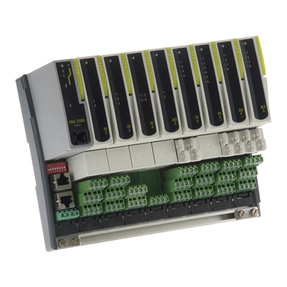
2500 Controller Engineering Handbook 1.4. WHAT IS THE 2500? The 2500 is a modular system which can provide multi-loop PID control, analogue and digital I/O, signal conditioning and computational blocks with a variety of plug-in modules. I/O Control Module (IOC) 2500M Plug-in I/O Modules Always mounted in the left hand position. -
Page 16: The Components Of The 2500
1.6. THE COMPONENTS OF THE 2500 The 2500 is normally supplied as a number of separate parts, identified by a unique model code printed on labels on the packaging and on each item. These codes are explained in Appendix B. -
Page 17: Mechanical Installation
MECHANICAL INSTALLATION The 2500 base unit is intended to be mounted in an enclosure, or in an environment suitable for IP20 rated equipment. It can be DIN or bulkhead mounted. When mounted on DIN rail it is locked with the clamps at each end. -
Page 18: Din Rail Mounting
2500 Controller Engineering Handbook 1.8.1. DIN Rail Mounting For DIN rail mounting, symmetrical, horizontally-mounted 35x7.5 or 35x15 DIN rail to BS EN50022 should be used. Mount the DIN rail, using suitable bolts, ensuring that it makes good electrical contact with the enclosure metal work either via the bolts or by means of a suitable earthing cable. -
Page 19: To Fit A Module
2500 Controller Engineering Handbook 1.8.5. To Fit a Module Note: Polarising keys prevent modules from being fitted to unsuitable terminal units. Pull the module retaining lever forwards into the unlocked position as shown in Figure 1-5. Offer the module up to the terminal unit and the backplane, and push home. -
Page 20: I/O Module Functions
1.9. I/O MODULE FUNCTIONS The 2500 system provides I/O modules designed to accept wiring directly from common control plant transducers , such as thermocouples, transmitters, valve positioners. The I/O modules provide the basic hardware interface. Software features adapt this interface for different ranges or functions, and add signal processing capability. -
Page 21: Chapter 2 The Ioc Module
2. Chapter 2 The IOC Module 2.1. OVERVIEW The Input / Output Controller module (IOC) is the central processing unit of the 2500 system. The IOC maintains a database of all system parameters, updated on a regular tick interval for consistent control loop behaviour. -
Page 22: Operating Modes
2500 Controller Engineering Handbook 2.2. OPERATING MODES The IOC offers several operating modes:- The 'Run' mode provides the normal execution of the I/O and control strategy. The 'Config' mode unlocks system parameters for configuration or re-configuration, while inhibiting the output modules. -
Page 23: Configuration Key
2500 Controller Engineering Handbook 2.2.3. Configuration Key The configuration key ensures that the IOC powers up in configuration mode. The key is fitted into the configuration port of the IOC and has the same effect as powering up the IOC with the config lead connected to a PC, see section 2.2.2. -
Page 24: Configuration Port
EIA232 with a fixed 9600 baud rate, no parity, 8 bit data and 1 stop bit for extremely simple and reliable connection to a PC. Any PC based software supporting Modbus can thus communicate with the 2500 system - including the iTools package. A suitable interconnection cable is available, part 2500A/CABLE/CONFIG/RJ11/(PINDF/3M0. -
Page 25: Status Indication
2500 Controller Engineering Handbook 2.4. STATUS INDICATION Five LED indicators show the status of an IOC module as follows: Colour ALL OFF Green Normal operation Self test failed on power up Yellow Standby (See Note 1) Yellow Configuration &C Normal operation with online IO... -
Page 26: Initialisation And Power On Self Test
‘Flashing' LED On Note 1 LED Off Top LED is ON if the 2500 is in operation level Note 2 Centre LED ON if the 2500 is in standby Lower LED ON if the 2500 is in configuration mode Figure 2-5: LED Indication During Start Up... -
Page 27: Modbus Ioc And Terminal Unit
+24V Figure 2-6: Modbus IOC Module and Terminal Unit The Modbus network connection and the 2500 system power connections are provided by the Terminal Unit; the latter with standard screw terminals, the former with RJ45 sockets. The network connection is used for connection to an operator interface unit, a PC running iTools or 3 party system, or to link further slave 2500 controllers or other Modbus equipment in a system. -
Page 28: The Rj45 Modbus Line Terminator
CAT-5 cable and to match the RJ45 wiring the terminator order code 2500A/TERM/MODBUS/RJ45 should be used. This can be plugged into the free socket in the last 2500 base in the chain; it is presumed that the other end of the cable (usually at the network master) is likewise terminated. -
Page 29: Profibus Ioc And Terminal Unit
2500 Controller Engineering Handbook 2.7. PROFIBUS IOC AND TERMINAL UNIT The Profibus IOC is identified by the front label and the order code printed on the side label. This IOC must be used with a Profibus Terminal Unit. There are two TU options: a standard, a 9-Way D-Type and a dual RJ45 type as shown in Figure 2-9. -
Page 30: Connections To The Network Connectors
2500 Controller Engineering Handbook 2.7.1. Connections to the Network Connectors The 9 pin D-Type connector is intended for installations using standard Profibus cables: Pin No. Signal Name Meaning Shield Shield (ground) Not used RxD/TxD-P Receive/Transmit – Data 'P' Not used... -
Page 31: Profibus 9 Pin Connector Line Termination
2500 Controller Engineering Handbook 2.7.3. Profibus 9 pin Connector Line Termination For 9-pin connectors standard Profibus cables should be used. These cables have special headers on the 9-pin D male connector which allow one or two cables to be connected inot them and have a small termination load built in with an ON’OFF switch, which is set to ON at the two ends of the links. -
Page 32: Devicenet Ioc And Terminal Unit
2500 Controller Engineering Handbook 2.8. DEVICENET IOC AND TERMINAL UNIT The DeviceNet IOC is identified by the front label and the order code printed on the side label. This IOC must be used with the DeviceNet Terminal Unit. LED Status Indicators... -
Page 33: Connections To The Terminal Unit
2.8.2. DeviceNet Terminators The DeviceNet specification states that the bus terminators should not be included as any part of a master or slave. They are not supplied as part of the 2500 DeviceNet termination assembly. 2.8.3. Power The DeviceNet bus is powered form the system, the load being around 100mA. -
Page 34: Ethernet Ioc And Terminal Unit
2500 Controller Engineering Handbook 2.9. ETHERNET IOC AND TERMINAL UNIT The Ethernet IOC is identified by the front label and the order code printed on the side label. This IOC must be used with the Ethernet Terminal Unit. LED Status Indicators... -
Page 35: Connections To The Rj45 Socket
2500 Controller Engineering Handbook 2.9.1. Connections to the RJ45 Socket The RJ45 socket is connected according to the Ethernet standard. RJ45 pin Colour Signal Orange / White Orange Green / White Blue Blue / White Green Brown / White Brown... -
Page 36: Chapter 3 Itools
Alternatively it can be connected to the same network as the pc using a normal cable. 3.2.1. To Connect a Single 2500 Controller to a PC Connection of any 2500 to a PC can be made through the RS232 configuration port located on the front of the IOC module. -
Page 37: To Connect Multiple 2500 Controllers To A Pc
RS485/RS232 communications converter is suitable. All network components (PC, 2500 and KD485) must be set up as appropriate and compatible for a network - each slave with a different address, each working with the same baud rate and parity settings, all components to work 5-wire (duplex) or 3-wire. - Page 38 2500 Controller Engineering Handbook Ethernet IOC If the Ethernet IOC is connected directly to the pc using a cross-over cable, any IP address may be used. Alternatively, the Ethernet IOC must be configured for the network by obtaining a compatible fixed IP address and Subnet mask or by setting up DHCP –...
- Page 39 2500 Controller Engineering Handbook Within the EuroMBus server select Add, Ports then click on the TCP/IP tab: Click Add, or select one of the existing ports and click Edit. Enter a meaningful name in the Name field. Enter the IP address in the Host Name/Address field.
-
Page 40: Starting Itools - Device Detection
STARTING iTOOLS - DEVICE DETECTION As "network master" iTools must identify any and all devices connected to the network - even if just one 2500 is connected through the 'config' port. On request iTools will automatically search for all devices with unique network base addresses. -
Page 41: Standby Mode
In Standby mode the IOC is not controlling but is also not in configuration mode. This mode should not be deliberately set by the user. When the 2500 is in standby mode the iTools icon is displayed with a yellow hand symbol. On the IOC the yellow indicator LED marked “S”... -
Page 42: Instrument Parameters
3.5. INSTRUMENT PARAMETERS In the 2500 system "Parameters" are the numbers and values that represent the state of the machine. Each available parameter has a predefined address in the database. Parameters in iTools are organised into folders which are applicable to a particular subject. For example, to find a loop alarm setpoint go to Control →... -
Page 43: To Change Parameter Values
3. From the pop up window click " " 4. Select the required baud rate, and click OK or Apply The baud rate can only be changed if the 2500 is in Configuration Mode and it is appropriate to the Communication protocol 3.5.5. -
Page 44: Parameter Availability And Alterability
By default only ‘available’ or relevant parameters appear on a page. For example, relative cool gain does not appear in a heat only controller, and integral time does not appear in an On/Off controller. A parameter may be Read Only with the 2500 in operating mode, but Read/Write in Configuration mode. An example is thermocouple linearisation type. -
Page 45: Setting Up An Application
3.7. SETTING UP AN APPLICATION The 2500 can be set up to provide a wide range of application solutions. To this end it offers I/O channel blocks, I/O module blocks, PID loop blocks, timer blocks, counter blocks... and more. To create any control strategy the Applications Engineer can connect these blocks together using software ‘wiring’... - Page 46 2500 Controller Engineering Handbook We need to identify the AI3 channel output (PV) address; navigate as usual to that list: Figure 3-11: AI3 channel list We can see the parameter 'Val' is at address 5207. We could have found this by looking up the published Modbus parameter information.
-
Page 47: Declaring I/O Modules
Figure 3-14: The wiring editor Because there are potentially a very large number of wireable parameters in a 2500 the list is split up into sections and a pull down list “Show Parameters” is used for selection. -
Page 48: Chapter 4 Control
ABOUT THIS SECTION The IOC fitted in the 2500 DIN Rail Controller has a number of options, such as 2, 4 or 8 loops of control and Toolkit Blocks depending upon the option ordered. This section applies to any number of loops. Toolkit blocks are described in Chapter 8. -
Page 49: Loop Overview Parameters
2500 Controller Engineering Handbook 4.2.1. Loop Overview Parameters These parameters are in the Control → LOOP0x list. Name Description Range Status Process Variable. The input process value to be controlled by the loop. The current value of the variable from the wired source, for example an Analogue Input module Process Variable Source. -
Page 50: Loop Configuration
2500 Controller Engineering Handbook 4.3. LOOP CONFIGURATION This is the page used to set up or configure the way in which the loop is designed to operate. In Configuration Mode ALL these parameters are Read/Write, in Operating Mode ALL these parameters are Read ONLY. -
Page 51: Other Loop Configuration Parameters
2500 Controller Engineering Handbook 4.3.2. Other Loop Configuration Parameters Name Description Range Status Cooling Type This applies to the PID output on Channel 2 COOL Lin (0) Linear The control output follows linearly the PID output signal, i.e. 0% PID demand = 0 demand output, 100% PID demand = 100% demand output. -
Page 52: Pid Control
2500 Controller Engineering Handbook 4.4. PID CONTROL PID control, also referred to as ‘Three Term Control’, is a technique used to achieve stable straight line control at the required setpoint. The three terms are: Proportional band Integral time Derivative time The output from the controller is the sum of the contributions from these three terms. -
Page 53: High And Low Cutback
2500 Controller Engineering Handbook 4.4.4. High and Low Cutback While the PID parameters are optimised for steady state control at or near the setpoint, high and low cutback parameters are used to reduce overshoot and undershoot for large step changes in the process. They respectively set the number of degrees above and below setpoint at which the controller will start to increase or cutback the output demand. -
Page 54: Pid Parameters
2500 Controller Engineering Handbook 4.4.6. PID Parameters These parameters are in Control → LOOP0x → L0xPID. The L0xPID List displays all the current working PID parameter values. These are all read only (coloured blue) and are set either following an Autotune (section 4.13) or adjusted manually (section 4.5.1 ‘PID Sets’). The PID terms have been described in previous pages. - Page 55 2500 Controller Engineering Handbook Name Description Range Status Modbus address of the flag used to hold the Integral value I-HSrc -1 means not wired Debump Flag Set to balance integral to maintain the same output demand. Flag Debump resets itself Manual Reset Auto Calc Enable With Integral Time OFF, setting Adc enables calculation of the Manual Reset.
-
Page 56: Gain Scheduling
2500 Controller Engineering Handbook 4.5. GAIN SCHEDULING Gain scheduling is the automatic transfer of control between one set of PID values and another. Gain scheduling may be used in very non-linear systems where the control process exhibits large changes in response time or sensitivity, see Figure 4-8 below. - Page 57 2500 Controller Engineering Handbook The default set up of the loop provides a single set of PID values – all Read/Write. There are 3 sets of PID values available and different strategies to select to change from one PID set to the next. These two parameters may only be changed in configuration level.
-
Page 58: Loop Setpoint
2500 Controller Engineering Handbook 4.6. LOOP SETPOINT This page is used to configure parameters which define the setpoint to a control loop. Figure 4-10: Loop Setpoint The Working Setpoint is the setpoint used by the control loop and may be derived from a number of different sources. -
Page 59: Rate Limit And Holdback Parameters
2500 Controller Engineering Handbook 4.6.2. Rate Limit and Holdback Parameters These parameters are also in the Control → LOOP0x → L0x_SP list. Holdback is used to stop the setpoint ramp when the Process Variable is unable to keep up with the changing setpoint. -
Page 60: Remote Setpoint Parameters
Remote Setpoint Enable Source. The source from which the remote setpoint enable is L-rSrc wired 4.6.4. Control Setpoint – Ramp Parameters These parameters are also in the Control → LOOP0x → L0x_SP list. They are used to synchronise ramp segments over a number of 2500 controllers, using communications. Name Description Range Status Next Slave Instrument Target Setpoint. -
Page 61: Loop Setpoint Configuration
2500 Controller Engineering Handbook 4.7. LOOP SETPOINT CONFIGURATION These parameters set up or configure the way in which the loop setpoints are designed to operate. Figure 4-11: Loop Setpoint Configuration 4.7.1. Setpoint Function Block The schematic diagram below shows how the setpoints are connected and selected and where the setpoint limits are applied. -
Page 62: Setpoint Configuration Parameters
2500 Controller Engineering Handbook 4.7.2. Setpoint Configuration Parameters These parameters are in the Control → LOOP0x → L0xSPC list. Name Description Range Status Remote Tracking. Defines the local setpoint behaviour when changing from Remote rmTr to Local setpoint. Read only in Operator Mode. -
Page 63: Control Output
2500 Controller Engineering Handbook 4.8. CONTROL OUTPUT 4.8.1. Output Function Block This block diagram shows how the parameters and limits are used on the Output of a PID block. PID Block Output Track IP Track OP High Limit OP Rate Limit... - Page 64 2500 Controller Engineering Handbook Name Description Range Status Output Rate Limit. Sets the rate of change in output demand in seconds OPrr Output Rate Limit Source. Modbus address of the parameter used as the Output Rate OPrSrc Limit. –1 means not wired.
-
Page 65: Valve Control Outputs
2500 Controller Engineering Handbook 4.8.3. Valve Control Outputs There are two types available Bounded or Boundless Mode. Bounded requires feedback from a potentiometer giving valve position. Boundless (sometimes known as Velocity or Unbounded mode) does not require position feedback. Figure 4-16: Valve output Parameters 4.8.4. -
Page 66: Ratio Control
4.9.1. Basic Ratio Control Each loop in the 2500 contains a ratio control function block. Figure 4-17shows a block diagram of a simple ratio controller. The lead PV is multiplied or divided by the ratio setpoint to calculate the desired control setpoint. - Page 67 2500 Controller Engineering Handbook Ratio parameters are found in Control → LOOP0x → L0xRAT Name Description Range Status SP Setpoint generated by the ratio calculation in engineering units Measured Ratio Continuous calculation of the actual measured ratio. It is calculated MRatio from the Lead PV and the Process PV.
-
Page 68: Cascade
4.10.2. Trim Mode The 2500 controller uses trim mode cascade control an example of which is shown in Figure 4-19. The slave controls the temperature in a furnace. The master is measuring the temperature of the workpiece and controlling the setpoint of the slave. -
Page 69: Cascade Parameters
2500 Controller Engineering Handbook 4.10.5. Cascade Parameters Cascade control is selected by the LoopType = Cascade . Figure 4-21: Cascade Control Parameter List Cascade parameters are found in Control → LOOP0x → L0xCAS. Name Description Range Status Cascade Mode. Selected Cascade Mode... - Page 70 2500 Controller Engineering Handbook Name Description Range Status The following parameters may be hidden if not required for the operation of the instrument. To reveal uncheck the ‘Hide Parameters’ box in ‘Options → Parameter Availability Settings’ High Range of Slave Loop. Maximum value of the PV of the auxiliary loop SlvHR Low Range of Slave Loop.
-
Page 71: Override
2500 Controller Engineering Handbook 4.11. OVERRIDE Overview Override Control allows a secondary control loop to override the main control output in order to prevent an undesirable operating condition. The override function can be configured to operate either in minimum, maximum or select mode. -
Page 72: Override Parameters
2500 Controller Engineering Handbook 4.11.1. Override Parameters Override is configured by setting L0xCFG → Loop Type to Override. Figure 4-23: Override Control Parameter List Override parameters are found in Control → LOOP0x → L0xOVR. Name Description Range Status Override Type. Override Type... -
Page 73: Tuning
4.13.1. Autotune Parameters In the 2500 Loops do not have their own individual Autotune. There is a single tuning block available to be used on the loops one at a time. There is no configuration required. - Page 74 2500 Controller Engineering Handbook Name Description Range Status Auto tune high power limit. Set this to limit the maximum output demand level which TnOH the controller will supply during the tuning process. If the high output power limit set in the output list is lower the autotune high limit will be clipped to this value Tuning State.
-
Page 75: Cascade Tuning
2500 Controller Engineering Handbook 4.13.2. Cascade Tuning When tuning a cascade loop it is necessary that both master and slave loops are tuned. It is recommended that each loop is tuned independently using the procedure below. Because the slave loop is used by the master loop it must be tuned first. - Page 76 2500 Controller Engineering Handbook Step 8: Return to control The slave and master loops should now be tuned. Try changing the main setpoint and observe the response. If the master PV response is oscillatory then you may not have restricted the disturbance of the slave enough.
-
Page 77: Loop Diagnostics
Low, Deviation High, Deviation Low, and Deviation band. One of four alarms, Alarm 4, may also be set as a ‘rate of change’ alarm. The alarm function blocks have many features. All the alarms in the 2500 use the same function block and are described in detail in Chapter 5. -
Page 78: Chapter 5 Alarms
2500, alarms and events can be considered the same. 5.2. TYPES OF ANALOGUE ALARM USED IN THE 2500 This section describes graphically the operation of different types of alarm used in the 2500 controller. For analogue alarms the graphs show measured value plotted against time. 5.2.1. Absolute High... -
Page 79: Deviation High Alarm
2500 Controller Engineering Handbook 5.2.3. Deviation High Alarm This alarm (devHi) occurs when the difference between the process variable and the setpoint is positive by greater than the alarm setpoint. Alarm ON Alarm OFF Alarm Hysteresis Working Setpoint ... -
Page 80: Rate Of Change Alarm
2500 Controller Engineering Handbook 5.2.6. Rate Of Change Alarm The Process Value falls faster than the alarm setting or rises faster than the alarm setting. Alarm On ↑ Alarm Off Negative Rate of Change set to x units per min Actual rate of change >... -
Page 81: Types Of Digital Alarm Used In The 2500
2500 Controller Engineering Handbook 5.3. TYPES OF DIGITAL ALARM USED IN THE 2500 This table describes the operation of different types of digital alarm used in the 2500 controller. ITools List Description IstruE Alarm output set when input is TRUE... -
Page 82: Deviation Band With Blocking
2500 Controller Engineering Handbook 5.4.3. Deviation Band With Blocking The alarm only occurs after the start up phase when low deviation alarm has first entered a safe state. The next time an alarm occurs, whether high band or low band will cause the alarm to become active. -
Page 83: Latched Alarm (Absolute High) With Manual Reset
GROUPS & ALARM STATUS WORD All the alarms in the 2500 are in groups associated with a PID loop, an I/O channel, or are User defined alarms. All the alarm active flags and alarm acknowledged flags are also available within a 16 bit Alarm Status Word ‘AlmSW’, in the following standard format. -
Page 84: Alarm Parameters
2500 Controller Engineering Handbook 5.7.1. Alarm Parameters These are found in Control → LOOP0x → L0xALM Name Description Range Status Group Acknowledge. To acknowledge all alarms associated with this loop. The action GrpAck which follows depends on the type of latching configured, see section 5.5. -
Page 85: User Alarms
2500 Controller Engineering Handbook 5.8. USER ALARMS The 2500 has four unassigned analogue alarms and four unassigned digital alarms. Figure 5-13: Analogue User Alarm (Configuration Level) 5.8.1. User Alarm Parameters – Analogue These are found in User_Alarms → AN_ALM Name... -
Page 86: I/O Alarms
2500 Controller Engineering Handbook 5.9. I/O ALARMS Each I/O module has 8 alarms (designated A to H) which are shared between the channels of the module. This sharing has a default setting but, in configuration mode, individual alarms may be reassigned to other channels. -
Page 87: Instrument Status Alarms
2500 Controller Engineering Handbook 5.10. INSTRUMENT STATUS ALARMS These are self diagnostic alarms provided to simplify fault finding. Bit masks are provided to allow only selected events to be reported in the appropriate alarm output. Alarms are reported at the channel level, at the module level and at a system (IOC) level. -
Page 88: Status Of All Channels In A System (Ioc)
When IOStat has a value Reserved / Analogue input saturated 4 (or zero) the red LED on Any channel Module fault the 2500 IOC will be off. Any Module is missing Any Wrong Module fitted 1024 Any Unrecognised Module fitted... -
Page 89: Chapter 6 Operator
2500 Controller Engineering Handbook 6. Chapter 6 Operator This folder contains a number of system wide and diagnostic parameters. 6.1. LINEARISATION TABLES These parameters are found in Operator → Lin Tables and are provided to allow the customised linearisation to be checked. -
Page 90: Digital Communications Parameters
2500 Controller Engineering Handbook 6.2.1. Digital Communications Parameters These parameters are found in Operator → COMMS. See also Chapters 9,10, 11 and 12 for further details. Name Description Range Status Addr Comms Address. Unit address Modbus:- normally taken from the IOC terminal unit digit switch (see section 2.6.3). - Page 91 2500 Controller Engineering Handbook The following parameters are only relevant to the Ethernet IOC: IPaddr1 IP Address 1: in the standard Ethernet format, aaa.bbb.ccc.ddd, this is the aaa field IP Address 2: in the standard Ethernet format, aaa.bbb.ccc.ddd, this is the...
- Page 92 2500 Controller Engineering Handbook Note 1:- The table shows the baud rates supported in different versions:- Modbus Baud Rate Software Version V1 2400 (3) 4800 (2) 9600 (0) 19,200 (1) 38,400 (5) Profibus Baud Rate Software Version V1 Set by the...
-
Page 93: System
Input values still work but there are no calculations Stndby(1) Configuration: the controller is being set up and is not functioning Config (2) Instrument Identity. A unique hex number for the 2500 product, displayed as decimal as follows:- Code 2500E 2500C... - Page 94 2500 Controller Engineering Handbook Name Description Range Status IONrec IO Network Recovery Time I/O Network Watchdog Timeout. Defines the instrument behaviour when the NwdAct network watchdog is activated. EntSby (0) Enter Standby. Go into Standby Mode on failure and stay there...
- Page 95 AlmSW Instrument Alarm Status Word. Returns the bitwise AND of ‘InstSt’ and the bit mask ‘Mask’. The following parameters are used by external masters to control the ramp blocks in the 2500: Global SRL Hold Flag. Holds all ramps GHdSrc Global SRL Hold Flag Source.
- Page 96 2500 Controller Engineering Handbook Name Description Range Status ApName Application Name This is an 8 character field for the manual entry of a configuration name. E.g. the name of the clone file currently loaded. ApVers Application Version. A 5 digit field for the manual entry of the application version.
-
Page 97: Password Entry
Reference Cal password 6.6. DIAGNOSTICS These parameters are used to assess the cycle time that the 2500 unit can achieve. It is particularly useful for 2500 units with the 8 PID loops. 6.6.1. Diagnostic Parameters These parameters are found in Operator → DIAG... -
Page 98: System Descriptions
2500 Controller Engineering Handbook 6.7. SYSTEM DESCRIPTIONS These parameters provide descriptions of system parameters. They are found in Operator → DESCR Name Description Range Status Company ID Product ID Instrument Version Number Instrument Serial Number SerialNo Feature Pass Code 1. Used to set which features are available: number of loops, user PCode1 calculations. -
Page 99: Chapter 7 I/O Modules
7.1. OVERVIEW In the 2500 system, I/O Modules perform equipment interface functions to measure or generate raw voltage, resistance or current. Most transducer types can be connected straight into the I/O module via screw terminals. Each I/O Module is dedicated to a particular function - analogue or digital, input or output. Channels on a module may be set for different functions;... -
Page 100: I/O Module Indicator Leds
2500 Controller Engineering Handbook 7.3. I/O MODULE INDICATOR LEDS All modules support status indicator LED's to reflect I/O terminal status. All I/O modules offer a green indicator. This is illuminated when the module is fitted and powered and when the IOC matches the 'ReqID' parameter for that base slot with the actual module type 'ActID'. -
Page 101: Channel Isolation
7.4. CHANNEL ISOLATION The 2500 is easy to use because transducers can be directly wired into any appropriate channel at the terminals. Such direct connection introduces safety implications, particularly risk of shock hazard. Electrical isolation minimizes such risks even when equipment goes faulty, and particularly when some transducers have to be run "live". -
Page 102: Channel Status And Errors
7.5. CHANNEL STATUS AND ERRORS Any control strategy and configuration of the 2500 must consider wiring and plant faults, errors and exceptions. Even simple faults may affect the safe running of the system. The 2500 offers several levels of alarms and status indicators to help handle problems. -
Page 103: Io Module Configuration Concepts
The IOC will interrogate any fitted module and report the type in 'ActID'. For the module to work these parameters must match, as shown in Figure 7-8 above. Note that 'ReqID' will not change unless the 2500 is in "config" mode. Part No HA027115 Issue 4.0 Mar -11... - Page 104 2500 Controller Engineering Handbook Module Status Parameters Name Description Range Status ModSta Module Status. A bit field reporting the module status: ModSta is 0 if module is OK and working. Value (decimal) Set when Missing Module Wrong Module Unrecognised Module...
- Page 105 2500 Controller Engineering Handbook Value (decimal) Set when Channel 1 alarm active Channel 1 alarm acknowledged Channel 2 alarm active Channel 2 alarm acknowledged Channel 3 alarm active Channel 3 alarm acknowledged Channel 4 alarm active Channel 4 alarm acknowledged...
-
Page 106: Module Channel Parameters
2500 Controller Engineering Handbook 7.6.2. Module Channel Parameters When the module is identified correctly the I/O channels can be set up. These parameters are found in IO → Module0x → M0x_Cy Figure 7-9: Channel Parameter List Example Figure 7-9 shows an example of a channel parameter list - in this case, for a DO4 module. -
Page 107: Analogue Input Modules
2500 Controller Engineering Handbook 7.7. ANALOGUE INPUT MODULES There are three different analogue input modules - the AI2, the AI3 and the AI4. These are supported by a number of terminal units, each optimised for different input sensors. All these modules and channels function the same way and with similar channel parameters, differing only in electrical interface options and characteristics. - Page 108 2500 Controller Engineering Handbook 3-Wire PRT Input 8.2kΩ I1 or 20MΩ Sensor None Break Action Down A1 or High impedance input amplifier C1 or Internal view Figure 7-12: 3-Wire PRT Input 4-Wire PRT Input 8.2kΩ I1 or B1 or High impedance...
-
Page 109: Ai2 Terminal Connections
2500 Controller Engineering Handbook Milli-Volt Input 270KΩ 20MΩ H1 or Sensor Break Action None m-Volt Source Down A1 or High impedance input amplifier C1 or Internal View Figure 7-15: mV Input Volts Input 270KΩ Voltage Source H1 or High impedance 33KΩ... -
Page 110: Ai3 Isolation Barriers
2500 Controller Engineering Handbook 7.7.4. AI3 Isolation Barriers 2500 I/OBus and IOC Figure 7-18: AI3 Isolation Barriers 7.7.5. AI3 mA Input Equivalent Circuit P1, P2 or P3 Current 200Ω Source C1, C2 or C3 High impedance Cut- 60Ω input amplifier... -
Page 111: Ai4 Isolation Barriers
2500 Controller Engineering Handbook 7.7.8. AI4 Isolation Barriers ADC1 ADC2 2500 I/OBus ADC3 ADC4 Figure 7-20: AI4 Isolation Barriers 7.7.9. AI4 Analogue Input Equivalent Circuits The equivalent circuits below show details of analogue inputs, in particular sensor break circuits. Thermocouple Input 20MΩ... -
Page 112: Ai4 Terminal Connections
2500 Controller Engineering Handbook 7.7.10. AI4 Terminal Connections The AI4 Terminal Unit provides 8 screw terminals for channel wiring: 7.7.11. Analogue Input Parameters Channel Type and Enumerations Name Description Channel Type TYPE PT100 resistance thermometer – 3 wire RTD3 (0) - Page 113 2500 Controller Engineering Handbook Name Description Range Status Custom curve Name 3 Cust 3 (22) The actual value of the channel in engineering units The next four parameters are used to calibrate process type (V/mV/mA inputs). They are not used for thermocouple, RTD or pyrometer inputs.
- Page 114 2500 Controller Engineering Handbook Name Description Range Status UCAL User Calibration Enable. Allows single offset calibration correction using the ‘Offset’ parameter for single point calibration offset or ‘PointL’ with ‘OfsetL’ and ‘PointH’ with ‘OfsetH’ for 2 point correction See also section 7.11.3.
- Page 115 2500 Controller Engineering Handbook Name Description Range Status Yes. Blocking is active YES (1) Status Alarm Latching. See also section 5.5. Ltch No blocking no (0) Yes. Blocking is active YES (1) Status Alarm Acknowledge. See also section 5.5. no (0)
-
Page 116: Analogue Output Module
2500 Controller Engineering Handbook 7.8. ANALOGUE OUTPUT MODULE There is one Analogue Output Module (AO2) which provides two channels offering either voltage or current output drive. Each channel is independently software settable. Both channels work the same way, calculating the output drive value 'MeasV' from the block parameters and the demanded 'Val' value. -
Page 117: Analogue Output Channel Parameters
2500 Controller Engineering Handbook 7.8.4. Analogue Output Channel Parameters These parameters are found in IO → Module0x → MOD0x AO2 Channel Type and Enumeration Name Description Range Status TYPE Channel Type Volt output V (O) (30) Milliamp output mA (O) (31) AO2 Channel I/O Parameters These parameters are found in IO →... - Page 118 2500 Controller Engineering Handbook AO2 Status and Alarm Parameters These parameters are found in IO → Module0x → M0x_Cy Name Description Range Status Status - a bit mapped field, non-zero on error. ChStat Value (dec) Set when Sensor break detected...
-
Page 119: Digital Input Modules
2500 Controller Engineering Handbook 7.9. DIGITAL INPUT MODULES There are five different digital "input" modules - the DI4, the DI6\115V, the DI6\230V, the DI8\Logic, and the DI8\Contact. These all behave in exactly the same way, with the same channel parameters, but with differences in the type and specification of the channel circuits. -
Page 120: Di6 115V And 230V
2500 Controller Engineering Handbook 7.9.5. DI6 115V and 230V The DI6 modules offer 6 logic input channels designed for direct ac supply. 7.9.6. DI6 Isolation Barriers 2500 I/OBus Figure 7-29: DI6 Channel Isolation Barriers DI6 Equivalent Circuits L1 to L6 68nF 1K5Ω... -
Page 121: Di8 Logic
2500 Controller Engineering Handbook 7.9.7. DI8 Logic The DI8 offers 8 logic input channels. Unlike the DI4, the contact and logic input versions are order options, again fixing the channel function for the whole module. 7.9.8. DI8 Logic Input Isolation Barriers... -
Page 122: Di8 Contact Input
2500 Controller Engineering Handbook 7.9.11. DI8 Contact Input This version of the DI8 supports switch contact inputs. The channel configuration is exactly the same as for the logic input version; and the same terminal unit is used. 7.9.12. Digital Input Parameters Channel Type and Enumerations These parameters are found in IO →... - Page 123 2500 Controller Engineering Handbook Digital Input IO Parameters These parameters are found in IO → Module0x → Mox_Cy Name Description Range Status The actual value of the channel in engineering units on (0) OFF (1) Invert. Change the polarity of the input signal...
-
Page 124: Digital Output Modules
2500 Controller Engineering Handbook 7.10. DIGITAL OUTPUT MODULES There are just three different digital "output" modules - the DO4\EP, the DO4\24, and the RLY4 module. All blocks work the same way, with the electrical output 'MeasV' being processed from the demanded 'Val' value. -
Page 125: Relay Module Rly4
2500 Controller Engineering Handbook 7.10.6. Relay Module RLY4 The RLY4 module "output" contains four power relay contacts capable of working at 2A, 250Vac. Otherwise, module operation is exactly the same as the other logic output modules. Channel Types: On/Off, TPO, Valve Raise/Lower... -
Page 126: Digital Output Channel Parameters
2500 Controller Engineering Handbook 7.10.10. Digital Output Channel Parameters DO Channel Type and Enumerations These parameters are found in IO → Module0x → M0x_Cy Name Description Range Status Channel Type TYPE OnOff (O) (40) On/Off output TimePr(41) TPO - Time proportioning output... - Page 127 2500 Controller Engineering Handbook DO Status and Alarm Parameters Name Description Range Status Status Alarm Bit Mask – Used to select which of the channel status bits 'ChStat' should Mask be used to set the channel alarm status IO → Module’nn’ → MOD’nn’ → ChAISW...
-
Page 128: Configuration Examples
2500 Controller Engineering Handbook 7.11. CONFIGURATION EXAMPLES The following are examples use key configuration parameters to configure different I/O modules. 7.11.1. Thermocouple or RTD Input Fit an Analogue Input module into a suitable position on the base, for example AI2 in slot 03. -
Page 129: Analogue Input: Mv, Ma, V, Ohms
2500 Controller Engineering Handbook 7.11.3. Analogue Input: mV, mA, V, ohms Using the previous example: In IO → Module03 → M03_C1 set ‘TYPE’ = ‘mv’. set ‘LinTyp’ to match the curve of the transducer in use. It is now necessary to scale the input to match the displayed reading with the electrical output levels from the transducer. -
Page 130: Analogue Output
2500 Controller Engineering Handbook 7.11.4. Analogue Output Fit an Analogue Output module into a suitable position on the base, for example AO2 in slot 04. In IO → Module04 → MOD04 set ‘ReqID to ‘Analogue Output’ (AO2) In IO → Module04 → M04_C1 (or 2) set ‘Channel Type’... -
Page 131: Digital Input
2500 Controller Engineering Handbook 7.11.5. Digital Input Fit a Digital Input module into a suitable position on the base, for example DI8 in slot 01. In Module01 → MOD01 set ‘ReqID to ‘Digital Input’ (DI8) In IO → Module01 →... -
Page 132: Digital Outputs
2500 Controller Engineering Handbook 7.11.6. Digital Outputs Fit a Digital Output module into a suitable position on the base, for example DO4 (or RLY4) in slot 02. In Module02 → MOD02 set ‘ReqID to ‘Digital Output’ DO4 (or RLY4) In IO → Module01 →... -
Page 133: Valve Position Controller
2500 Controller Engineering Handbook 7.11.7. Valve Position Controller This example assumes:- IO Module 01 is configured for PV input IO Module 02 is configured for potentiometer input IO Module 03 is configured for relay output Loop 01 is configured for bounded valve position control... -
Page 134: To Calibrate A Potentiometer Input
2500 Controller Engineering Handbook 7.11.8. To Calibrate a Potentiometer Input When using the controller in bounded valve position control mode, it is necessary to calibrate the feedback potentiometer to correctly read the position of the valve. This is carried out using iTools. -
Page 135: Chapter 8 Toolkit Blocks
‘USRVAL’ may be used as digital flags or analogue parameters. In the case of digital flags zero is interpreted as OFF, any other value is ON. Toolkit Blocks are only available if the 2500 IOC is ordered with the Toolkit Blocks feature enabled. -
Page 136: Analogue Operators
2500 Controller Engineering Handbook 8.2.1. Analogue Operators Up to 32 calculations are available. Operators may only be changed in configuration mode. Operator Description None The selected analogue operator is turned off The output result is the addition of Input 1 and Input 2 The output result is the difference Input 1 and Input 2 where Input 1 >... -
Page 137: Analogue Block Parameters
2500 Controller Engineering Handbook 8.2.2. Analogue Block Parameters These parameters are found in Toolkit Blocks → Analog → AOPR01 to 32 Figure 8-3: Analogue Blocks - Parameter List The schematic view shown above is displayed in the usual parameter list format. However by invoking the Toolkit Block editor (View →... - Page 138 2500 Controller Engineering Handbook Name Description Range Status Operator. To define the analogue operator type Oper Use the Toolkit block editor for graphical explanation For types of operator see section 0. Input 1 Value. The parameter value used for Input 1 P1_Val Input 1 Source.
-
Page 139: Digital Blocks
2500 Controller Engineering Handbook 8.3. DIGITAL BLOCKS Digital Blocks allow the controller to perform combinational logic on two input values. These values can be sourced from any available parameter including Analogue Values, User Values and Digital Values. The parameters to use, the type of calculation to be performed, input value inversion and ‘fallback’ value are determined in Configuration. - Page 140 2500 Controller Engineering Handbook However by invoking the Toolkit Block editor (View → Toolkit Blocks on the Menu bar) the same information is available in a more graphical format as shown in the following view. Figure 8-7: Digital Blocks – Editor The above views show the result of the configuration example in section 8.3.3.
-
Page 141: Example - To Produce A Logic Calculation Block
2500 Controller Engineering Handbook 8.3.3. Example – To Produce a Logic Calculation Block This example is included to illustrate the principle of configuring Digital Blocks using the Parameter List. The example is a ‘comparator’ which compares the value of two inputs using the < (Less Than <) operator. The first input (input 1) in this example is taken from the output of an analogue input module. -
Page 142: User Values
2500 Controller Engineering Handbook 8.4. USER VALUES A User Value is a variable which can be defined by the user and is available for derived calculations. They are found in Toolkit Blocks → USRVAL. They may be used as analogue values or digital where any non zero value is considered ‘True’... -
Page 143: Timer Blocks
Timer Blocks allow the controller to use time information as part of the control process. They can be triggered by an event and used to initiate an action. For example, an action may be delayed following a particular event. The Timer Blocks fitted in the 2500 controller are: Timers Up to eight Timer Blocks each having four modes of operation are explained in section 8.6. -
Page 144: Off Delay Timer Mode (Delay)
2500 Controller Engineering Handbook 8.6.2. Off Delay Timer Mode (DELAY) This timer provides a delay between the trigger event and the Timer output. If a short pulse triggers the Timer, then a pulse of one sample time (110ms) will be generated after the delay time. -
Page 145: One Shot Timer Mode (1 Shot)
2500 Controller Engineering Handbook 8.6.3. One Shot Timer Mode (1 SHOT) This timer behaves like a simple oven timer. • When the Time is edited to a non-zero value the Output is set to On • The Time value is decremented until it reaches zero. The Output is then cleared to Off •... -
Page 146: Minimum On Timer Mode (Cmprss)
2500 Controller Engineering Handbook 8.6.4. Minimum On Timer Mode (CMPRSS) This timer has been targeted at guaranteeing that the output remains On for a duration after the input signal has been removed. It may be used, for example, to ensure that a compressor is not cycled excessively. -
Page 147: Timer Parameters
2500 Controller Engineering Handbook 8.6.5. Timer Parameters These are found in Toolkit Blocks → Timers → TMR1 to 8. Figure 8-13: Timers Parameter List Name Description Range Status Type Timer Type. This selects the type of timer from those described in the previous... -
Page 148: Counters
2500 Controller Engineering Handbook 8.7. COUNTERS Up to eight Counter blocks are supported per IOC. The counter provides a function to count transitions from 'OFF' to 'ON' The counter can be set to two modes count 'UP' or 'DOWN', it has external wireable enable 'En', a reset 'Rst' and a clear overflow flag 'COv' In 'UP' mode, when 'En' is set to one (Yes) the block increments the 'COUNT' from zero to the target 'Tgt'. - Page 149 2500 Controller Engineering Handbook Name Description Range Status Direction. Defines the direction of count in response to clock pulses The Count is limited to a maximum count of 2,147,483,647. Up (0) Count up In 'UP' mode, when 'En' is TRUE (Yes) the block increments the 'COUNT' from zero to the target 'Tgt'.
-
Page 150: Totalisers
Totalisers are used to measure the total quantity of a measurement integrated over time (e.g. flow, power). There is a total of eight totaliser blocks in the 2500 controller. Outputs from the totaliser blocks are integrated values of the inputs. An alarm state and a pulse output is provided and can be wired to a counter block or external electromechanical counter to extend the upper range of totalisation. - Page 151 2500 Controller Engineering Handbook Name Description Range Status Totaliser Monitored Parameter Value. Current input value. 99999 -19999 Totaliser Monitored Parameter Source. Modbus address of the source from which the IPSrc Monitored Parameter is derived. -1 indicates NOT wired Totaliser Reset. In Reset the totaliser will be zeroed, and alarms will be reset.
-
Page 152: Wiring
2500 Controller Engineering Handbook 8.9. WIRING Soft Wiring (sometimes known as User Wiring) refers to the connections which are made in software between function blocks. This section describes the principles of soft wiring. In general every function block has at least one input and one output. Input parameters are used to specify where a function block reads its incoming data (the ‘Input Source’). -
Page 153: Point To Point Wiring
8.10. POINT TO POINT WIRING The user wiring system in earlier versions (up to V3.07) of the 2500 requires that all variables be ‘wired to’. This requires that each variable that may be ‘wired to’ is allocated an additional Modbus address that contains the ‘variable source’... -
Page 154: Relative Humidity
(RH in %) and the Dew Point temperature and allows for compensation of atmospheric pressure and psychrometric constant. As with any other transducer input, a 2500 analogue input may also be connected to a solid state sensor giving RH directly. -
Page 155: Zirconia - Carbon Potential Control
2500 Controller Engineering Handbook 8.12. ZIRCONIA - CARBON POTENTIAL CONTROL 8.12.1. Overview An available option within the 2500 is the Zirconia function block. This feature is used to measure carbon potential, furnace dew point or oxygen concentration. 8.12.2. Zirconia Probe Parameters The key Zirconia configuration parameter is the actual equation used, ‘ZrFn’. - Page 156 2500 Controller Engineering Handbook Name Description Range Status Gas Reference. Required value which defines the % carbon monoxide in the gas used for H-CO carburising. See also section 8.12.4 Remote Gas Reference. Remote required value which defines the % carbon monoxide in RmH-Co the gas used for carburising.
-
Page 157: Temperature Control
A gas analyser may be used to determine the %CO concentration. If an analogue output is available from the analyser, it can be fed into the 2500 Zirconia block to adjust the calculated % carbon reading automatically. The analyser signal should be wired to the Remote Gas Ref/Process Factor ‘RmH-CO’ and the Remote Gas Enable ‘RmGEn’... -
Page 158: Automatic Probe Cleaning
Automatic Probe Cleaning The 2500 zirconia block has a probe clean and recovery strategy. A short blast of compressed air is used to remove any soot and other particles that may have accumulated on the probe. The air blast continues for the time set in Probe Cleaning time ‘bot’. -
Page 159: Chapter 9 Modbus Communications
Lists shown in this handbook contain the address column. Because there are many addresses within a 2500 and there is potentially a large variety of IOC type, Base size, I/O module type, channel setup etc. using iTools is the best way to determine the addresses of the parameters that are required in a particular system. -
Page 160: Communications Blocks
2500 Controller Engineering Handbook 9.3. COMMUNICATIONS BLOCKS 9.3.1. Block Communications Modbus communications is made much more efficient by reading parameters in blocks rather than one by one. Actual data rates depend on many factors, but typically at 9600 bits/sec, read one by one, a data rate of about 30 parameters per second may be achieved. -
Page 161: Chapter 10 Profibus Communications
Master. The cable must be terminated at both the Master end and at the last slave; if this is a 2500 fit the two links on the terminal unit in the high position. -
Page 162: To Create A New Gsd File
2500 Controller Engineering Handbook 10.5. TO CREATE A NEW GSD FILE Profibus Parameters are defined as Input parameters or as Output parameters. Input parameters are read every Profibus cycle, output parameters are written to every cycle. This means, for example, that if the Profibus Master is writing to setpoint ‘SP1’... -
Page 163: To Save The Gsd File
2500 Controller Engineering Handbook Continue adding to the Input and Output lists until all the required parameters have been added to the appropriate list. Parameters may be repositioned within a list by using the mouse to drag and drop a parameter within its list. -
Page 164: Operating And Application Notes
The required GSD file is then imported. A single GSD file may be used for a number of actual 2500 systems on the Profibus network if the same parameter set is of interest on each. If not a separate file must be produced for each different 2500. -
Page 165: Chapter 11 Devicenet Communications
11. Chapter 11 Devicenet Communications 11.1. OVERVIEW The 2500 supports DeviceNet as a “Generic device type, Group 2 only server” with the following specifications: • Support I/O messaging of up to 60 analog variables of Input data, and 60 analog variables of Output data. -
Page 166: Custom Parameter Mapping
2500 Controller Engineering Handbook 11.4. CUSTOM PARAMETER MAPPING The DeviceNet interface uses the 2500s standard Modbus indirection table to parameterise its application specific Send and Receive tables. Custom mapping is done with iTools and is stored with the applications clone file. -
Page 167: Chapter 12 Ethernet Communications
12.1.1. Support for other Ethernet utilities In addition to the MODBUS TCP protocol, the 2500 IOC supports the standard Ethernet ‘ping’ utility to assist in fault finding. Other interfaces such as http, ftp or telnet are not currently supported. NOTE 1:- When the configuration port is in use, the Ethernet network port is disabled for general Modbus/TCP traffic. -
Page 168: Configuration Of The 2500 For Ethernet
12.2.1. General The 2500 IOC Ethernet capability is provided by an interface board installed within the IOC case. This interface board communicates to the IOC internally using a standard Modbus interface at 38400 baud. The Ethernet port is a 10baseT port and can be connected to a hub or switch with Cat5 cable via the standard RJ45 connector. -
Page 169: Ethernet Communications Parameters
2500 Controller Engineering Handbook 12.3. ETHERNET COMMUNICATIONS PARAMETERS The 2500 Ethernet IOC address parameters may be found in the Operator.COMMS list. Figure 12-1: Communications Parameters 12.3.1. Unit Ident Enable This parameter controls how the instrument responds to the value in the Modbus TCP Unit Ident field. The following value options are available:- 0 = ‘Strict’... -
Page 170: Subnet Mask
There are situations where a particular master needs guaranteed access to the 2500 IOC at all times. The ‘preferred master’ IP address can be used to ensure this availability. When this parameter(s) is configured with the appropriate master’s IP address, only three sockets will be generally available, the fourth is reserved for a... -
Page 171: Mac Address
‘-‘ is the standard MAC address separator. The MAC address must be stored in the device that connects to the Internet - for the 2500 Ethernet IOC; this is the interface board. The MAC address value seen through iTools has to be read from the interface board. If the configuration cable is plugged in at power up, communications to the interface board is inhibited and the MAC address parameters seen by iTools will all be 0. -
Page 172: Modbus Exceptions
The yellow LED indicates receive activity. It will flash for ALL network activity on the local link – not just traffic addressed to the 2500 Ethernet IOC. • The green LED indicates transmit activity. This will only flash when the 2500 Ethernet IOC is replying to received requests addressed to the instrument. Those parameters are in Operator → COMMS list... -
Page 173: Chapter 13 Calibration
To support such corrections on analogue I/O channels the 2500 offers several levels of "user calibration": • Simple Cal Offset correction (input channels);... -
Page 174: To Perform Offset Calibration
The correction is enabled by setting the 'UCAL' parameter to 'USEr (1), normal operation is restored by changing UCAL to 'FAct (0)'. All these parameter should be visible and alterable only when the password 'UserPW' is set and the 2500 put into 'Config' mode. ☺... -
Page 175: To Perform User Calibration
2500 Controller Engineering Handbook 13.3.1. To Perform User Calibration Select ‘UserPW’ in Operator → PASSWD. Enter the password (factory default 12). Navigate to the appropriate channel list Double-click the ‘PointL’ parameter and enter the value at which the low offset is to be applied Double click the ‘OfsetL’... -
Page 176: Reference Calibration
2500 Controller Engineering Handbook 13.4. REFERENCE CALIBRATION Reference calibration is particularly useful for eliminating residual system errors. It is another 2-point (straight line) method, but rather than altering the PV it directly changes the electrical signal conversion at the terminals. -
Page 177: Analogue Input Calibration Procedure
The 'Calibration State' parameter is then changed to start the calibration process; the 2500 samples the connected signal many times. Internal calculations are executed to normalise the measured data to match exactly the predefined expected value. This compensates for internal errors - for example, offset, gain, and lead resistance. -
Page 178: Analogue Output Calibration Procedure
2.000mA 18.000mA Table 13-2: Analogue Output Calibration Points The password 'RefPW' must be set and the 2500 in 'Config' mode, with iTools Parameter Value Selections unrestricted to show all parameter options. ☺ Calibration tip: a calibration step value of 100 should affect the V output by about 35mV, and current output by about 75uA. -
Page 179: Appendix A Specification
2500 Controller Engineering Handbook 14. Appendix A SPECIFICATION A1 INSTALLATION CATEGORY AND POLLUTION DEGREE This product has been designed to conform to BS EN61010 installation category II and pollution degree 2. These are defined as follows: INSTALLATION CATEGORY II The rated impulse voltage for equipment on nominal 230V ac mains is 2500V. - Page 180 2500 Controller Engineering Handbook Ethernet Communications Connectors: One RJ45 connector on the Terminal unit One RJ11 EIA232 configuration port on the Ethernet IOC module. Network medium: Ethernet Category 5 cables. Protocols: Modbus-TCP RTU slave. Speed: 10 Mbps. Network Topology: Star connection to a hub.
- Page 181 2500 Controller Engineering Handbook A4 I/O MODULE SPECIFICATIONS A4.1 AI2 MODULE Note: Sensor Break Protection is controlled using an associated AI_UIO block. General specification, common to all variants Power consumption 2W max. Common mode rejection (47 to 63Hz) >120dB Series mode rejection (47 to 63Hz) >60dB...
- Page 182 2500 Controller Engineering Handbook A4.1 AI2 MODULE (Cont.) A4.1.2 DC INPUTS (CONT.) Resistance inputs Input range 0Ω to 640Ω (includes support for 2-, 3- or 4-wire RTD connection) Calibration accuracy ± 0.1% of measured value Noise <0.05Ω p-p with 1.6s filter (better with longer time constants).
- Page 183 2500 Controller Engineering Handbook A4.3 AI4 MODULE Note: Sensor Break Protection is controlled using an associated AI_UIO block. Channels 1 and 3 support sensor break actions ‘Up’, ‘Down’ and ‘None’; channels 2 and 4 support ‘Up’ only. General specification (applies to all AI4 variants) Power consumption 2W max.
- Page 184 2500 Controller Engineering Handbook A4.5 DI4 MODULE Note: Inputs must be either all logic inputs (link ‘V+’ and ‘C’ terminals together) or all contact inputs (apply 24V supply across ‘V+’ and ‘C’ terminals). General specification Power consumption 0.5W max. Isolation Channel to channel: Channels share ‘common’...
- Page 185 2500 Controller Engineering Handbook A4.7 DI8 MODULE Note: This module is ordered either as a ‘logic’ version or as a ‘contact closure’ version. One type cannot be converted into the other. General specification Power consumption Contact i/p: 1.9W max. Logic i/p: 0.6W max.
- Page 186 2500 Controller Engineering Handbook A4.9 RLY4 MODULE Note: Snubber circuits (22nF+100Ω) are fitted internally to this module. They may be removed as described in Appendix C. Leakage across the snubber at 240V ac 60Hz = appox. 2mA General specification Power consumption 1.1W max.
-
Page 187: Appendix B The Ordering Codes
2500 Controller Engineering Handbook 15. Appendix B The Ordering Codes Base Units Base Earthing Manuals Size System 2500B Base Size Single IOC base, 2 module positions Single IOC base, 4 module positions Single IOC base, 8 module positions Single IOC base, 10 module positions... - Page 188 Modbus communications DEVICENET DeviceNet communications Profibus DP communications PROFIBUS PBUS DPv1 Eurotherm 'E' Suite communications. (Profibus DPv1) ENET MBUS Ethernet Modbus TCP communications Start Up key No Start up Key supplied NONE RJ11 Start up Key - Forces IOC to Start In configuration mode after a power...
- Page 189 2500 Controller Engineering Handbook Modules Module Voltage Type rating DI6 only 2500M Module Type AI2UNIV Dual channel i- solated universal analogue input module Three channel isolated 4-20mA analogue input module + 3 x isolated 24v Tx PSU AI4UNIV Four channel - non isolated T/C, mV, mA input module...
- Page 190 2500 Controller Engineering Handbook IOC termination units Comms Comms Protocol Connect 2500T/ IOC/S Communications Protocol MODBUS ModBus Communications DeviceNet Communications DEVICENET PROFIBUS ProfiBus or PbusDPv1 Communications ENET MBUS Ethernet / Modbus TCP Communications Connector Type RJ45 RJ45 connector for ProfiBus or ModBus...
- Page 191 2500 Controller Engineering Handbook 2500A - Accessories items Type CABLE only 2500A Type Communications cable CABLE CFGPSU 24vdc Power supply for use with configuration lead Terminator for end of RS 485 multi-dropped link. TERM CFGKEY RJ11 start up key - Forces IOC to start in Configuration...
- Page 192 2500 Controller Engineering Handbook Composite Ordering Codes Base Earthing Function Comms Comms Application Size System Protocol Connector 2500 I/O Slots - Module and Termination Configurati fill in on Tools 9 ----------------- 22 2500 Product Code Base size 2 module positions...
- Page 193 No terminal unit or blank fitted Configuration Tools NONE CD including Manuals and latest version of iTools - No iTools product key CD including Manuals, iTools & STD iTools product key and 2500 configuration cable iTools Part No HA027115 Issue 4.0 Mar -11...
-
Page 194: Appendix C To Remove Snubber Circuits From The Relay Module
2500 Controller Engineering Handbook 16. Appendix C To Remove Snubber Circuits From The Relay Module Each relay is fitted with a ‘snubber’ (22nF + 100Ω) wired across the contacts. The snubbers are used to prolong contact life and to suppress interference particularly when switching inductive loads such as mechanical contactors and solenoid valves. - Page 195 2500 Controller Engineering Handbook 2. Remove the printed circuit board from module case as follows: Invert the module and support it securely on a bench or table top Squeeze the sides of the module so that the edge of the...
-
Page 196: Appendix D Glossary Of Terms
A 2500 plug-in module dedicated to plant Input or Output. Internal low-level input/output network Parameter In the 2500 'Parameters' are all the variables associated with blocks, channels, loops and so on, stored in a database at specific addresses. Parameterised Made accessible as a parameter Proportional + Integral + Derivative. -
Page 197: Index
2500 Controller Engineering Handbook 18. Index Parameter Index – By Mnemonic Description Function Block Section Mnemonic AbPwrL Absolute Low Power Limit Output 4.8.2 Instrument Alarm Acknowledge System 6.3.1 Status Alarm Acknowledge Analogue Input 7.7.8 Status Alarm Acknowledge Analogue Output 7.8.1... - Page 198 2500 Controller Engineering Handbook Description Function Block Section Mnemonic Cal TrL AO Calibration Lo Trim (Counts) Analogue Input 7.7.8 Cal_st Calibration State Analogue Input 7.7.8 CalPot Pot Input Calibration Enable Valve Control 4.8.4 CasM Cascade Mode Cascade 4.10.5 Company ID...
- Page 199 2500 Controller Engineering Handbook Description Function Block Section Mnemonic Dst1 point to point wire destination Wires 8.10.1 dtyP Derivative Type Key Configuration 4.3.2 Elapse Timer elapsed time Timer 8.6.5 Emiss Emissivity Analogue Input 7.7.8 Enable Counter 8.7.1 EnSrc Enable Source Counter 8.7.1...
- Page 200 2500 Controller Engineering Handbook Description Function Block Section Mnemonic Global SRL Hold Flag System 6.3.1 GHdSrc Global SRL Hold Flag Source System 6.3.1 GrpAck Group Acknowledge Alarm 5.7.1 GSSync Trigger All Ramps System 6.3.1 SP Rate Limit Holdback Value Remote Setpoint 4.6.1.3...
- Page 201 2500 Controller Engineering Handbook Description Function Block Section Mnemonic IPSrc Totaliser Monitored Parameter Value Totalisers 8.8.1 Source Instrument Operating State System 6.3.1 Lb_t Loop Break Time 4.4.6 Cutbacl low 4.4.6 Lead_R RTD lead resistance Analogue Input 7.7.8 LeadPV Lead PV Ratio 4.9.2...
- Page 202 2500 Controller Engineering Handbook Description Function Block Section Mnemonic Zirconia Probe mV IP Zirconia 8.12.2 mVSrc Zirconia Probe mV Input Source Zirconia 8.12.2 MxTDTI For diagnostic use only 4.4.6 NetStat Network Status Ethernet Digital Communications 6.2.1 nFID Number of Feature Identifiers...
- Page 203 2500 Controller Engineering Handbook Description Function Block Section Mnemonic P1_Val Input 1 Value Analogue block 8.2.2 P1_Val Input 1 Value Digital block 8.3.2 Alarm 1 Input A Value User Alarm - Analogue 5.8.1 P1ASrc Alarm 1 Input A Source User Alarm - Analogue 5.8.1...
- Page 204 2500 Controller Engineering Handbook Description Function Block Section Mnemonic PVSrc Process Variable Source Loop Overview 4.2.1 PwrF Power Feedback Enable Key Configuration 4.3.2 Ratio Setpoint High Limit Ratio 4.9.2 Ratio Setpoint Low Limit Ratio 4.9.2 Rat_SP Ratio Setpoint Ratio 4.9.2...
- Page 205 2500 Controller Engineering Handbook Description Function Block Section Mnemonic SISync Trigger New Ramp Remote Setpoint 4.6.1.3 SlowST Running Slower than Requested Flag System 6.3.1 SlvHR Slave Loop High Range Cascade 4.10.5 SlvLR Slave Loop Low Range Cascade 4.10.5 SootAL Zirconia Probe Sooting Alarm Zirconia 8.12.2...
- Page 206 2500 Controller Engineering Handbook Description Function Block Section Mnemonic TkESrc Output Track Enable Source Output 4.8.2 Valve Travel Time Valve Control 4.8.4 TmpIP Zirconia Probe Temperature Input Zirconia 8.12.2 TmpSrc Zirconia Probe Temperature Input Source Zirconia 8.12.2 TnLpNr Tune Loop Number Autotune 4.13.1...
- Page 207 2500 Controller Engineering Handbook Description Function Block Section Mnemonic VP_OP VP Manual Output Valve Control 4.8.4 VPB (3) Valve control – bounded Key Configuration 4.3.1 VPB1&2(15) Valve control – bounded Key Configuration 4.3.1 VPBOn(10) Valve control – bounded Key Configuration 4.3.1...
- Page 208 2500 Controller Engineering Handbook Parameter Index – By Description Description Mnemonic Function Block Section 16 bit scaled & IEEE & 32 bit int F4_1 System Descriptions Absolute Low Power Limit AbPwrL Output 4.8.2 Active Loop ActLP Override 4.11.2 Active loop source...
- Page 209 2500 Controller Engineering Handbook Description Mnemonic Function Block Section Baud Rate Baud Digital Communications 6.2.1 Boundary change 1/2 bound1 Gain Scheduling 4.5.1 Boundary change 2/3 bound2 Gain Scheduling 4.5.1 Bounded Sensor Break Action SbOP Valve Control 4.8.4 Boundless Sensor Break Action Valve Control 4.8.4...
- Page 210 2500 Controller Engineering Handbook Description Mnemonic Function Block Section Custom Linearisation Failure ClinFl System 6.3.1 Custom Table 1 Name CustabN1 System 6.3.1 Custom Table 2 Name CustabN2 System 6.3.1 Custom Table 3 Name CustabN3 System 6.3.1 Cutback high 4.4.6 Cutbacl low 4.4.6...
- Page 211 2500 Controller Engineering Handbook Description Mnemonic Function Block Section External Feedback Source XFbSrc Loop Overview 4.2.1 Fall Back Value FallBk Analogue block 8.2.2 Fall Back Value FallBk Digital block 8.3.2 Fault Action FltAct Analogue Input 7.7.8 FCs 17-19 NOT supported...
- Page 212 2500 Controller Engineering Handbook Description Mnemonic Function Block Section Holdback strategy for setpoint ramps Hbty Rate Limit and Holdback 4.6.1.1 Hysteresis 1 hYS1 Output 4.8.2 Hysteresis 2 hYS2 Output 4.8.2 I/O Fail Strategy IOFail System 6.3.1 I/O Network Watchdog Flag...
- Page 213 2500 Controller Engineering Handbook Description Mnemonic Function Block Section IO Network Recovery Time IONrec System 6.3.1 IP Address 1 Ethernet IPaddr1 Digital Communications 6.2.1 IP Address 2 Ethernet IPaddr2 Digital Communications 6.2.1 IP Address 3 Ethernet IPaddr3 Digital Communications 6.2.1...
- Page 214 2500 Controller Engineering Handbook Description Mnemonic Function Block Section Modbus address of parameter used as the SETSrc 4.4.6 working PID set Modbus address of the flag used to hold the I-HSrc 4.4.6 Integral value Modbus address of the parameter supplying the...
- Page 215 2500 Controller Engineering Handbook Description Mnemonic Function Block Section Override Loop SP Trim source TriSrc Override 4.11.2 Override Type OvrTyp Override 4.11.2 Oxygen Exponent O2_Un Zirconia 8.12.2 Parameter Changed Status Word PaChgd System 6.3.1 Parity Parity Digital Communications 6.2.1 PID On(5) Key Configuration 4.3.1...
- Page 216 2500 Controller Engineering Handbook Description Mnemonic Function Block Section PV Invalid. PVnVd Zirconia 8.12.2 Ramp from WSP WSPRmp Key Configuration 4.3.2 Rate Limit Units rmPU Setpoint Configuration 4.7.2 Ratio Enable Ratio 4.9.2 Ratio Enable source REnSrc Ratio 4.9.2 Ratio Setpoint...
- Page 217 2500 Controller Engineering Handbook Description Mnemonic Function Block Section Totalisers 8.8.1 Running Slower than Requested Flag SlowST System 6.3.1 Sample Time STime System 6.3.1 Scheduling Type PidSch Gain Scheduling 4.5.1 Sensor break Sbrk Humidity 8.11.2 Sensor Break Bleed Enable SBDet Analogue Input 7.7.8...
- Page 218 2500 Controller Engineering Handbook Description Mnemonic Function Block Section Status Alarm Blocking Bloc Analogue Output 7.8.1 Status Alarm Inhibit Inhibt Analogue Input 7.7.8 Status Alarm Inhibit Inhibt Analogue Output 7.8.1 Status Alarm Inhibit Inhibt Digital Input 7.9.5 Status Alarm Inhibit...
- Page 219 2500 Controller Engineering Handbook Description Mnemonic Function Block Section Totaliser Monitored Parameter Value Totalisers 8.8.1 Totaliser Monitored Parameter Value Source IPSrc Totalisers 8.8.1 Totaliser Pulse Output PulsOP Totalisers 8.8.1 Totaliser Pulse Setpoint PulsSP Totalisers 8.8.1 Totaliser Reset Reset Totalisers 8.8.1...
- Page 220 2500 Controller Engineering Handbook Description Mnemonic Function Block Section Wire Status Stat1 Wires 8.10.1 Working Gas Reference WkH-CO Zirconia 8.12.2 Working Output Loop Overview 4.2.1 Working PID Set 4.4.6 Working Ratio SP WRatSP Ratio 4.9.2 Working Setpoint. Loop Overview 4.2.1...
-
Page 221: Index - Key Words
2500 Controller Engineering Handbook 19. Index - Key Words 10^x HART Hold 49, 52, 57, 60, 75, 93, 134, 149 HotSwp AbsDif 37, 72, 134, 136 Address Switch 26, 28, 31, 33 Integral 47, 49, 50, 52, 53, 55, 75... - Page 222 2500 Controller Engineering Handbook Part No HA027115 Issue 4.0 Mar -11...
- Page 224 Invensys Eurotherm Limited pursues a policy of continuous development and product improvement. The specifications in this document may therefore be changed without notice. The information in this document is given in good faith, but is intended for guidance only. Invensys Eurotherm Limited will accept no responsibility for any losses arising from errors in this document.
Need help?
Do you have a question about the 2500 and is the answer not in the manual?
Questions and answers