Table of Contents
Advertisement
Quick Links
Advertisement
Chapters
Table of Contents

Related Manuals for Eurotherm 2604


Summary of Contents for Eurotherm 2604
- Page 1 CONTROLLER Installation and operation handbook...
- Page 2 2604 Controller Contents MODEL 2604 CONTROLLER USER GUIDE Contents Page Chapter 1 INTRODUCTION Chapter 2 INSTALLATION Chapter 3 OPERATION Chapter 4 PROGRAMMER OPERATION Chapter 5 ALARM OPERATION Appendix A ORDER CODE Appendix B SAFETY AND EMC INFORMATION Appendix C TECHNICAL SPECIFICATION...
- Page 3 Contents 2604 Controller Issue Status of this Manual Section Issue Contents Chapter 1 Chapter 2 Chapter 3 Chapter 4 Chapter5 Appendix A Appendix B Appendix C Notes Section are up-dated independently and so may be at different issues The Contents section and the manual as a whole always take the issue number of the most recently up-dated section This issue applies to software version 5.1...
-
Page 4: Table Of Contents
2604 Controller Introduction Chapter 1 INTRODUCTION ........2 1.1. WHAT IS 2604..................2 1.2. BEFORE YOU BEGIN ................3 1.2.1. Unpacking .....................3 1.2.2. Contents of Packaging................3 1.2.3. Does the Controller Match the Process? ..........3 1.3. OPERATOR INTERFACE - OVERVIEW ..........5 1.3.1. LED Status Indicators ................6 1.3.2. -
Page 5: Chapter 1 Introduction
2604 Controller Chapter 1 INTRODUCTION Thank you for selecting the 2604 High Performance Programmer/Controller. This controller can be supplied or can be fully configured to be process specific. It is important to note, therefore, that the actual displays shown in this guide may not be identical to those shown on your controller. -
Page 6: Before You Begin
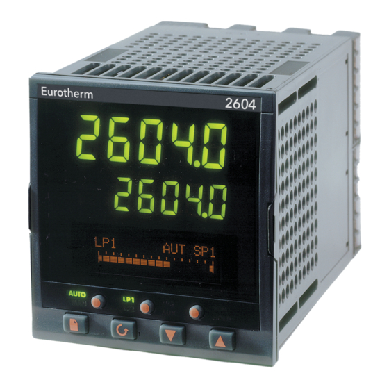
For example, there are five ‘slots’ which can contain different plug in modules. These are defined by a hardware code as shown in Appendix A. Before installing the 2604 controller check the label on the side of the instrument against the instrument coding given in Appendix A for correct type. - Page 7 ó ö € Display screen ó Latching ears ì Panel sealing gasket ö Panel retaining clips ú Label ÷ Sleeve ø Terminal covers í Ratchets Figure 1-2: General View of 2604 Controller User Guide Part No HA026491 Issue 3.0 Apr-02...
-
Page 8: Operator Interface - Overview
1.3. OPERATOR INTERFACE - OVERVIEW The front panel of the 2604 consists of two 5 digit numeric displays, one alpha numeric LCD panel for display of messages and other information, eight LED staus indicators and seven operator push-buttons. See Figure 1-3 below. -
Page 9: Led Status Indicators
Introduction 2604 Controller 1.3.1. LED Status Indicators AUTO HOLD Indicator Function AUTO The selected loop is in automatic (closed loop) control The selected loop is in manual (open loop) control Indicates which control loop is selected Indicates that the selected loop has a second control function. -
Page 10: Operator Buttons
2604 Controller Introduction 1.3.2. Operator Buttons AUTO HOLD The Auto/Manual button only operates from the loop view. When pressed, this toggles between automatic and manual mode: • If the controller is in automatic mode the Auto/Manual AUTO button AUTO light will be lit. -
Page 11: Installation - Overview
2604 Controller 1.4. INSTALLATION - OVERVIEW The 2604 controller must be mounted and wired in accordance with the instructions given in Chapter 2. The controller is intended to be mounted through a cut out in the front panel of an electrical control cabinet. - Page 12 2604 Controller Introduction 1.5. I/O MODULES The 2604 controller has the facility to fit optional plug in modules. The connections for these modules are made to the inner three connector blocks as shown in Figure 1-6 The modules are: •...
- Page 13 Introduction 2604 Controller 1-10 User Guide Part No HA026491 Issue 3.0 Apr-02...
- Page 14 2604 Controller Installation CHAPTER 2 INSTALLATION ........2 2.1. MECHANICAL INSTALLATION............2 2.1.1. Positioning ....................2 2.1.2. Outline dimensions Model 2604 ............2 2.1.3. Mounting the Controller................3 2.1.4. Unplugging and Plugging in the Controller...........3 2.2. WIRING ....................4 2.2.1. Electrical Connections................4 2.2.2. Rear Terminal Layout ................4 2.3.
-
Page 15: Chapter 2 Installation
The outline dimensions are shown in figure 2-1. Take care not to cover ventilation holes in the top, bottom and sides of the instrument. Before proceeding please read Appendix B ‘Safety and EMC Information’. 2.1.2. Outline dimensions Model 2604 Panel thickness up to 12mm, 0.5in. -
Page 16: Mounting The Controller
2604 Controller Installation 2.1.3. Mounting the Controller 1. Prepare the panel cut-out to the size shown in Figure 2-2. Ensure that there is sufficient spacing between instruments as shown by the minimum dimensions given in Figure 2-2. Ensure also that the controller is not mounted close to any device which is likely to produce a significant amount of heat which may affect the performance of the controller. -
Page 17: Wiring
It is your responsibility, as the installer, to ensure that the configuration is correct. The controller may either have been configured when ordered, or may need configuring now. See 2604 Engineering Manual Part Number HA026761 for details. -
Page 18: Appendix C
2604 Controller Installation The three central terminal strips are for optional plug in modules, as follows:- • Terminals marked 2A to 2D are reserved for a Memory Module only. No connections should be made to these terminals • Terminals marked HA to HF are connections for optional RS232, RS485, or RS422 communications modules •... -
Page 19: Standard Connections
Installation 2604 Controller 2.3. STANDARD CONNECTIONS 2.3.1. Power Supply Wiring Controllers supplied with the VH Supply Voltage option are suitable for connection to a power supply of between 85 and 264Vac 50 or 60 Hz. Controllers supplied with the VL Supply Voltage option are suitable for connection to a power supply of between 20 and 29Vac 50 or 60 Hz or 20 to 29Vdc. -
Page 20: Relay Output
2604 Controller Installation 2.3.2. Relay Output A single changeover relay is provided as standard. It can be configured as a control output or an alarm or event output. Notes: To avoid electric shock, connect the power line at the end of the wiring procedure... -
Page 21: Sensor Input Connections
Installation 2604 Controller 2.3.3. Sensor Input Connections The fixed PV input can accept a range of sensors including Thermocouple, RTD (Pt100), Pyrometer, Voltage (e.g. 0-10Vdc) or Milliamp (e.g. 4-20mA) signals. These sensors are used to provide inputs to Control Loop 1. -
Page 22: Analogue Input Connections
2604 Controller Installation 2.3.4. Analogue Input Connections The analogue input is supplied as standard and is intended to accept 0 to 10 Vdc from a voltage source. A milli-amp current source can be used by connecting a 100Ω resistor across terminals BA and BB. -
Page 23: I/O Expander (Or Additional Digital Input)
2.3.5. I/O Expander (or Additional Digital Input) An I/O expander (Model No 2000IO) can be used with the 2604 to allow the number of I/O points to be increased by a further 20 digital inputs and 20 digital outputs. Data transfer is performed serially via a two wire interface from instrument to expander. -
Page 24: Digital I/O
2604 Controller Installation 2.3.6. Digital I/O Eight digital I/O connections are provided as standard. They can be individually configured 1. Inputs Run, Hold, Reset, Auto/Manual, etc, - logic or contact closure. 2. Outputs Configurable as Control outputs, Programmer Events, Alarms, etc. -
Page 25: Optional Plug In Module Connections
OPTIONAL PLUG IN MODULE CONNECTIONS 2.4.1. Digital Communications Connections Digital Communications modules can be fitted in two positions in the 2604 controller. The connections are available on HA to HF or JA to JF depending on the position in which the module is fitted. - Page 26 2604 Controller Installation RS485 4-wire Connections ‘daisy (or RS422) chained’ to other instruments A’ (Rx+) B’ (Rx-) RS232 to RS422/RS485 HD Common 4-wire converter A(Tx+) B (Tx-) Figure 2-13: RS485 4-Wire Communications Connections Profibus Connections ‘daisy chained’ to other instruments...
-
Page 27: Devicenet Wiring
Installation 2604 Controller 2.4.2. Devicenet Wiring This section covers the DeviceNet digital communications option. To configure DeviceNet communications refer to the 2604 Engineering Handbook Part No HA026761. 2.4.2.1. DeviceNet Terminal Functions Terminal Color Description Reference Label Chip DeviceNet network power positive terminal. Connect the red wire of the DeviceNet cable here. - Page 28 2604 Controller Installation 2.4.2.2. Wiring Interconnections for DeviceNet Communications terminating 5-Position resistor required fitted COMBICOM if not internally 2604 Controller V+ 5 CAN-H 4 CAN-H Drain Drain CAN-L 2 CAN-L Card (SLAVE) Address 11 2604 Controller Diag DB-9M RDY RUN...
-
Page 29: Master/Slave Communications
Installation 2604 Controller 2.4.3. Master/Slave Communications The following diagrams show connections for a range of different controllers using RS422. These are representative of typical slaves which may be used but could also include third party products using Modbus protocol. RS422 or RS485 4-wire... - Page 30 2604 Controller Installation RS485 2-wire Slave Terminal Numbers Terminal 2200 2400 2600 2700 Function 2604 HE or JE Master HF or JF HD or JD Comms cable should be ‘daisy chained’ as shown from one 220 ohm termination instrument to the next and not connected from a ‘star’ point.
-
Page 31: I/O Modules
2604 Controller 2.4.4. I/O Modules The 2604 controller contains five positions in which 4-terminal I/O modules can be fitted. These positions are marked Module 1, Module 3, Module 4, Module 5, Module 6, in Figure 2- 3. Module 2 is reserved for the Memory Module which can only be fitted in this position. To find out which modules are fitted check the ordering code which is found on a label on the side of the instrument. - Page 32 2604 Controller Installation I/O Module Typical Connections and examples of use usage Code Triple Logic Heating, Output A cooling, Output program SSR or Output B events thyristor (18Vdc at unit Output C 8mA max. per channel) Common First triac Triac...
- Page 33 Installation 2604 Controller I/O Module Typical Connections and examples of use usage Code Dual DC Control output 12 bit Output Output 1 resolution (each channel 20V – 30V 4-20mA Can only be can be 4- fitted in 20mA or Output 2...
- Page 34 2604 Controller Installation I/O Module Typical Order Connections and examples of use usage Code 3-wire RTD Thermocouple PV Input Second or third PV (Modules 3 & 6 only) input mV, V, mA, RTD (Pt100) Zirconia probe For 2-wire this is a local link...
- Page 35 Installation 2604 Controller I/O Module Typical Order Connections and examples of use usage Code Events Triple Logic Input 1 Logic inputs Input Input 2 e.g. Program <5V OFF Run, Reset, >10.8V ON Input 3 Hold Limits: -3V, +30V Common Input 1...
- Page 36 2604 Controller Installation External calibration Provide 5V Transducer resistor (may be fitted or 10Vdc to Power in transducer). power Strain Supply Gauge Transducer Shunt Fixed Contact Module Input Note: To minimise noise pick up it is recommended that screened cables are used for strain gauge power supply connections.
-
Page 37: To Connect Zirconia (Dual Signal) Probe
Installation 2604 Controller 2.5. TO CONNECT ZIRCONIA (DUAL SIGNAL) PROBE A dual signal probe, such as a Zirconia probe, will normally be connected to a Dual PV Input module (Code DP). The module presents two channels, A and C, where A is the voltage input and C is the mV, thermocouple, RTD or mA input. -
Page 38: Zirconia Probe Screening
2604 Controller Installation 2.5.1. Zirconia Probe Screening 2.5.1.1. Zirconia Carbon Probe Construction Screen Outer Electrode Ceramic Insulator Zirc. mV Hot End Inner Electrode Thermocouple Zirconia Sensor Outer metallic shell of the probe 2.5.1.2. Screening connections when two modules are used The zirconia sensor wires should be screened and connected to the outer shell of the probe if it is situated in an area of high interference. - Page 39 Installation 2604 Controller 2-26 User Guide Part No HA026491 Issue 3.0 Apr-02...
- Page 40 2604 Controller Operation CHAPTER 3 PRINCIPLE OF OPERATION....2 3.1. POWER UP ....................3 3.1.1. The HOME Page...................3 3.2. THE OPERATOR BUTTONS ...............4 3.3. THE AUTO MANUAL BUTTON ............5 3.4. THE RUN/HOLD BUTTON ..............5 3.5. THE LOOP SELECT BUTTON ........6 3.5.1.
-
Page 41: Chapter 3 Principle Of Operation
The pages and the location of parameters within these pages follows a set order. This chapter describes how to navigate between the pages. Note: The 2604 controller is an application specific controller and can be configured to the preferences of a particular process, site or even user. This means that the displays shown in this and following chapters may not be identical to those shown in your instrument. -
Page 42: Power Up
2604 Controller Operation 3.1. POWER UP Install and wire up the controller in accordance with Chapter 2 and switch on. A short self test sequence takes place during which the controller identification is displayed together with the version number of software fitted. -
Page 43: The Operator Buttons
Operation 2604 Controller 3.2. THE OPERATOR BUTTONS AUTO HOLD When pressed, this toggles between automatic and Auto/Manual manual mode: AUTO button • If the controller is in automatic mode the AUTO light will be on • If the controller is in manual mode, the MAN light... -
Page 44: The Auto Manual Button
2604 Controller Operation 3.3. THE AUTO MANUAL BUTTON The controller has two basic modes of operation: • Automatic Mode in which the output is automatically adjusted to maintain the process value at the setpoint . • Manual Mode in which you can adjust the output independently of the setpoint. -
Page 45: Lp1 Lp3
3.5. THE LOOP SELECT BUTTON The 2604 controller can be supplied with up to three control loops. The Loop Select button allows you to select a summary of each loop from whatever page is being displayed at the time. Each press of the Loop Select button will change the display to the next loop summary. -
Page 46: To Change Setpoint (When The Loop Is In Auto)
2604 Controller Operation 3.5.1. To Change Setpoint (when the loop is in Auto) Do This This Is The Display You Additional Notes Should See From any display press the Loop Select button, > This is the loop overview , as many... -
Page 47: Parameters And How To Access Them
Engineering manual. The 2604 contains a set of default pages for most applications. It is possible to configure different start up pages as the Home page, but the principle of navigation is the same as the default pages. -
Page 48: To Step Through
2604 Controller Operation 3.6.2. To Step Through Page Headers Press - (The Page Button). At each press the first line of the alpha-numeric display will change to the name of the page header. This is a continuous list which will eventually return to the starting point, as shown in Figure 3-5 below. -
Page 49: To Step Through Parameters
Operation 2604 Controller 3.6.4. To Step Through Parameters When the page header (and sub-header) which contains the required parameter has been selected :- Press - (The Scroll Button) This will access the first parameter on the page. At each subsequent press the next parameter in the list is displayed. -
Page 50: To Change Parameter Values
2604 Controller Operation 3.6.5. To Change Parameter Values When the required parameter has been selected its value is shown in the lower part of the alpha-numeric readout. To change a parameter value press - (The Raise or Lower Buttons) If an attempt is made to change a read only parameter, the parameter value will be replaced by ------ as long as the buttons are held. - Page 51 Operation 2604 Controller Text (User definable) The first character alternates between the character and _ indicating that it can be changed :Program Name Program 1 Press to change the character. Press to change to the next character :Program Name Program 1 Press to change the character.
-
Page 52: Parameter Tables
It should also be noted that a parameter or a list of parameters can be promoted from a higher level (L3) to a lower level (L1) when the controller is configured by the user. If this has been done it will be necessary to refer to the 2604 Engineering Handbook, part number HA 026761,for further information. -
Page 53: Specific Displays For Cascade, Ratio, Override And Valve Position
Operation 2604 Controller 3.7. SPECIFIC DISPLAYS FOR CASCADE, RATIO, OVERRIDE AND VALVE POSITION When the loop select button is pressed the upper and middle readouts generally show PV and SP, see section 3.5. If the loops are configured as Cascade, Ratio, Override or Motor Valve... -
Page 54: Loop Summary Parameters
2604 Controller Operation 3.7.1. Loop Summary Parameters When the Loop Select Button is pressed a summary of the loop is displayed as shown in Figure 3-3. Press button to access up to 10 additional parameters which may have been promoted, in configuration level, to the loop summary page. -
Page 55: Backpage
Operation 2604 Controller 3.8. BACKPAGE When stepping through list headers, a backpage short cut is provided by holding down and press . Each press of will step back one position of the list header in a continuous loop. This function is provided as a short cut and is not necessary to navigate through the pages. -
Page 56: Parameter Availability And Alterability
Any one or all of the pages shown in the navigation diagram can also be displayed at Level 1 & 2. This, however, will have been pre-set in Configuration Level (see 2604 Engineering Manual Part No HA026761). - Page 57 Operation 2604 Controller 3-18 User Guide Part No HA026491 Issue 3.0 Apr-02...
- Page 58 2604 Controller Programmer Operation CHAPTER 4 PROGRAMMER OPERATION ..... 2 4.1. CUSTOMISABLE PARAMETER NAMES .........2 4.2. WHAT IS SETPOINT PROGRAMMING ? ........3 4.3. SETPOINT PROGRAMMER DEFINITIONS ........4 4.3.1. Run......................4 4.3.2. Hold ......................4 4.3.3. Reset......................4 4.3.4. Servo .....................4 4.3.5. Hot Start ....................4 4.3.6.
-
Page 59: Chapter 4 Programmer Operation
Parameters which are associated with setpoint program operation are also listed in tables as a general reference. Note: The 2604 controller is an application specific controller and can be configured to the preferences of a particular process, site or even user. This means that the displays shown in this and following chapters may not be identical to those shown in your instrument. -
Page 60: What Is Setpoint Programming
- and containing details for each profiled setpoint. The total number of segments available is 100 per program with a maximum of 500. The 2604 programmer may store up to 20 programs as standard, with up to 50 if purchased, and works on a single timebase for all programs. -
Page 61: Setpoint Programmer Definitions
Programmer Operation 2604 Controller 4.3. SETPOINT PROGRAMMER DEFINITIONS This section defines the more common parameters to be found when running a 2604 programmer /controller. For an explanation of further features see the Engineering Handbook part no HA026761. 4.3.1. Run In run the programmer varies the setpoint in accordance with the profile set in the active program. -
Page 62: Holdback (Guaranteed Soak)
2604 Controller Programmer Operation 4.3.7. Holdback (Guaranteed Soak) Holdback freezes the program if the process value (PV) does not track the setpoint (SP) by an amount that can be set by the user. It may operate in any PSP type. -
Page 63: Wait
Programmer Operation 2604 Controller 4.3.9. Wait An event can be configured at the end of each segment, which, when active, will cause the program to wait before progressing to the next segment. Three wait conditions are provided which may be wired, in configuration level, to an external source using digital inputs or to internal sources, e.g. -
Page 64: Programmer Types
2604 Controller Programmer Operation 4.4. PROGRAMMER TYPES The programmer can be configured as Time to Target or Ramp Rate. A time to target programmer requires fewer settings and is simple to use since all segments are the same. A time to target programmer can, in general contain more segments than a ramp rate. -
Page 65: Go Back Segment
Programmer Operation 2604 Controller 4.5.2. Go Back Segment Go Back allows segments in a program to be repeated by a set number of times. It is the equivalent of inserting ‘sub-programs’ on some controllers. Figure 4-4 shows an example of a program which is required to repeat the same section a number of times and then continue the program. -
Page 66: Programmer Operation
2604 Controller Programmer Operation 4.7. PROGRAMMER OPERATION 4.7.1. To Run, Hold or Reset a Program A selected program may be run, reset or held as follows: 1. Press the RUN/HOLD button once, the RUN beacon will illuminate. Press the RUN/HOLD button again, the HOLD beacon will illuminate. Press and hold the RUN/HOLD button for 3 seconds, the program will reset and both beacons will extinguish. -
Page 67: Run Parameters
Programmer Operation 2604 Controller 4.7.2. Run Parameters The Run list provides status information on a running program, as follows:- Table Number: These parameters show the status of the PROGRAM RUN overall program (General Page) 4.7.2a. Parameter Parameter Description Value Default... - Page 68 2604 Controller Programmer Operation Seg Time Rem Time remaining in the current d: h: m: s L1. Read or segment alterable if Time To Target prog and in Hold Wait Status Wait Status No Wait Event A Event B Event C...
- Page 69 Programmer Operation 2604 Controller Table Number: These parameters are associated with PROGRAM RUN Profiled Setpoint number 1 4.7.2b. (PSP1 Page) Parameter Name Parameter Description Value Default Access Level Seg Time Rem Segment time remaining h: m: s PSP1 Type Running segment type for...
- Page 70 2604 Controller Programmer Operation Table Number: These parameters are associated with PROGRAM RUN PSP2 and only appear if PSP2 is 4.7.2c (PSP2 Page) configured Parameter Name Parameter Description Value Default Access Level Seg Time Rem Segment time remaining h: m: s...
-
Page 71: To Create Or Edit A Program
Programmer Operation 2604 Controller Table Number: These parameters are associated with PROGRAM RUN PSP3 and only appear if PSP3 is 4.7.2d (PSP3 Page) configured Parameter Name Parameter Description Value Default Access Level Seg Time Rem Segment time remaining h: m: s... -
Page 72: To Define Parameters Common To A Program
2604 Controller Programmer Operation 4.8.1. To Define Parameters Common To A Program Do This This Is The Display You Additional Notes Should See From any display press The PROGRAM EDIT as many times as :PROGRAM EDIT page is not available in... -
Page 73: Program Edit (Program Page) Parameters
Programmer Operation 2604 Controller 4.8.2. PROGRAM EDIT (Program Page) Parameters Table These parameters affect the overall PROGRAM EDIT Number: program. Only shown at Level 3. (Program Page) 4.8.2 Parameter Parameter Description Value Default Access Level Name Edit Prg: 1 Selects the program... - Page 74 2604 Controller Programmer Operation Hot Start Allows hot start to be None None L3. Only applied to each PSP. appears if Hot PSP1 Start option has See also 6.2.5. PSP2 been enabled in config level. PSP3 Rate Units Rate units for a Ramp Per Second L3.
-
Page 75: To Set Up Each Segment Of A Program
Programmer Operation 2604 Controller 4.8.3. To Set Up Each Segment Of A Program Do This This Is The Display You Additional Notes Should See From any display press This page allows each : PROGRAM EDIT segment to be edited. as many times as... -
Page 76: Program Edit(Segment Page) Parameters
2604 Controller Programmer Operation 4.8.4. PROGRAM EDIT(Segment Page) Parameters Table Number: These parameters allow you to set up PROGRAM EDIT each segment in the program 4.8.4. (Segment Page) Parameter Parameter Description Value Default Access Name Level Edit Prg: 1 Selects the program number... - Page 77 Programmer Operation 2604 Controller The above five parameters are repeated for PSP2 and PSP3 if they are configured Seg Duration Duration for Time to Target d : h : m : s L1. Does programmer not appear for Ramp Rate...
-
Page 78: Examples
2604 Controller Programmer Operation 4.9. EXAMPLES 4.9.1. Program Data Entry Example in a Ramp Rate Programmer Do This The Display You Should See Additional Notes Select the PROGRAM :PROGRAM EDIT EDIT (Segment Page) Segment Page Press to select Edit The name of the program... - Page 79 Programmer Operation 2604 Controller If PSP 2 is configured, steps 4 to 7 are repeated for PSP2. If PSP 3 is configured, steps 4 to 7 are again repeated for PSP3. If Wait Events are configured:- The choice are:- 14. Press...
-
Page 80: Prog Data Entry Example - Time To Target Programmer
2604 Controller Programmer Operation 4.9.2. Prog Data Entry Example - Time to Target Programmer This is the same as the previous procedure except that there are no Dwell, Rate or Step segments. They are all Time segments. From the PROGRAM EDIT (segment Page) header:-... -
Page 81: Holdback Example
Programmer Operation 2604 Controller 4.9.3. Holdback Example To apply holdback (see also 6.2.8) to each segment of the program or to the overall program, follow this procedure:- Do This This Is The Display You Additional Notes Should See Select the PROGRAM EDIT... -
Page 82: Wait Example
2604 Controller Programmer Operation 4.9.4. Wait Example The wait feature prevents the programmer from proceeding to the next segment if an event is true (see also section 4.3.9.). It only applies to controllers which have been ‘wired’ for wait events in configuration level. If the controller has been configured for ‘Wait’, the operator can... - Page 83 Programmer Operation 2604 Controller 4.9.4.1. Wait Example - How Wait is Displayed in Run Mode The status of the Wait condition is displayed in a running program as follows:- Do This This Is The Display You Additional Notes Should See...
-
Page 84: Program Names Example
2604 Controller Programmer Operation 4.9.5. Program Names example To produce a user defined program name:- Do This This Is The Display You Additional Notes Should See Select the PROGRAM :PROGRAM EDIT EDIT (Program Page) Program Page page header Press until Program... - Page 85 Programmer Operation 2604 Controller 4-28 User Guide Part No HA026491 Issue 3.0 Apr-02...
- Page 86 CHAPTER 5 ALARM OPERATION ......2 5.1. DEFINITION OF ALARMS AND EVENTS........2 5.1.1. Customisable Parameter Names ............2 5.2. TYPES OF ALARM USED IN 2604 CONTROLLER......3 5.2.1. Grouped Alarms ..................4 5.3. HOW ALARMS ARE INDICATED............5 5.3.1. To Acknowledge an Alarm ..............5 5.3.2.
-
Page 87: Chapter 5 Alarm Operation
Alarm Operation 2604 Controller 5. Chapter 5 ALARM OPERATION 5.1. DEFINITION OF ALARMS AND EVENTS Alarms are used to alert an operator when a pre-set level has been exceeded. They are normally used to switch an output – usually a relay – to provide external actions to the process. -
Page 88: Types Of Alarm Used In 2604 Controller
2604 Controller Alarm Operation 5.2. TYPES OF ALARM USED IN 2604 CONTROLLER This section shows graphically the operation of different types of alarm used in the controller. The graphs show changes in PV plotted against time. Alarm Type Full Scale... -
Page 89: Grouped Alarms
On a new controller these are the only alarms which are configured - those listed below must be enabled in configuration level, see 2604 Engineering Handbook HA026761. Alarms which operate on the PV input. Examples are: High and PV Input Alarms Low. -
Page 90: How Alarms Are Indicated
2604 Controller Alarm Operation 5.3. HOW ALARMS ARE INDICATED When an alarm occurs the red ALM beacon in the middle display will flash. This will be accompanied by a message on the lower display which will indicate the source and the type of alarm. -
Page 91: Alarm Delay Time
To set delay time the controller must be placed in Configuration level. This is described in the 2604 Engineering Handbook Part No HA026761. If you notice a delay between an alarm occurring and it being indicated by the controller then a delay may have been set in configuration level. - Page 92 2604 Controller Alarm Operation 5.4. THE ALARM SUMMARY PAGE The status of alarms is displayed in the Alarm Summary page. To inspect the status: Do This This Is The Display You Additional Notes Should See From any display press To access the Alarm :ALARMS Summary page header.
-
Page 93: Alarms (Summary) Parameters
Alarm Operation 2604 Controller 5.4.1. Alarms (Summary) Parameters Table Number: These parameters indicate alarm status ALARMS 5.4.1 (Summary Page) Parameter Name Parameter Description Value Default Access Level New Alarm Only available over digital L1 R/O communications to flag that Y e s... -
Page 94: Alarm Acknowledgement
2604 Controller Alarm Operation 5.5. ALARM ACKNOWLEDGEMENT A new alarm can be acknowledged in five ways: 1. By pressing simultaneously 2. Through the alarms ‘Summary’ page 3. Through the ‘Alarms’ page 4. From an external source, such as a pushbutton, connected to a suitably configured digital input 5. - Page 95 Alarm Operation 2604 Controller Latched Alarm - Manual Alarm Acknowledge Symbol Message Ext relay Condition (if fitted) Flashing Alarm message Flashing Alarm message Access Level Alarm Acknowledge Symbol Message Ext relay Condition (if fitted) Flashing Alarm message Steady Former display...
-
Page 96: To Set Alarm Trip Levels
2604 Controller Alarm Operation 5.6. TO SET ALARM TRIP LEVELS The alarm trip level (setpoint) is available in access level 1 and is adjusted by accessing the page header for the chosen alarm. The following example adjusts these parameters for Alarm... -
Page 97: Alarm Parameters
Alarm Operation 2604 Controller 5.7. ALARM PARAMETERS The parameter tables listed in this section are only displayed if an alarm has been configured for the particular loop, input or module. 5.7.1. ALARMS ( LP1 Page) Parameters Table Number: These parameters set up the Loop 1 alarms ALARMS 5.7.1. -
Page 98: Alarms (Pv Input Page) Parameters
2604 Controller Alarm Operation 5.7.2. ALARMS (PV Input Page) Parameters Table Number: These parameters set up the alarms ALARMS associated with the PV input signal. 5.7.2. (PV Input Page) Parameter Name Parameter Description Value Default Access Level PV Alarm Ack... - Page 99 Alarm Operation 2604 Controller 5.7.4. ALARMS (Module 1 Page) Parameters Table Number: These parameters set up the alarms ALARMS associated with module 1. 5.7.4. (Module 1 Page) Parameter Name Parameter Description Value Default Access Level Module 1 Ack Group alarm acknowledge...
- Page 100 2604 Controller Appendix A APPENDIX A ORDER CODE ........2 A.1. HARDWARE CODE ................2 A.2. CONFIGURATION CODING (OPTIONAL) ........3 A.3. QUICK START CODE EXAMPLE:.............4 User Guide. Part No HA026491 Issue 3.0 Apr-02...
- Page 101 A. Appendix A Order Code A.1. HARDWARE CODE The 2604 has a modular hardware construction, which accepts up to six plug-in modules and two comms modules. Eight digital IO and a relay form part of the fixed hardware build. Controller Type...
- Page 102 2604 Controller Appendix A A.2. CONFIGURATION CODING (OPTIONAL) The controller supplied in accordance with the hardware code on the previous page requires to be configured. Configuration is carried out using iTools. Alternatively, for simple applications the controller may be supplied pre-configured using the following code:-...
- Page 103 Appendix A 2604 Controller General Notes 1. Loop 1 PV defaults to main input on microboard. Loop 2 and 3 PV inputs must be fitted in I/O slots 3 or 6 or be assigned to the analogue input. 2. This alarm configuration refers to loop alarms only. One selection per loop is allowed.
- Page 104 2604 Controller Safety and EMC Information B. APPENDIX B SAFETY AND EMC INFORMATION ... 2 B.1. SAFETY .......................2 B.1.1. Electromagnetic compatibility ..............2 B.2. SERVICE AND REPAIR................2 B.2.1. Electrostatic discharge precautions.............2 B.2.2. Cleaning......................2 B.3. INSTALLATION SAFETY REQUIREMENTS........3 B.3.1. Safety Symbols ...................3 B.3.2.
-
Page 105: Appendix B Safety And Emc Information
2604 Controller Appendix B Safety and EMC Information This controller is manufactured in the UK by Eurotherm Controls Ltd. Please read this section carefully before installing the controller This controller is intended for industrial temperature and process control applications when it will meet the requirements of the European Directives on Safety and EMC. -
Page 106: Installation Safety Requirements
2604 Controller Safety and EMC Information B.3. INSTALLATION SAFETY REQUIREMENTS B.3.1. Safety Symbols Various symbols are used on the instrument, they have the following meaning: Caution, (refer to the Functional earth accompanying documents) (ground) terminal The functional earth connection is not required for safety purposes but to ground RFI filters. -
Page 107: Wiring
Safety and EMC Information 2604 Controller Analogue Input Digital Input 220K Control Digital IO Voltage 220K Common Voltage 2.5V Instrument Ground Screen 100R Fuse Bleed Resistor Resistor Figure B-1: Analogue Input and Fixed Digital I/O Equivalent Circuit B.3.5. Wiring It is important to connect the controller in accordance with the wiring data given in this handbook. -
Page 108: Overcurrent Protection
2604 Controller Safety and EMC Information B.3.8. Overcurrent protection To protect the internal PCB tracking within the controller against excess currents, the AC power supply to the controller and power outputs must be wired through the fuse or circuit breaker specified in the technical specification. -
Page 109: Over-Temperature Protection
Safety and EMC Information 2604 Controller B.3.11. Over-temperature protection When designing any control system it is essential to consider what will happen if any part of the system should fail. In temperature control applications the primary danger is that the heating will remain constantly on. - Page 110 2604 Controller Technical Specification APPENDIX C TECHNICAL SPECIFICATION ... 2 C.1. ALL ANALOGUE, DUAL AND PV INPUTS ........2 C.2. PRECISION PV INPUT / MODULE ............3 C.3. DUAL (PROBE) INPUT MODULE ............3 C.4. ANALOGUE INPUT................4 C.5. ANALOGUE INPUT MODULE............4 C.6. STANDARD DIGITAL I/O ..............5 C.7.
-
Page 111: Appendix C Technical Specification
Technical Specification 2604 Controller Appendix C Technical Specification All figures quoted at 0 to 50 C unless otherwise stated. C.1. ALL ANALOGUE, DUAL AND PV INPUTS Sample rate 9Hz (110msec.) Input filtering OFF to 999.9 seconds of filter time constant (f.t.c.). Default setting is 0.4 seconds unless stated otherwise... -
Page 112: Precision Pv Input / Module
2604 Controller Technical Specification C.2. PRECISION PV INPUT / MODULE Allocation One standard and up to two additional PV input modules can be fitted (isolated) in I/O slots 3 and 6 mV input Two ranges: ±40mV & ±80mV, used for thermocouple, linear mV source or 0 - 20mA with 2.49W... -
Page 113: Analogue Input
Technical Specification 2604 Controller C.4. ANALOGUE INPUT No of inputs One fixed (Not isolated) Can be used with either floating or ground referenced transducers of low impedance. Input range -10V to +10V linear or 0 -20 mA with burden resistor of 100W. -
Page 114: Standard Digital I/O
2604 Controller Technical Specification C.6. STANDARD DIGITAL I/O Allocation 1 digital input standard and 7 I/O which can be configured as inputs or not isolated outputs plus 1 changeover relay Digital inputs Voltage level : input active < 2Vdc, inactive >4Vdc Contact closure : input active <100ohms, inactive >28kohms... -
Page 115: Transducer Psu
Technical Specification 2604 Controller C.11. TRANSDUCER PSU Bridge voltage Software selectable 5 or 10Vdc Bridge resistance 300Ω to 15KΩ Internal shunt 30.1KΩ at 0.25%, used for calibration of 350Ω bridge resistor C.12. DUAL DC OUTPUT Current Output 4-20mA, 20V output span... -
Page 116: User Messages
2604 Controller Technical Specification C.17. USER MESSAGES No of messages Maximum 50, triggered by operator or alarm or used for custom parameter names Format Up to 16 characters C.18. CONTROL FUNCTIONS No of loops One, two or three Modes On/off, PID, motorised valve with or without feedback... -
Page 117: General Specification
Technical Specification 2604 Controller C.21. GENERAL SPECIFICATION Display range 5 digits including up to 3 decimal places Supply 85-264Vac, 20Watts (max) Operating ambient 0 - 50°C and 5 to 95% RH non condensing Storage temp -10 to +70°C Panel sealing... -
Page 118: Graphical Representation Of Errors
2604 Controller Technical Specification C.22. GRAPHICAL REPRESENTATION OF ERRORS This section shows graphically the effects of adding all contributions of different errors for each input type and range. The errors are a combination of: Calibration accuracy, Drift with ambient temperature, Linearity error, Leakage C.22.1. -
Page 119: Mid Range High Impedance Input
Technical Specification 2604 Controller Mid range high impedance Input C.22.2. 0 - 2V Input type Range: working range -1.4V to +2V full linear range -1.8V to +2.4V noise (resolution) 100uV - OFF, 50uV - 0.4sec, 35uV - 1.6sec Calibration accuracy @ 25 <... -
Page 120: High Level Input
2604 Controller Technical Specification High Level Input C.22.3. 0 - 10V Input type Range: working range -3V to +10V full linear range - 5V to +14V noise (resolution) 300uV - OFF, 150uV - 0.4sec, 100uV - 1.6sec Calibration accuracy @ 25 <... -
Page 121: Rtd (Pt-100) Input Type
Technical Specification 2604 Controller RTD (Pt-100) Input type C.22.4. Resistance measurement specification in Ohms: Range 0 to 400Ω with up to 22Ωin each connecting lead Noise (resolution) 8mΩ - 0.4sec, 4mΩ - 1.6sec Calibration accuracy limits @ 25 < + (35mΩ @110Ω + 0.03% of |reading - 110Ω|) Drift with ambient temperature + (0.002% of |reading|) per... - Page 122 2604 Controller Technical Specification | Error | Specified limit of max. errors at 0 to 50 The actual and typical errors at 0 to 50 Specified limit of max. error at ambient 25 The actual maximum error at ambient 25...
-
Page 123: Thermocouple Input Type
Technical Specification 2604 Controller C.22.5. Thermocouple Input type Internal CJT sensing spec Calibration error @ 25 C (including temp. difference between top and bottom screws) < + 0.5 Total CJT error < + (0.5 C + 0.012 C per 1 C of ambient change) ( i.e.
Need help?
Do you have a question about the 2604 and is the answer not in the manual?
Questions and answers