Sign In
Upload
Manuals
Brands
Eurotherm Manuals
Controller
2500
Eurotherm 2500 Manuals
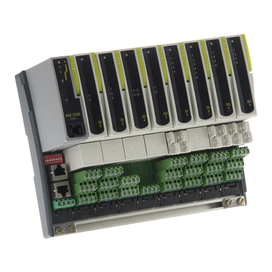
Manuals and User Guides for Eurotherm 2500. We have
1
Eurotherm 2500 manual available for free PDF download: Engineering Handbook
Eurotherm 2500 Engineering Handbook (224 pages)
Brand:
Eurotherm
| Category:
Controller
| Size: 4 MB
Table of Contents
Table of Contents
3
SAFETY and EMC INFORMATION
10
Chapter 1 INTRODUCTION
13
About this Handbook
13
Symbols Used in this Manual
13
File Paths
13
Status Words
14
What Is the 2500
15
What Does the 2500 Do
15
The Components of the 2500
16
Unpacking the Instrument
16
Mechanical Installation
17
DIN Rail Mounting
18
Panel Mounting
18
Terminal Unit Installation
18
Terminal Unit Removal
18
To Fit a Module
19
Module Removal
19
I/O Module Functions
20
Chapter 2 The IOC Module
21
Overview
21
Operating Modes
22
Run Mode
22
Configuration Mode
22
Configuration Key
23
Standby Mode
23
Fail Mode
23
Configuration Port
24
Status Indication
25
Initialisation and Power on Self Test
26
Modbus Ioc and Terminal Unit
27
Connections to the RJ45 Sockets
27
The RJ45 Modbus Line Terminator
28
The Modbus Address Switch
28
Baud Rate
28
Profibus Ioc and Terminal Unit
29
Connections to the Network Connectors
30
The Profibus Address Switch
30
Profibus 9 Pin Connector Line Termination
31
The RJ45 Profibus Line Terminator
31
Devicenet Ioc and Terminal Unit
32
Connections to the Terminal Unit
33
Devicenet Terminators
33
Power
33
The Devicenet Address Switch
33
Ethernet Ioc and Terminal Unit
34
Connections to the RJ45 Socket
35
The Modbus Address Switch
35
Chapter 3 Itools
36
Overview
36
Connecting any 2500 to a Personal Computer
36
To Connect a Single 2500 Controller to a PC
36
To Connect Multiple 2500 Controllers to a PC
37
Starting Itools - Device Detection
40
Setting Access Level
40
Operating Mode
40
Configuration Mode
40
Standby Mode
41
Changing Mode
41
Instrument Parameters
42
To Display Parameters
42
To Find a Parameter
42
To Change Parameter Values
43
Example: to Set Baud Rate
43
Failure to Write a New Value
43
Parameter Availability and Alterability
44
Setting up an Application
45
What Is a Function Block
45
Why Use Function Blocks
45
Function Block Wiring Example
45
Declaring I/O Modules
47
The Wiring Editor
47
Chapter 4 Control
48
About this Section
48
Loop View
48
Loop Overview Parameters
49
Loop Configuration
50
Key Configuration Parameters
50
Other Loop Configuration Parameters
51
Pid Control
52
Proportional Term
52
Integral Term
52
Derivative Term
52
High and Low Cutback
53
PID Block Diagram
53
PID Parameters
54
Gain Scheduling
56
Gain Scheduling Parameters - PID Sets
56
Loop Setpoint
58
Setpoint Parameters
58
Rate Limit and Holdback Parameters
59
Remote Setpoint Parameters
60
Control Setpoint - Ramp Parameters
60
Loop Setpoint Configuration
61
Setpoint Function Block
61
Setpoint Configuration Parameters
62
Control Output
63
Output Function Block
63
Output Parameters
63
Valve Control Outputs
65
Valve Control Parameters
65
Ratio Control
66
Basic Ratio Control
66
Ratio Parameters
66
Cascade
68
Overview
68
Trim Mode
68
Auto/Manual Operation in Cascade
68
Cascade Controller Block Diagram
68
Cascade Parameters
69
Override
71
Override Parameters
72
Tuning
73
Automatic (One-Shot) Tuning
73
Autotune Parameters
73
Cascade Tuning
75
Example: to Tune a Full Scale Cascade Loop
75
Loop Diagnostics
77
Loop Status Word
77
Loop Alarms
77
Chapter 5 Alarms
78
Definition of Alarms and Events
78
Types of Analogue Alarm Used in the 2500
78
Absolute High
78
Absolute Low
78
Deviation High Alarm
79
Deviation Low Alarm
79
Deviation Band
79
Rate of Change Alarm
80
Types of Digital Alarm Used in the 2500
81
Blocking Alarms
81
Absolute Low with Blocking
81
Absolute High Alarm with Blocking
81
Deviation Band with Blocking
82
Latching Alarms
82
Latched Alarm (Absolute High) with Automatic Reset
82
Latched Alarm (Absolute High) with Manual Reset
83
Groups & Alarm Status Word
83
Loop Alarms
83
Alarm Parameters
84
User Alarms
85
User Alarm Parameters - Analogue
85
User Alarm Parameters - Digital
85
I/O Alarms
86
I/O Alarm Parameters
86
Analogue Modules
86
Digital Modules
86
Instrument Status Alarms
87
Individual Channel Status
87
Status of All Channels in a Module
87
Status of All Channels in a System (IOC)
88
Module Status
88
System (IOC) Status
88
Chapter 6 Operator
89
Linearisation Tables
89
Digital Communications
89
Digital Communications Parameters
90
System
93
System Parameters
93
Password Entry
97
Password Entry Parameters
97
Password Set up
97
Password Set up Parameters
97
Diagnostics
97
Diagnostic Parameters
97
System Descriptions
98
Chapter 7 I/O MODULES
99
Overview
99
I/O Blocks
99
I/O Module Indicator Leds
100
Channel Isolation
101
Channel Status and Errors
102
Io Module Configuration Concepts
103
Module Block Parameters
103
Module Channel Parameters
106
Analogue Input Modules
107
AI2 Isolation Barriers
107
AI2 Analogue Input Equivalent Circuits
107
AI2 Terminal Connections
109
AI3 Isolation Barriers
110
AI3 Ma Input Equivalent Circuit
110
AI3 Terminal Connections
110
AI3 Analogue Input Module Hart Compatibility
110
AI4 Isolation Barriers
111
AI4 Analogue Input Equivalent Circuits
111
AI4 Terminal Connections
112
Analogue Input Parameters
112
Analogue Output Module
116
Analogue Output Isolation Barriers
116
Analogue Output Equivalent Circuits
116
AO Terminal Connections
116
Analogue Output Channel Parameters
117
Digital Input Modules
119
Di4
119
DI4 Channel Isolation Barriers
119
DI4 Digital Input Equivalent Circuits
119
DI4 Terminal Connections
119
DI6 115V and 230V
120
DI6 Isolation Barriers
120
DI8 Logic
121
DI8 Logic Input Isolation Barriers
121
DI8 Equivalent Circuits
121
DI8 Terminal Connections
121
DI8 Contact Input
122
Digital Input Parameters
122
Digital Output Modules
124
DO4 EP (External Power)
124
DO4 EP Channel Isolation
124
Digital Output Equivalent Circuits
124
DO4 Terminal Connections
124
Do4 24V
124
Relay Module RLY4
125
RLY4 Isolation Barriers
125
RLY4 Terminal Connections
125
RLY4 Snubber Circuits
125
Digital Output Channel Parameters
126
Configuration Examples
128
Thermocouple or RTD Input
128
Pyrometer Input
128
Analogue Input: MV, Ma, V, Ohms
129
Analogue Output
130
Digital Input
131
Digital Outputs
132
Valve Position Controller
133
To Calibrate a Potentiometer Input
134
Chapter 8 Toolkit Blocks
135
Overview
135
Analogue Blocks
135
Analogue Operators
136
Analogue Block Parameters
137
Digital Blocks
139
Logic Operators
139
Parameters for Digital Blocks
139
Example - to Produce a Logic Calculation Block
141
User Values
142
Timer Blocks
143
Timer Types
143
On Pulse Timer Mode (PULSE)
143
Off Delay Timer Mode (DELAY)
144
One Shot Timer Mode (1 SHOT)
145
Minimum on Timer Mode (CMPRSS)
146
Timer Parameters
147
Counters
148
Counter Parameters
148
Totalisers
150
Totaliser Parameters
150
Wiring
152
An Example of Soft Wiring
152
Point to Point Wiring
153
WIRES Parameters
153
Relative Humidity
154
Overview
154
Humidity Parameters
154
Zirconia - Carbon Potential Control
155
Overview
155
Zirconia Probe Parameters
155
Temperature Control
157
Carbon Potential Control
157
Endothermic Gas Correction
157
Sooting Alarm
157
Automatic Probe Cleaning
158
Order in Which Calculations Are Performed
158
Chapter 9 Modbus Communications
159
Overview
159
Modbus Addresses
159
Offset
159
Parameter Addresses
159
Parameter Resolution
159
Floating Point
159
Communications Blocks
160
Block Communications
160
Indirection Tables
160
Read Write Source Indirection Table
160
Read Write Value Indirection Table
160
Read Only Indirection Table
160
Chapter 10 Profibus Communications
161
Overview
161
Profibus Installation
161
Configuration of the 2500 for Profibus
161
A 'Gsd' File
161
To Create a New Gsd File
162
To Save the Gsd File
163
Operating and Application Notes
164
Chapter 11 Devicenet Communications
165
Overview
165
Default Mapping
165
2500 Default Parameter Mapping
165
Custom Parameter Mapping
166
Indirection Tables
166
Read Write Indirection Table
166
Read Only Indirection Table
166
Chapter 12 Ethernet Communications
167
Overview
167
Support for Other Ethernet Utilities
167
Configuration of the 2500 for Ethernet
168
General
168
Setting the Instrument Address
168
DIP Switches
168
Ethernet Communications Parameters
169
Unit Ident Enable
169
IP Address
169
Subnet Mask
170
Default Gateway
170
Preferred Master - Multiple Connections
170
MAC Address
171
Dynamic Host Configuration Protocol
171
Modbus Exceptions
172
Communications Indicators
172
Modbus Communications Indicator
172
Ethernet Communications Indicators
172
Network Watchdog
172
Chapter 13 Calibration
173
Overview
173
Simple Offset
173
To Perform Offset Calibration
174
User Calibration
174
To Perform User Calibration
175
Reference Calibration
176
Analogue Input Calibration Procedure
177
Analogue Output Calibration Procedure
178
Restore Factory Calibration
178
Appendix A SPECIFICATION
179
Appendix B the Ordering Codes
187
Appendix C to Remove Snubber Circuits from the Relay Module
194
Appendix D Glossary of Terms
196
Index
197
Index - Key Words
221
Advertisement
Advertisement
Related Products
Eurotherm Invensys 2408
Eurotherm Invensys 2404
Eurotherm 2704
Eurotherm 2604
Eurotherm 2416
Eurotherm 2116i
Eurotherm 2216e
Eurotherm 2204e
Eurotherm 2116
Eurotherm 2132
Eurotherm Categories
Controller
Temperature Controller
Voice Recorder
Measuring Instruments
DC Drives
More Eurotherm Manuals
Login
Sign In
OR
Sign in with Facebook
Sign in with Google
Upload manual
Upload from disk
Upload from URL