Table of Contents
Advertisement
Advertisement
Table of Contents

Related Manuals for Eurotherm EFit


Summary of Contents for Eurotherm EFit
- Page 1 EFit User Guide Power Controller HA031980ENG issue 1 February 2014...
- Page 3 In order to maintain its ‘leading edge’ Eurotherm may have to make changes to its specifications without advance notice. For any further information, or if in doubt, please contact Invensys Eurotherm, where qualified staff are available to advise or assist you with the commissioning of your installation.
- Page 4 EFit User Manual...
-
Page 5: Table Of Contents
5.2.2 View on upper face 6. Control wiring 6.1 Input signal wiring 6.1.1 Remote Control 6.1.2 Local control by potentiometer 6.1.3 Local control by contacts 6.2 Auxiliary power supply (option) 7. Current limit option 7.1 Operations 7.2 Adjustment EFit User Manual... - Page 6 8. Thyristors firing modes 8.1 Fast cycle 8.2 Single-cycle 8.3 Advanced Single-cycle 8.4 Phase angle 9. Power control 9.1 Description 9.2 Compensation of power supply fluctuations 10. Current derating EFit User Manual...
-
Page 7: Safety Notes
National Electric Code (NEC) requirements. If opening of the branch circuit protective or the supplemental fuses (high speed fuse) EFit shall be examined and replaced if damaged. It is strongly recommended that the installing authority includes independent, system-safety mechanisms to protect both personnel and equipment against injury or damage, and that such safety mechanisms be regularly inspected and maintained. - Page 8 The cabinet must be closed under normal operating conditions. Adequate air conditioning/ filtering/ cooling equipment must be fitted to the cabinet in order to prevent the ingress of conductive pollution, the formation of condensation etc. EFit User Manual...
- Page 9 8. This product has been designed for environment A (Industrial). Use of this product in environment B (domestic, commercial and light industrial) may cause unwanted electromagnetic disturbances in which cases the user may be required to take adequate mitigation measures. EFit User Manual...
-
Page 10: Selv
AC supply only must be taken when handling this unit Underwriters Laboratories listed Refer to the manual for instructions mark for Canada and the US Do not touch Heatsink Declaration of conformity Hot Surface to European standard EFit User Manual... -
Page 11: Technical Specifications
Compulsory Certification Protection IP20 According to EN60529 - CE, Open type - UL Installation Category Rated impulse Rated Installation withstand voltage insulated Category (U imp) voltage (Ui) Control 0,5kV 0,8kV Auxilary Supply 2,5kV 230V Power terminals 500V EFit User Manual... - Page 12 100V to 500V (+10%/–15%). Refer to ‘Codification’ for more details Frequency 47Hz to 63Hz Rated short-circuit 100KA (coordination type 1) (see 3.2) conditional current Type of loads AC51 Pure resistive AC-56a Transformer Primary (Phase Angle product only with current limit) EFit User Manual...
- Page 13 Automatic compensation for supply fluctuation (variation: between -10% and +10% of the nominal voltage). Firing modes Burst - Burst variable (16 periods) - Single cycle - Advanced single cycle Phase angle - With or Without current limit EFit User Manual...
-
Page 14: Codification
440 volts 440V With current limit 480 volts 480V (only with PA) 500 volts 500V Fuse Input Without fuse NOFUSE 0-5Vdc With fuse without FUSE 4-20mA 4mA20 microswitch 0-10V 0V10 With fuse with MSFUSE microswitch See 3.2 EFit User Manual... -
Page 15: Fuses
3.2 Fuses According to the CE and UL certifications, high speed fuses are necessary for the protection of the EFit power controller against short circuit. The power circuit shall be protected by a supplemental fuse as described in the table below. These should be used in conjunction with suitable fuse holders and contact kits (if required) as shown in this table. -
Page 16: Mechanical Installation
92,5 92,5 122,5 92,5 Minimum spacing (width) between two EFit units: - 10mm up to 45°C (ambient temperature) Safety earth: For EMC compliance ensure that the DIN rail is electrically bonded to the reference ground (panel or bulkhead) EFit User Manual... -
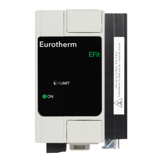
Page 17: Front Fascia
(available as an option only in Phase Angle) Green led thyristor firing indicator 2/T1 4/T2 Plug-in control connector (input) Load terminals Safety earth (M5 nut). The earth connection must be made using a Listed ring type crimp. FRONT FASCIA EFit User Manual... -
Page 18: Electrical Installation
‘+’ of control signal Plug-in (24 to 12 (5.31 Lb.In) x3,5mm AWG) rated User 5V 75°C 8 & 10 Auxiliary power supply 0.5 to (option) 1.5mm 0.25N.m Plug-in (24 to 14 (2.25 Lb.In) x2,5mm Not used AWG) rated 75°C EFit User Manual... -
Page 19: Connector View
5.2 Connectors 5.2.1 View on lower face Load terminals Control 2/T1 4/T2 input Auxiliary power supply 5.2.2 View on upper face Mains terminals 1/L1 3/L2 EFit User Manual... -
Page 20: Control Wiring
6. Control wiring 6.1 Input signal wiring 6.1.1 Remote Control Example with an EFit driven by an analogue signal coming from the temperature controller Line protection circuit breaker Eurotherm (installed by user) Temperature Controller 1A fuse Controlled phase Thyristor Neutral... -
Page 21: Local Control By Potentiometer
Wiring of the External potentiometer (view on lower face) 6.1.3 Local control by contacts The input must be configured as 0 to 5V (code 0V5). Load terminals 2/T1 4/T2 Relay contact Wiring of the Relay Contact input (view on lower face) EFit User Manual... -
Page 22: Auxiliary Power Supply (Option)
The control circuit shall be protected Load terminals by a AT2M fuse by 1/L1 3/L2 MERSEN Ferraz Shawmut rated 600Vac/dc, 2A, 100kA 115V 2/T1 4/T2 230V Auxiliary power supply connectors Terminal not used View on the lower face EFit User Manual... -
Page 23: Current Limit Option
7. Current limit option (only available with phase angle firing mode) 7.1 Operation The EFit controller features an adjustable rms load current limit. This function enables the user to limit the load current to a desired value independent of variation in load resistance. - Page 24 • For a setpoint less than 50%, the non-firing period increases, and the firing period is fixed (16 periods) • For a setpoint greater than 50%, the firing period increases, and it is the non-firing period which is fixed (16 periods) EFit User Manual...
- Page 25 • For a setpoint less than 50% the non-firing period increases and the firing period is fixed at 20ms • For a setpoint greater than 50% the firing period increases and it is the non-firing period which is fixed at 20ms EFit User Manual...
- Page 26 • For a setpoint greater than 50%, non-firing is reduced to one halfcycle. Firing is effected over whole cycles. The use of half-cycles for non-firing allows the reduction in flicker and brightness of infrared elements compared with Single-cycle. EFit User Manual...
- Page 27 Load voltage Supply voltage θ ωt θ Resistive π load Load Supply voltage voltage ωt Inductive θ load π Load voltage in ‘phase angle’ firing mode (θ: thyristor firing angle) EFit User Manual...
- Page 28 9. Power control 9.1 Description EFit controls on the square of the rms load voltage. Control precision is guaranteed at ±2% of the maximum voltage. The power controlled varies linearly from 0% to 100% of maximum power for an input signal variation from 4% to 96% of full scale.
- Page 29 Current derating curves as a function Current derating curves as a function of ambient temperature of ambient temperature = nominal current at 45°C) = nominal current at 40°C) for an altitude up to 1000m. for an altitude up to 2000m. EFit User Manual...
- Page 30 EFit User Manual...
- Page 31 EFit User Manual...
- Page 32 Eurotherm Limited. Eurotherm Limited pursues a policy of continuous development and product improvement. The specifications in this document may therefore be changed without notice. The information in this document is given in good faith, but is intended for guidance only.
Need help?
Do you have a question about the EFit and is the answer not in the manual?
Questions and answers