Table of Contents
Advertisement
Advertisement
Table of Contents

Related Manuals for Eurotherm 2416


Summary of Contents for Eurotherm 2416
- Page 1 Installation and Operation handbook...
-
Page 3: Table Of Contents
Installation and Operation Handbook Contents MODEL 2416 PID CONTROLLER INSTALLATION AND OPERATION HANDBOOK Contents Page Chapter 1 INSTALLATION ................1-1 MECHANICAL INSTALLATION................1-2 1.1.1 Controller labels ..................... 1-2 1.1.2 Outline dimensions..................1-2 1.1.3 Panel cut-out and recommended minimum spacing of controllers....1-3 1.1.4... - Page 4 Appendix D RoHS STATEMENT ............D-1 “This product is covered by one or more of the following US Patents: 5,484,206; Additional patents pending. PDSIO and INSTANT ACCURACY are trademarks of Eurotherm.” 2416 Controller Issue 10 May 06 Applies to software version 4.0...
-
Page 5: Installation And Operation Handbook
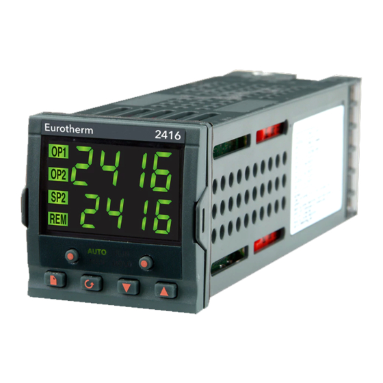
Installation 1 Chapter 1 INSTALLATION The 2416 controller is a versatile, high stability temperature or process controller, with self and adaptive tuning, in 1/16 DIN size (48 x 48mm). It has a modular hardware construction, which accepts up to three plug-in output modules and one communications module, to satisfy a wide range of control requirements. -
Page 6: Mechanical Installation
AUTO HOLD IP65, NEMA 4X sealing gasket Figure 1-2 Outline dimensions The electronic assembly of the controller plugs into a rigid plastic sleeve, which in turn fits into the standard DIN size panel cut-out shown in Figure 1-3. 2416 Controller... -
Page 7: Panel Cut-Out And Recommended Minimum Spacing Of Controllers
If required, the controller can be unplugged from its sleeve by easing the latching ears outwards and pulling it forward out of the sleeve. When plugging the controller back into its sleeve, ensure that the latching ears click into place in order to secure the IP65 sealing. 2416 Controller... -
Page 8: Electrical Installation
Pt100 − V− − Figure 1-4 Rear terminal layout *The ground connection is provided as a return for internal EMC filters. It is not required for safety purposes, but must be connected in order to satisfy EMC requirements. 2416 Controller... -
Page 9: Fixed Connections
The diagrams below show the connections for the various types of input. The input will have been configured in accordance with the ordering code. Resistance mA input Volts or mV inputs Thermocouple thermometer 2.49Ω current sense resistor Fig 1-5 Sensor input connections 2416 Controller... -
Page 10: Plug-In Module Connections
Alarm output Program event output PDS mode 1*, which provides logic heating using a Eurotherm TE10S solid state relay with feedback of a load failure alarm. PDSIO mode 2*, which provides logic heating using a Eurotherm TE10S solid state relay, with feedback of the load current reading and two alarms: solid state relay failure and heater circuit failure. -
Page 11: Communications Module
EIA-232 serial − − − Common communications 4-wire EIA-485 serial − A′ B′ Common communications (Tx+) (Rx+) (Tx−) (Rx−) PDSIO Setpoint − − − − Signal Common retransmission PDSIO remote setpoint input Signal Common Table 1-2 Communications connections 2416 Controller... -
Page 12: Wiring Of 2-Wire Eia-485 Serial Communications Link
Local diagram. This diagram also shows the use of a Eurotherm Earth KD485 converter to connect the EIA-485 link into a standard EIA-232 computer port. -
Page 13: Typical Wiring Diagram
Cooling solenoid valve Thermocouple Fig 1-7 Typical wiring diagram, Model 2416 Controller Safety requirements for permanently connected equipment state: A switch or circuit breaker shall be included in the building installation • It shall be in close proximity to the equipment and within easy reach of the operator •... -
Page 14: Logic Drive Fan Out
3S2P 3S3P 1S2P 6S1P Triple 12V@9 3S3P 2S1P 2S1P 2S1P 4S1P logic TC1027 TE200S TC2000 RS3D Standard Multi- Logic V Logic Logic Logic drive Logic 2S3P 1S2P 6S1P 3S3P 3S3P 3S1P 4S2P Triple 4S1P 2S1P 2S1P logic 1-10 2416 Controller... -
Page 15: Otorised Valve Connections
The convention is to configure Output 1 as the RAISE output and Output 2 as the LOWER output. The controller does not require a position feedback potentiometer. Motor supply Line Neutral RAISE Motorised Ground valve LOWER Comms − − RTD/ Pt100 Fig 1-8 Motorised valve connections 2416 Controller 1-11... - Page 16 Installation Installation and Operation Handbook 1-12 2416 Controller...
-
Page 17: Chapter 2 Operation
2 Chapter 2 OPERATION This chapter has nine topics: • FRONT PANEL LAYOUT • BASIC OPERATION • OPERATING MODES • AUTOMATIC MODE • MANUAL MODE • PARAMETERS AND HOW TO ACCESS THEM • NAVIGATION DIAGRAM • PARAMETER TABLES • ALARM MESSAGES 2416 Controller... -
Page 18: Front Panel Layout
Remote setpoint active (flashes for comms) Program running Auto mode active AUTO Run/Hold button HOLD Auto/Man button (Press & hold to reset) Manual mode active Program in Hold Page Scroll Down Button Button Button Button Figure 2-1 Front panel layout 2416 Controller... - Page 19 Scroll button Press to select a new parameter in a list. Down button Press to decrease a value in the lower readout. Up button Press to increase a value in lower readout. Figure 2-2 Controller buttons and indicators 2416 Controller...
-
Page 20: Basic Operation
If the controller detects an alarm condition, it flashes an alarm message in the Home display. For a list of all the alarm messages, their meaning and what to do about them, see Alarms at the end of this chapter. 2416 Controller... -
Page 21: Operating Modes
Two other modes are also available: • Remote Setpoint mode in which the setpoint is generated from an external source. In this mode the REM light will be on. • Programmer mode which is explained in Chapter 5, Programmer Operation. 2416 Controller... -
Page 22: Automatic Mode
Output Power display may access further parameters. These may be in this scroll list if the ‘Promote’ feature has been used (see Chapter 3, Edit Level). When you reach the end of this scroll list, pressing will return you to the Home display. 2416 Controller... -
Page 23: Manual Mode
Output Power display may access further parameters. Other parameters may be in this scroll list if the ‘Promote’ feature has been used (see Chapter 3, Edit Level). When you reach the end of this scroll list, pressing will return you to the Home display. 2416 Controller... -
Page 24: Parameters And How To Access Them
When you reach the end of the list, you will return to the list header. From within a list you can return to the list header at any time can by pressing . To step to the next list header, press once again. 2416 Controller... -
Page 25: Parameter Names
. During adjustment, single presses change the value by one digit. Keeping the button pressed speeds up the rate of change. Two seconds after releasing either button, the display blinks to show that the controller has accepted the new value. 2416 Controller... -
Page 26: Navigation Diagram (Part A)
Auto Auto PrG.t 35.0 Lb t rEL.2 rEL.C 1.00 1.00 FASt rAtE diAG FF.Pb SEG.n out.n SEG.n FF.tr ti.2 SYnc tYPE tYPE FF.dv td.2 dwEl 100.0 50.0 SEG.d tYPE dwEl Figure 2-6a Navigation diagram (Part A) 2-10 2416 Controller... - Page 27 4. Absolute setpoint limits are set in configuration, see Chapter 6. SP2.H The shaded boxes are normally hidden in Operator level. To 100.0 see all the available parameters you must select Full level. See Chapter 3, Access Levels. SPrr Figure 2-6b Navigation diagram (Part B) 2416 Controller 2-11...
-
Page 28: Parameter Tables
Event output states (OFF / on) (not 8-segment programmer) SYnc Not operational in 2416. Set to no. SEG.d * Flash active segment type in the lower readout of the home display (no / YES) Program edit list − Present only in setpoint programming controllers ProG PrG.n... - Page 29 ‘dwEl’ time / time to target for a ‘rmP.t’ segment PrG.n cALLed ProGram number cYc.n No. of cycles of cALLed program outn Event output: OFF/on (not 8-segment programmer) Not operational in 2416. Set to no. SYnc End.t End of prog − dwEl, RSEt, S OP Name Description Name Description...
- Page 30 Adaptive tune trigger level in display units. Range = 1 to 9999 mp.t Minimum ON time of output pulse Automatic Droop Compensation U.br Not available in 2416 (PD control only) PID list Setpoint list G.SP If Gain Scheduling has been...
- Page 31 Configuration password ConF Output Rate Limit (% per sec) OPrr Forced output level (%) Heat cycle time (0.2S to 999.9S) CYC.H Heat hysteresis (display units) hYS.H Heat output min. on-time (secs) ont.H Auto (0.05S), or 0.1 - 999.9S 2416 Controller 2-15...
-
Page 32: Alarms
These warn that there is a problem with the process which the controller is trying to control. Alarm Alarm What it means What it means Display Display PV Full Scale Low alarm Not available in 2416 _FSL* _FL2* PV Full Scale High alarm Not available in 2416 _FSH* _FH2* PV Deviation Band alarm... -
Page 33: Diagnostic Alarms
Ld.F Load failure This is an alarm generated by feedback from a Eurotherm TE10S solid state relay (SSR) Indication that there is a operating in PDSIO mode 1 - see Chapter 1, fault in the heating circuit or the solid state relay. - Page 34 Acknowledge by pressing ‘page’ key two hours and ‘scroll’ key together P.br Potentiometer break Check that the feedback potentiometer is correctly connected or the pot is not open circuit Table 2-2b Diagnostic alarms 2-18 2416 Controller...
-
Page 35: Chapter 3 Access Levels
(See Edit level at the end of this chapter). Configuration conF This special level allows access to set up the fundamental characteristics of the controller. Figure 3-1 Access levels 2416 Controller... - Page 36 If no button is pressed for ten seconds, you will be returned to the Home display. Alternatively, pressing together takes you immediately back to the Home display. 2416 Controller...
- Page 37 To return to operator level from either ‘FuLL’ or ‘Edit’ level, repeat entry of the password and select ‘OPEr’ on the ‘Goto’ display. In ‘Edit’ level, the controller will automatically return to operator level if no button is pressed for 45 seconds. 2416 Controller...
-
Page 38: Edit Level
(promoted) into the Home display list. (The parameter will also be accessible, as normal, from the standard lists.) A maximum of twelve parameters can be promoted. Promoted parameters are automatically ‘alterable’. Please note, in the ‘PrOG List’, the parameters from segment number (SEG.n) onwards cannot be promoted. 2416 Controller... -
Page 39: Chapter 4 Tuning
Relative cool Only present if cooling has been configured and a module is fitted. Sets the cooling proportional band, which equals the Pb gain value divided by the rEL value. Table 4-1 Tuning parameters 2416 Controller... -
Page 40: Automatic Tuning
Tuning Installation and Operation Handbook AUTOMATIC TUNING Two automatic tuning procedures are provided in the 2416: • A one-shot tuner which automatically sets up the initial values of the parameters listed in Table 4-1 on the previous page. • Adaptive tuning which continuously monitors the error from setpoint and modifies the PID values if necessary. -
Page 41: Typical Automatic Tuning Cycle
Adaptive tune should not be used: 1. Where the process is subjected to regular external disturbances that could mislead the adaptive tuner. 2. On highly interactive multiloop applications. However, moderately interactive loops, such as multi-zone extruders, should not give a problem. 2416 Controller... -
Page 42: Manual Tuning
5. Set the Pb, tiand td parameter values according to the calculations given in Table 4-2. Type of control Proportional Integral time ‘ti’ Derivative time band ‘Pb’ ‘td’ Proportional only P + I control 2.2xB 0.8xT P + I + D control 1.7xB 0.5xT 0.12xT Table 4-2 Tuning values 2416 Controller... -
Page 43: Setting The Cutback Values
In example (a) increase ‘Lcb’ by the overshoot value. In example (b) reduce ‘Lcb’ by the undershoot value. Example (a) Temperature Setpoint Overshoot Example (b) Temperature Setpoint Undershoot Time Where the temperature approaches setpoint from above, you can set ‘Hcb’ in a similar manner. 2416 Controller... -
Page 44: Integral Action And Manual Reset
The display shows tU.Er - Tune Error. This alarm could occur if: 1. The process to be tuned has a very slow response time 2. The sensor has failed or is incorrectly aligned 3. The loop is broken or not responding correctly 2416 Controller... -
Page 45: Motorised Valve Control
Installation and Operation Handbook Tuning MOTORISED VALVE CONTROL The 2416 can be configured for motorised valve control as an alternative to the standard PID control algorithm. This algorithm is designed specifically for positioning motorised valves. These are ordered, pre-configured, as Model numbers: •... -
Page 46: Commissioning The Motorised Valve Controller
If the backlash is sufficient to cause a control problem, then the backlash time needs to be determined and then entered into the parameter, ‘bac.t’. The above two values are not part of the automatic tuning procedure and must be entered manually. 2416 Controller... -
Page 47: Gain Scheduling
The 2416 has two sets of PID values. You can select the active set from either a parameter in the PID list, or you can transfer automatically in gain scheduling mode. The transfer is bumpless and will not disturb the process being controlled. - Page 48 Tuning Installation and Operation Handbook 4-10 2416 Controller...
-
Page 49: Chapter 5 Programmer Operation
Programmer Operation 5 Chapter 5 PROGRAMMER OPERATION This chapter deals with the setpoint programming option. All 2416 instruments have a basic 8-segment programmer built-in as standard. This facility must be enabled by the user, as explained in the section, Configuring the Programmer. - Page 50 WHAT IS SETPOINT PROGRAMMING? Many applications need to vary temperature, or process value, with time. Such applications need a controller which varies a setpoint as a function of time. All 2416 programmer models will do this. The setpoint is varied by using a setpoint program. Within each 2416 controller there is a software module, called the programmer, which stores one, or more, such programs and drives the setpoint according to the selected program.
- Page 51 (see the final topic in this chapter). When a program ends, the programmer is put into either, a continuous Dwell state with all outputs staying unchanged, or the Reset state. Table 5-1 Segment Types 2416 Controller...
- Page 52 Holdback will also occur if the PDSIO output is open circuit. This can be disabled in configuration by selecting the PdS output as SP.nH - ‘setpoint retransmission without holdback’ The program is complete. RUN light flashes Table 5-2 Program States 2416 Controller...
- Page 53 List Press Program number This display will only appear on controllers that can hold more than one program (Models 2416/P4 & 2416/V4). Use to select the required program number, from 1 to 4. Press Status selection to select: •...
- Page 54 ‘OFF’ − Disables Holdback − therefore no action is taken. ‘Lo’ − Deviation Low Holdback holds the program back when the process variable deviates below the setpoint by more than the holdback value. 2416 Controller...
- Page 55 Servo to new PV level Time Time Ramp Dwell Segment Ramp Segment Segment Figure 5-2 Continue after a power fail Figure 5-3 Ramp back after a power fail If ‘rSEt’ is selected, then when power is restored the program terminates. 2416 Controller...
- Page 56 One stored program • Four stored programs • Press Holdback Strategy HbAc to select: Holdback type to be set in each segment • Holdback type to be set for the whole • ProG program Press Continued on the next page. 2416 Controller...
- Page 57 Event outputs disabled • Event outputs enabled • Note: The term Sync appears on 2416 but is not operational and should be set to no. It appears in order to maintain software sync consistency with 2408 and 2404 controllers. Press...
- Page 58 [Only appears when Holdback has been selected for the whole program.] to select: band • Holdback disabled • Deviation Low Holdback • Deviation High Holdback. • bAnd Deviation Band Holdback Press Holdback value Hb V to set a value. Press (Continued on the next page.) 5-10 2416 Controller...
- Page 59 1 to 16. The parameters that follow ‘SEG.n’ set up the characteristics of the individually-selected segment number. By defining the characteristics of each segment of the program, you define the whole program. Press Continued on the next page. 2416 Controller 5-11...
- Page 60 : Holdback disabled • Deviation Low Holdback • Deviation High Holdback • bAnd Deviation Band Holdback Press Target setpoint Target setpoint for ‘rmP.r’, ‘rmP.t’ or ‘StEP’ segments. Set the target setpoint using Press Continued on the next page. 5-12 2416 Controller...
- Page 61 Press Number of cycles of the called program Only appears for ‘cALL’ segments. cyc.n (4-program controllers only) Set the number of cycles of the cALLed program from 1 to 999, using Press Continued on the next page. 2416 Controller 5-13...
- Page 62 . Pressing will step through all the remaining event outputs. In practice, the 2416 has a maximum of three physical outputs, although more than one event can be combined onto a single physical output. See Chapter 6, Configuration.
-
Page 63: Chapter 6 Configuration
Configuration is protected by a password and should only be carried out by a qualified person, authorised to do so. Incorrect configuration could result in damage to the process being controlled and/or personal injury. It is the responsibility of the person commissioning the process to ensure that the configuration is correct. 2416 Controller... -
Page 64: Selecting Configuration Level
‘locked’ then pressing at this point Conf will take you to the ‘Exit’ display with ‘no’ in the lower readout. Simply press to return to the ‘ConF’ display.) You will obtain the first display of configuration. 2416 Controller... -
Page 65: Selecting A Configuration Parameter
To leave the Configuration level and return to Operator level Press display appears. Alternatively, pressing together will take you directly to the ‘Exit’ display. Exit to select ‘YES’. After a two-second delay, the display will blank then revert to the Home display in Operator level. 2416 Controller... -
Page 66: Navigation Diagram (Part A)
1200 to.PV nonE inp.H rmP.U Ltch dtYP 50.0 PSEc FuLL VaL.L bLoc SYnc dELY nonE diSA VaL.H 100.0 diSA Ltch PwrF bLoc Fwd.t nonE Pd.tr Sbr.t Ltch Sb.OP bLoc nonE Fig 6.1a Navigation Diagram (Part A) GSch 2416 Controller... - Page 67 ‘iP-ConF’ has ‘inpt’ = ‘mV.C’, or ‘mA.C’, or ‘V.C’. The navigation diagram shows typical parameters, but is dependant upon the exact configuration of the instrument. The following sheets show the full list of parameters. Fig 6.1b Navigation Diagram (Part B) 2416 Controller...
-
Page 68: Configuration Parameter Tables
Value set in ‘FOP’ of ‘op-List’ in Operator Level BCD input function Not used nonE Only functional in Models 2408 ProG none & 2404. Set ‘ ’ to ‘ Select setpoint number Gain Schedule Enable Disabled Gsch Enabled 2416 Controller... - Page 69 If a decimal point was configured, negative display and setpoint ranges were limited to -99.9 in previous software versions. The range has been increased to -199.9 by combining the negative sign with the figure one. This allows Setpoints, Process Variables, Alarm Setpoints and Programmers to be set to -199.9. 2416 Controller...
- Page 70 Linear Input Scaling − The next four parameters only appear if a linear input is chosen. inP.L Input value low Displayed Value inP.H Input value high VAL.H VAL.L Display reading low VAL.H Display reading high VAL.L Electrical Input inP.L inP.H 2416 Controller...
- Page 71 Alarm 2 Type see Table A Load Current low Ltch Latching no/YES/Evnt/mAn Load Current high bLoc Blocking no/YES Not usable on 2416 Alarm 3 Type Not usable on 2416 see Table A Working Output low Ltch Latching no/YES/Evnt/mAn Working Output high...
- Page 72 Programmable event Disabled outputs Enabled Synchronisation of programs Disabled SYNC of several programmers Enabled Not usable in Model 2416 Select ‘no’ Name Description Values Meaning Comms 1 module config Identity of the module EIA-232, or 2-wire EIA-485, or 4-wire installed...
- Page 73 Name Description Values Meaning For ‘id’ = ‘cms’ use this parameter table: Func Function Modbus protocol EI.bi Eurotherm Bisynch protocol bAud 1200, 2400, 4800, 9600, 19.20(19,200) Baud Rate dELy Delay - quiet period, required No delay by some comms adaptors Delay active - 10mS The following parameters only appear if the function chosen is Modbus protocol.
- Page 74 Normal (output energises SEnS when TRUE, e.g program (Only if ‘Func’ = ‘dIG’) events) Inverted (output de- energises when TRUE, e.g. alarms) When ‘SEnS’ appears, then further parameters are available. See the table on the next page. 6-12 2416 Controller...
- Page 75 * PDS module connection or YES / no remote input open circuit iP1.F * Input 1 fail (not usable on 2416) YES/no nw.AL * New Alarm has occurred YES / no * End of setpoint rate limit, or end...
- Page 76 1 in 3 in 8 Note: 1. Custom Linearisation is only available when ‘ip- ConF list has ‘inpt’ set to ‘mV.C’, or ‘mA.C’, or ‘V.C’ Custom curves must be continuously increasing or decreasing in value and input. 6-14 2416 Controller...
- Page 77 High impedance: 1.0 Volt cal’n point HI 1.0 Restore factory calibration FACt Start calibration Waiting to calibrate PV point Start calibration Select ‘YES’ with Wait for calibration to Busy calibrating buSy PV input calibration completed complete. donE Calibration failed FAIL 2416 Controller 6-15...
- Page 78 Calculated offset, in display units. Name Description Values Meaning PASS Password configuration Full or Edit level password ACC.P Configuration level cnF.P password Note:- When passwords are changed please make a note of the new numbers Exit no/YES Exit configuration 6-16 2416 Controller...
-
Page 79: Chapter 7 User Calibration
Match the calibration of the controller to that of a particular transducer or sensor input. Calibrate the controller to suit the characteristics of a particular installation. Remove long term drift in the factory set calibration. User calibration works by introducing a single point, or two-point, offset onto the factory set calibration. 2416 Controller... -
Page 80: User Calibration Enable
‘CAL-Conf’ list. ×2 Press until you reach ‘UCAL’. User Calibration Enable UCAL to select: • YES: Calibration enable • Calibration disabled together to go to the Exit display. Press Exit configuration to select ‘YES’ to return to Operator level. 2416 Controller... -
Page 81: Offset Calibration
‘CAL’ display. Calibration type • FACt: Factory Calibration • User Calibration USEr: FACt to select ‘FACt’. Selecting ‘FACt’ reinstates the factory calibration and allows the application of a single fixed offset. Press continued on the next page 2416 Controller... - Page 82 Li.1 IP1 Linearised Value PV.SL Not available in Model 2416 If you do not want to look at these parameters, then press and this returns you to the ‘iP-LiSt’ header. To protect the calibration against unauthorised adjustment, return to Operator level and make sure that the calibration parameters are hidden.
-
Page 83: Two-Point Calibration
‘CAL’ display. Calibration type • FACt: Factory Calibration • USEr: User Calibration to select ‘USEr’. USEr Selecting ‘USEr’ enables two-point calibration. [If two-point calibration is unsatisfactory, select ‘FACt’ to return to the factory set calibration.] Press 2416 Controller... - Page 84 • Input 1 (PV1) calibration high-point selected ip2.L: • Not available in Model 2416 ip2.H: • Not available in Model 2416 to select the parameter for the Low Calibration point of Input 1, ‘ip1.L’ & follow route shown on this page.
- Page 85 Press to return to the ‘ip-List’ header. To protect the calibration against unauthorised adjustment return to Operator level and make sure that the calibration parameters are hidden. Parameters are hidden using the ‘Edit’ facility described in Chapter 3. 2416 Controller...
-
Page 86: Calibration Points And Calibration Offsets
Offset Low for Input 1 Calculated offset, in display units. OF1.H Offset High for Input 1 Calculated offset, in display units. Note: The value of each of the parameters in the above table may also be altered by using buttons. 2416 Controller... -
Page 87: Chapter 8 Load Current Monitoring And Diagnostics
DIAGNOSTICS Current flowing in a system of electrical heating elements (the ‘Load’) can be displayed on the controller by using a Eurotherm TE10 SSR fitted with intelligent current transformer, PDCTX, or an SSR or contactor with an external PDCTX. Load current monitoring and diagnostics may be used with any time proportioned output,... -
Page 88: Example Wiring Diagram (For Mode 1 & 2 Operation)
1. Eurotherm SSR type TE10/PDS2 OR 2. Eurotherm intelligent current transformer type PD/CTX + contactor or zero voltage switching SSR 2416 controller configured for PDS mode 2 option using logic output. This module must be fitted in module position 1. (order code M2). Controller... -
Page 89: Operation
SSR RMS On State Current This is the default state when high or low current alarms are configured. The load current displayed is the steady state true rms current measured during the ON period. The minimum on times are:- Mode 2 0.1second 2416 Controller... -
Page 90: How Heater Alarms Are Displayed
AL LiSt, see ‘SHORT CIRCUIT SSR ALARM AND HEATER FAIL ALARM’ Htr.F Heater Fail No current is being drawn while the controller output demand signal is on SSr.F SSR Fail The load is continuously on while the controller output demand signal is off 2416 Controller... -
Page 91: To Set The Alarm Trip Levels
Any plug in module can be used for alarms provided they are not already being used for another purpose , such as control. Any one or more alarms can be attached to an output, which will operate when an alarm occurs. Contacts are rated at 2A 264Vac for operating external beacons or audible devices. 2416 Controller... -
Page 92: To Configure Pds Load Current Diagnostics
VAL.L To set the minimum Press PID signal to 0% to show 0.0 This is the upper Press to show PID demand level VAL.H VAL.H) 100.0 To set the maximum Press PID signal to 100% to show 100.0 2416 Controller... - Page 93 Press to show output power OUT.H OUT.H To set the max Press output power to 100 to show 100.0 This sets the output Press to show SEnS signal to normal for SEnS heating control Press to show nor 2416 Controller...
-
Page 94: To Configure Low And High Current Trip Alarms
AL2 (alarm 2) alarm type has been appears accepted To make alarm 2 = Press High Current to show HCr Note:- The above alarms are known as SOFT ALARMS because they are indication only. 2416 Controller... -
Page 95: To Attach Soft Alarms To A Relay Output
Press no means the to select YES or output will not activate Repeat the above step for every alarm to be attached to the output Alarms Connected to a Relay Output Soft Alarms SEnS Output Module 2416 Controller... -
Page 96: 8.10 The Scaling Factor
25 as shown in the table below. Scalar = 100/N Where N = Turns through PDCTX Scalar Scalar Maximum Resolvable Current TE10 Determined by the maximum range of the SSR PDCTX 100A (or 100 ampere turns) Finally Exit configuration level. See Chapter 5 8-10 2416 Controller... -
Page 97: Appendix Aunderstanding The Ordering Code
Ordering Code Appendix A UNDERSTANDING THE ORDERING CODE The 2416 controller has a modular hardware construction, which accepts up to three plug-in Input/Output modules and one communications module, to satisfy a wide range of control requirements. The ordering code is in two parts. The hardware coding and an optional configuration coding. - Page 98 PDSIO mode 1 VP/Four Program. PDSIO mode 2 16-segment Triac Fitted unconfigured PID heating Valve raise output DC control non-isolated Unconfigured Supply voltage 0-20mA heating 85 to 264Vac 4-20mA heating 20 to 29Vac/dc 0-5Vdc heating 1-5Vdc heating 0-10Vdc heating 2416 Controller...
- Page 99 0-10Vdc cooling −1 0 to 20mA PDSIO input −2 4 to 20mA Fitted unconfigured −3 0 to 5V Setpoint input −4 1 to 5V PDSIO output −5 0 to 10V Fitted unconfigured PV retransmission Setpoint retrans Output retrans 2416 Controller...
- Page 100 PDSIO is a proprietary technique developed by Eurotherm for bi-directional transmission of analogue and digital data between instruments. Mode 1: provides logic heating to a Eurotherm TE10S solid state relay with feedback of a general load fault alarm. Mode 2: provides logic heating to a Eurotherm TE10S solid state relay with feedback of load current and two alarms: solid state relay failure and heater circuit failure.
-
Page 101: Appendix Bsafety And Emc Information
-20 C to +70 SERVICE AND REPAIR This controller has no user serviceable parts. Contact your nearest Eurotherm agent for repair. Caution: Charged capacitors Before removing an instrument from its sleeve, disconnect the supply and wait at least two minutes to allow capacitors to discharge. - Page 102 For example in the UK use the latest version of the IEE wiring regulations, (BS7671). In the USA use NEC Class 1 wiring methods. 2416 Controller...
- Page 103 2. These are defined as follows:- Installation Category II The rated impulse voltage for equipment on nominal 230V supply is 2500V. Pollution Degree 2 Normally only non conductive pollution occurs. Occasionally, however, a temporary conductivity caused by condensation shall be expected. 2416 Controller...
- Page 104 To ensure compliance with the European EMC directive certain installation precautions are necessary as follows: • For general guidance refer to Eurotherm EMC Installation Guide, HA025464. • When using relay or triac outputs it may be necessary to fit a filter suitable for suppressing the emissions.
-
Page 105: Appendix Ctechnical Specification
One shot (automatic tune of PID and overshoot inhibition parameters) and continuous adaptive tuning. Automatic calculation of manual reset value when using PD control. Auto/manual control Bumpless transfer or forced manual output Setpoint rate limit 0.00 to 999.9 display units per second, minutes or hour 2416 Controller... - Page 106 Meets EN61010, installation category II (voltage transients must not exceed 2.5kV), pollution degree 2 Atmospheres Not suitable for use above 2000m or in explosive or corrosive atmospheres. Electrically conductive pollution must be excluded from the cabinet in which this controller is mounted 2416 Controller...
-
Page 107: Appendix D Rohs Statement
Indicates that this toxic or hazardous substance contained in at least one of the homogeneous materials used for this part is above the limit requirement in SJ/T11363-2006. Approval Name: Position: Signature: Date: Martin Greenhalgh Quality Manager IA029470U470 (CN23172) Issue 1 Feb 07 2416 Controller... - Page 108 RoHS Installation and Operation Handbook 2416 Controller...
- Page 110 The specifications in this document may therefore be changed without notice. The information in this document is given in good faith, but is intended for guidance only. Eurotherm Limited will accept no responsibility for any losses arising from errors in this document.
Need help?
Do you have a question about the 2416 and is the answer not in the manual?
Questions and answers