Table of Contents
Advertisement
Quick Links
Download this manual
See also:
Manual
Advertisement
Table of Contents

Related Manuals for Eurotherm 3508


Summary of Contents for Eurotherm 3508
- Page 1 PROCESS CONTROLLERS Engineering handbook 2 rue René Laennec 51500 Taissy France E-mail:hvssystem@hvssystem.com Fax: 03 26 85 19 08, Tel : 03 26 82 49 29 Site web : www.hvssystem.com...
-
Page 2: Table Of Contents
3508 and 3504 Process Controllers CHAPTER 1 INSTALLATION AND OPERATION ........10 WHAT INSTRUMENT DO I HAVE?..................... 10 1.1.1 Contents of Package ........................10 3504 AND 3508 ORDERING CODE ....................11 1.2.1 Input and Output Modules....................... 11 HOW TO INSTALL THE CONTROLLER..................12 1.3.1 Dimensions ............................ - Page 3 Engineering Handbook 3500 series Controllers CHAPTER 2 ACCESS TO FURTHER PARAMETERS ......44 2.1.1 Level 3............................. 44 2.1.2 Configuration Level......................... 44 2.1.3 To Select Different Levels of Access ....................45 ACCESS PARAMETER LIST ......................46 CHAPTER 3 FUNCTION BLOCKS ............48 TO ACCESS A FUNCTION BLOCK....................
- Page 4 3500 Series Controllers Engineering Handbook CHAPTER 8 AA RELAY OUTPUT ............80 TO SELECT AA RELAY LIST .....................80 AA RELAY PARAMETERS......................80 8.2.1 Example: To Wire the AA Relay to an Alarm................81 8.2.2 Relay Output Scaling........................81 CHAPTER 9 MODULE CONFIGURATION ..........82 TO FIT A NEW MODULE......................83 MODULE IDENTIFICATION ......................84 MODULE TYPES..........................84...
- Page 5 Engineering Handbook 3500 series Controllers 13.3 BROADCAST MASTER COMMUNICATIONS ..............113 13.3.1 3500 Broadcast Master........................113 13.3.2 Wiring Connections - Broadcast Communications................ 114 13.4 DIGITAL COMMUNICATIONS PARAMETERS ..............115 13.4.1 Communications Identity....................... 116 13.4.2 Communication Address........................ 116 13.4.3 Baud Rate ............................116 13.4.4 Parity .............................
- Page 6 3500 Series Controllers Engineering Handbook INPUT MONITOR ..................136 16.1.1 Maximum Detect ........................... 136 16.1.2 Minimum Detect..........................136 16.1.3 Time Above Threshold........................136 16.2 INPUT MONITOR PARAMETERS..................137 CHAPTER 17 LOGIC AND MATHS OPERATORS......... 138 17.1 LOGIC OPERATORS ........................ 138 17.1.1 Logic 8............................
- Page 7 Engineering Handbook 3500 series Controllers 20.6.3 Manual Tracking .........................167 20.6.4 Rate Limit............................167 20.6.5 Setpoint Parameters ........................167 20.7 OUTPUT FUNCTION BLOCK....................169 20.7.1 Power Feed Forward Enable......................172 20.7.2 Output Limits..........................173 20.7.3 Effect of Control Action, Hysteresis and Deadband..............174 CHAPTER 21 SETPOINT PROGRAMMER .......... 176 21.1 PROGRAMMER OPERATING STATES................177 21.1.1...
- Page 8 3500 Series Controllers Engineering Handbook 25.3 CALIBRATION PARAMETERS....................205 CHAPTER 26 CONFIGURATION USING ITOOLS ....... 208 26.1 FEATURES..........................208 26.2 ON-LINE/OFF-LINE EDITING....................208 26.3 CONNECTING A PC TO THE CONTROLLER ..............209 26.4 PARAMETER SET UP......................210 26.5 DEVICE PANEL ........................211 26.6 USER PAGES EDITOR......................212 26.6.1 To Create a User Page .........................212 26.6.2...
- Page 9 Further chapters describe configuration of the controller and operation in level 3. The order of chapters is the same order as the subject headers presented in the controller. Related handbooks, all of which can be downloaded from www.eurotherm.co.uk, may be useful for further information EMC booklet Part No.
- Page 10 3500 Series Controllers Engineering Handbook Part No HA027988 Issue 3.0 Aug-04 2 rue René Laennec 51500 Taissy France E-mail:hvssystem@hvssystem.com Fax: 03 26 85 19 08, Tel : 03 26 82 49 29 Site web : www.hvssystem.com...
-
Page 11: Chapter 1 Installation And Operation
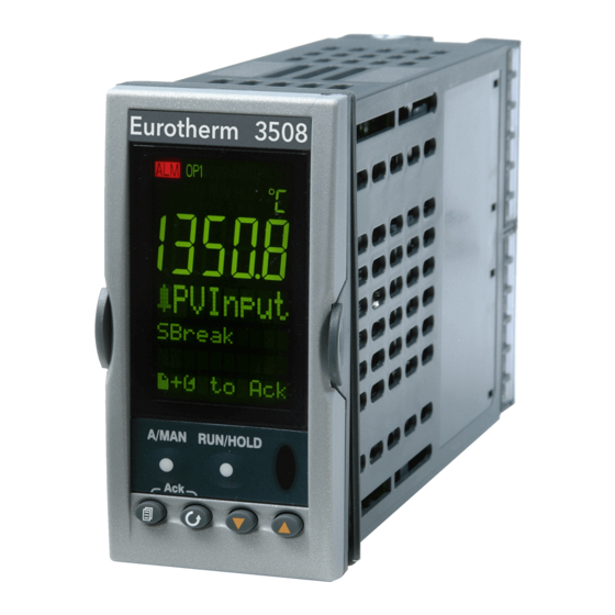
Thank you for choosing this Controller. The 3508 controller is supplied in the standard 1/8 DIN size (48 x 96mm front panel). The 3504 controller is supplied in the standard ¼ DIN size (96 x 96mm front panel). They are intended for permanent installation, for indoor use only, in an electrical panel which encloses the rear housing, terminals and wiring on the back. -
Page 12: And 3508 Ordering Code
Config Tools Product Language Manuals Language Warranty Cal Cert Custom Label H Comms Slot Config Tools Extended Warranty IO Slots 1-3 (3508); 1-6 (3504) Not Fitted None WL005 Extended 5 year None fitted 232 Modbus Standard Change over relay iTools... -
Page 13: How To Install The Controller
Engineering Handbook 3500 series Controllers How to Install the Controller This instrument is intended for permanent installation, for indoor use only, and to be enclosed in an electrical panel. Select a location where minimum vibrations are present and the ambient temperature is within 0 and 50 (32 and 122 The instrument can be mounted on a panel up to 15mm thick. -
Page 14: To Install The Controller
Insert the controller through the cut- out. 92 mm - Spring the panel retaining clips into 0.0 + 0.8 3504 3508 place. Secure the controller in position by holding it level and pushing both 3.62 in - retaining clips forward. 0.00, +0.03... -
Page 15: Electrical Connections
Engineering Handbook 3500 series Controllers Electrical Connections 3508 Live Power Neutral Supply Ground Logic I/O A Digital Logic I/O B Inputs/outputs Logic I/O Com Fixed Relay (form C) PV input T/C RTD Polarising Keys* One per module 3504 Live Neutral... -
Page 16: Standard Connections
3500 Series Controllers Engineering Handbook Standard Connections These are connections which are common to all instruments in the range. 1.5.1 PV Input (Measuring Input) Notes: Do not run input wires together with power cables When shielded cable is used, it should be grounded at one point only Any external components (such as zener barriers, etc) connected between sensor and input terminals may cause errors in measurement due to excessive and/or un-balanced line resistance or possible leakage currents... -
Page 17: Digital I/O
Engineering Handbook 3500 series Controllers 1.5.2 Digital I/O These terminals may be configured as logic inputs, contact inputs or logic outputs in any combination It is possible to have one input and one output on either channel. The Digital IO is not isolated from the PV input 1.5.2.1 Logic Inputs Voltage level logic inputs, 12V, 5-40mA... -
Page 18: Power Supply Connections
3500 Series Controllers Engineering Handbook 1.5.5 Power Supply Connections Before connecting the instrument to the power line, make sure that the line 100 to 240Vac voltage corresponds to the description on the identification label 50/60Hz For supply connections use 16AWG or larger wires rated for at least 75 Use copper conductors only For 24V the polarity is not important It is the Users responsibility to provide an external fuse or circuit breaker. -
Page 19: Plug In I/O Module Connections
Plug in I/O Module Connections Plug in I/O modules can be fitted in three positions in the 3508 and six positions in 3504. The positions are marked Module 1, Module 2, Module 3, Module 4, Module 5, Module 6. With the exception of the Analogue Input module, any other module listed in this section, can be fitted in any of these positions. - Page 20 3500 Series Controllers Engineering Handbook First triac Raise Triac Heating, cooling, and Dual and TT Voltage valve raise, Triac Motorised supply valve lower valve (0.7A, 30 to 264Vac Lower Second triac combined rating) Note 1: Dual relay modules may be used in place of dual triac. Isolated output 240Vac CATII Note 2:- The combined current rating for the two triacs must not...
- Page 21 Engineering Handbook 3500 series Controllers To power an Transmitter external Supply transmitter Transmitter (20mA) Isolated output 240Vac CATII Potentiomet er input +0.5V 100Ω to 15KΩ Isolated output 240Vac CATII Calibration resistor – may be internal or external Transducer Power Transducer Supply 10Vdc power Configurable...
- Page 22 3500 Series Controllers Engineering Handbook I/O Module Typical Order Connections and examples of use usage Code Thermocouple 3-wire RTD Analogue Second or Input third PV input (T/C & RTD) Modules 1, 3 4, & 6 only For 2-wire this is a local link mV (+40mV up +80mV) (mV, V and mVolt...
-
Page 23: Zirconia Probe Construction
Engineering Handbook 3500 series Controllers 1.6.2 Zirconia Probe Construction Outer Electrode Screen Ceramic Insulator Inner Electrode Zirc. mV Hot End Thermocouple Zirconia Sensor Outer metallic shell of the probe 1.6.3 Zirconia Probe Screening Connections The zirconia sensor wires should be screened and connected to the outer shell of the probe if it is situated in an area of high interference. -
Page 24: Digital Communications Connections
Engineering Handbook Digital Communications Connections Digital Communications modules can be fitted in two positions in both 3508 and 3504 controllers. The connections being available on HA to HF and JA to JF depending on the position in which the module is fitted. -
Page 25: Devicenet Wiring
Engineering Handbook 3500 series Controllers 1.7.2 Devicenet Wiring A description of DeviceNet is given in the DeviceNet Communications Handbook Part No HA027506 which can be downloaded from www.eurotherm.co.uk. Terminal Color Description Reference Label Chip DeviceNet network power positive terminal. Connect the red wire of the DeviceNet cable here. -
Page 26: Profibus
3500 Series Controllers Engineering Handbook 1.7.4 Profibus A description of ProfiBus is given in the Profibus Communications Handbook Part No HA026290 which can be downloaded from www.eurotherm.co.uk. 1.7.5 Example Profibus Wiring Connections ‘daisy chained’ to other instruments Shield VP (+5V) -
Page 27: I/O Expander (Or Additional Digital Input)
Engineering Handbook 3500 series Controllers 1.7.7 I/O Expander (or Additional Digital Input) An I/O expander (Model No 2000IO) can be used with 3500 series controllers to allow the number of I/O points to be increased by up to a further 20 digital inputs and 20 digital outputs. Data transfer is performed serially via an IO Expander module which is fitted in digital communications slot J. -
Page 28: Example Wiring Diagram
Please refer to the EMC Electromagnetic Compatibility Handbook Part No. HA025464 for details of good wiring practice. This can be downloaded from www.eurotherm.co.uk. 1.7.9 Snubbers Snubbers are used to prolong the life of relay contacts and to reduce interference when switching inductive devices such as contactors or solenoid valves. -
Page 29: Getting Started
Each time button is pressed a new parameter will be presented This is illustrated by the following example:- (The views shown are taken from the 3508 controller but the same information is included in the 3504). ☺ Backscroll – to scroll back through parameters press and hold... - Page 30 3500 Series Controllers Engineering Handbook Example Do This Display Additional Notes The first parameter to be configured is ‘Units’. It From the Start view press resides in the ‘PV Input List’ because it is associated with the process variable. Press When the required choice is selected a brief blink of change the ‘Units’...
-
Page 31: Quick Start Parameters
Engineering Handbook 3500 series Controllers 1.9.2 Quick Start Parameters Parameters shown in Bold are defaults. Group Parameter Value Availability PV Input Units C, F, K Always V. mV, A, mA, pH, mmHg, psi, Bar, Used to select the engineering units for mBar, %RH, %, mmWG, inWG, inWW, the PV Ohms, PSIG, %O2, PPM, %CO2, %CP,... - Page 32 The following parameters configure the plug in I/O modules. I/O Modules can be fitted in any available slot in the instrument (6 slots in 3504, 3 slots in 3508). The controller automatically displays parameters applicable to the module fitted - if no module is fitted in a slot then it does not appear in the list.
- Page 33 Engineering Handbook 3500 series Controllers Module type Parameter Value Availability Range Type Thermocouple: J, K, L, R, B, N, T, S, PL2, C. Not shown if analogue IP function not used RTD: Pt100 Linear: 0-50mV, 0-5V, 1-5V, 0-10V, 2-10V, 0- 20mA, 4-20mA Display High 100.0...
-
Page 34: To Re-Enter Quick Start Mode
3500 Series Controllers Engineering Handbook 1.10 To Re-enter Quick Start Mode If you have exited from Quick Start mode (by selecting ‘Yes’ to the ‘Finished’ parameter) and you need to make further changes, the Quick start mode can be entered again at any time. The action which takes place depends on one of two previous conditions as follows:- 1.10.1 Power up After a Quick Start Configuration... -
Page 35: Normal Operation
Flashes when infra red communications active In general throughout this handbook instrument views will use the 3504. The displayed information is similar for the 3508 but in some cases is shortened due to display limitations. Part No HA027988 Issue 3.0 Aug-04 2 rue René... -
Page 36: The Operator Buttons
3500 Series Controllers Engineering Handbook 1.12 The Operator Buttons Page Scroll Lower Raise A/MAN Manual operation means that the controller output power is adjusted by the user. The input sensor is still connected and reading the PV but the control loop is open. This button can be disabled When pressed, this toggles between automatic and manual operation. -
Page 37: To Set The Required Temperature (Setpoint)
Engineering Handbook 3500 series Controllers 1.13 To Set The Required Temperature (Setpoint) From the HOME display, press button. 3504 View 3508 View Setpoint Value WSP is the current Working SetPoint. When the button is pressed the mnemonic changes to the setpoint source, e.g. -
Page 38: Alarm Indication
3500 Series Controllers Engineering Handbook 1.15 Alarm Indication If an alarm occurs it is indicated as follows:- The red alarm (ALM) beacon in the top left of the display flashes Alarm number is indicated together with the flashing " A default message or a pre-programmed message appears showing the source of the alarm Invitation to acknowledge the new alarm 1.15.1... -
Page 39: Message Centre
The lower section of the HOME display contains an alpha-numeric set of messages. These messages change between different controller types and operating modes and are grouped in summary pages. The 3504 contains more information than the 3508, and generally the parameter descriptions are longer due to the larger display. -
Page 40: How To Edit Parameters
3500 Series Controllers Engineering Handbook 1.16.2 How to Edit Parameters In the above summary pages, press to scroll to further parameters (where applicable). to change the value of the parameter selected. Press Any parameter preceded by v is alterable provided the system is in a safe state to allow the parameter to be changed. -
Page 41: Programmer Summary
Engineering Handbook 3500 series Controllers 1.16.3 Programmer Summary Page Provided it has been ordered and enabled the 3500 series controllers can program the rate of change of setpoint. Up to 50 programs and up to a maximum of 200 segments can be stored and run. Chapter 21 explains setpoint programming in more detail. - Page 42 3500 Series Controllers Engineering Handbook 1.16.3.2 To Select and Run a Program In this example it is assumed that the program to be run has already been entered. Setpoint programming is described in detail in Chapter 21 of the Engineering Handbook. Do This The Display You Should See Additional Notes...
-
Page 43: Alarm Summary
Engineering Handbook 3500 series Controllers 1.16.4 Alarm Summary Page This page shows a summary of all analogue alarms. Press to scroll through the alarms. The diagram illustrates that an alarm is present in the system but that none of the alarms need acknowledgement. A New Alarm occurs when any new alarm becomes active. -
Page 44: Control Summary
3500 Series Controllers Engineering Handbook 1.16.6 Control Summary Page Parameters which define the way a control loop operates can be set in this page. Control parameters are further described in Chapter 20. Press to scroll through a list of parameters. Press to change the value of the selected parameter. -
Page 45: Chapter 2 Access To Further Parameters
Engineering Handbook 3500 series Controllers 2. CHAPTER 2 ACCESS TO FURTHER PARAMETERS Parameters are available under different levels of security defined as Level 1, Level 2, Level 3 and Configuration Level. Level 1 has no security password since it contains a minimal set of parameters generally sufficient to run the process on a daily basis. -
Page 46: To Select Different Levels Of Access
If no button is pressed for about 2 minutes the display returns to the HOME display. This is a view for the 3504, and shows additional parameters in the list. The 3508 shows these parameters one at a time In either controller, press... -
Page 47: Access Parameter List
It requires an IR clip, available from Eurotherm, to link your Instrument to a PC. A/Man Func This enables or disables the front panel A/MAN... - Page 48 3500 Series Controllers Engineering Handbook Part No HA027988 Issue 3.0 Aug-04 2 rue René Laennec 51500 Taissy France E-mail:hvssystem@hvssystem.com Fax: 03 26 85 19 08, Tel : 03 26 82 49 29 Site web : www.hvssystem.com...
-
Page 49: Chapter 3 Function Blocks
Engineering Handbook 3500 series Controllers 3. CHAPTER 3 FUNCTION BLOCKS The controller software is constructed from a number of ‘function blocks’. A function block is a software device which performs a particular duty within the controller. It may be represented as a ‘box’ which takes data in at one side (as inputs), manipulates the data internally (using parameter settings) and ‘outputs’... -
Page 50: To Access A Function Block
3500 Series Controllers Engineering Handbook To Access a Function Block Press the Page button until the name of the function block is shown in the page header. Access List Header Instrument List Header Input List Header Keep pressing to select further list headers The list is continuous Figure 3-2: Parameter List Headings... -
Page 51: To Change The Value Of A Parameter
Engineering Handbook 3500 series Controllers 3.1.3 To Change the Value of a Parameter Press to raise or lower the value of an analogue (numeric) parameter or to change the selection of enumerated parameter options. Any parameter preceded by v is alterable provided the system is in a safe state to allow the parameter to be changed. -
Page 52: Navigation Diagram
3500 Series Controllers Engineering Handbook Navigation Diagram The diagram below shows all the function blocks available in the 3500 series controllers as list headings in configuration level. A function block will not be shown if it has not been enabled or ordered if it is a chargeable option. -
Page 53: Chapter 4 Function Block Wiring
Engineering Handbook 3500 series Controllers 4. CHAPTER 4 FUNCTION BLOCK WIRING Input and output parameters of function blocks are wired together in software to form a particular instrument or function within the instrument. A simplified overview of how these may be interconnected to produce a single control loop is shown below. -
Page 54: Soft Wiring
3500 Series Controllers Engineering Handbook The timer, programmer and alarms blocks may be made to operate on a number of parameters within the controller, and digital communications provides an interface to data collection and control. The controller can be customised to suit a particular process by ‘soft wiring’ between function blocks. The procedure is described in the following sections. -
Page 55: Wiring Through The Operator Interface
Engineering Handbook 3500 series Controllers 4.1.2 Wiring Through the Operator Interface The example shown in the previous section will be used. Select configuration level as described in section 2.1.3. Then:- Do This The Display You Should See Additional Notes This locates the parameter you want to From any display press wire TO locate the page in which the... -
Page 56: To Remove A Wire
3500 Series Controllers Engineering Handbook 4.1.3 To Remove a Wire Do This The Display You Should See Additional Notes Select the wired parameter eg LgcIO PV in the above example, This locates the parameter you want to A/MAN wire TO Press 10. -
Page 57: Wiring A Parameter To Multiple Inputs
Engineering Handbook 3500 series Controllers 4.1.4 Wiring a Parameter to Multiple Inputs You can repeat the procedure given in section 4.1.2. but it is also possible to ‘Copy’ and ‘Paste’ a parameter. In configuration level the RUN/HOLD button becomes a copy function. The following example wires Ch1 Output to both LA and LB PV inputs. -
Page 58: Wiring Floats With Status Information
3500 Series Controllers Engineering Handbook 4.1.6 Wiring Floats with Status Information There is a subset of float values which may be derived from an input which may become faulty for some reason, e.g. sensor break, overrange, etc. These values have been provided with an associated status which is automatically inherited through the wiring. - Page 59 Engineering Handbook 3500 series Controllers The Poly, Lin16, SwitchOver, Mux8, IO.Mod, and IO.PV blocks can be configured to act on bad status in varying ways. The options available are as follows:- 0: Clip Bad The measurement is clipped to the limit it has exceeded and its status is set to ‘BAD’, such that any function block using this measurement can operate its own fallback strategy.
-
Page 60: Edge Wires
3500 Series Controllers Engineering Handbook 4.1.7 Edge Wires If the Loop.Main.AutoMan parameter was wired from a logic input in the conventional manner it would be impossible to put the instrument into manual from the front panel of the instrument. Other parameters need to be controlled by wiring but also need to be able to change under other circumstances, e.g. -
Page 61: Operation Of Booleans And Rounding
Engineering Handbook 3500 series Controllers 4.1.8 Operation of Booleans and Rounding 4.1.8.1 Mixed Type Wiring Parameters of function blocks are one of the following types shown below. Wires which connect one type to another cause a type conversion to occur. The values wired may also be rejected or clipped depending on type and limits. -
Page 62: Chapter 5 Instrument Configuration
3500 Series Controllers Engineering Handbook 5. CHAPTER 5 INSTRUMENT CONFIGURATION WHAT IS INSTRUMENT CONFIGURATION? Instrument configuration allows you to:- Enable controller options Customise the display Read information about the controller Read internal diagnostics To Select Instrument Configuration Select Configuration level as described in Chapter 2. The first view displayed is the header ‘Inst’... -
Page 63: Options Available In The Instrument Configuration List
Engineering Handbook 3500 series Controllers 5.3.1 Options Available in the Instrument Configuration List The following table lists the options which can be enabled in the controller:- List Header: Inst Sub-header: Opt Name Parameter Value Default Access Description Level to select to change AnAlm En Analogue alarms... -
Page 64: Display Formatting
3500 Series Controllers Engineering Handbook UsrVal En1 User values Conf All 8 user values disabled UsrVal En1 All 8 user values enabled ZirconiaEn To enable the Zirconia block disabled Zirconia function Zirconia block enabled block. This is only available if ordered Note:- The left most flag indicates the first instance e.g. - Page 65 Engineering Handbook 3500 series Controllers List Header: Inst Sub-header: Disp Name Parameter Description Value Default Access Level to select to change Units Instrument temperature units as shown Celsius in the top right of the display Fahrenheit Kelvin Home Page Configures which set of parameters are Loop Loop summary Loop...
-
Page 66: Bar Graph (3504 0Nly)
3500 Series Controllers Engineering Handbook 5.4.2 Bar Graph (3504 0nly) The bar graph shown on the left hand side of the display can be wired to any analogue parameter. The example shown in section 26.11.1. shows the bar graph wired to the main PV. Markers can also be placed on the bar graph which can be used to indicate minimum and maximum points. -
Page 67: Instrument Diagnostics
Engineering Handbook 3500 series Controllers Instrument Diagnostics This list provides fault finding diagnostic information as follows:- List Header: Sub-header: Diag Inst Name Parameter Description to select CPU % Free This is the amount of free CPU Time left. It shows the percentage of the tasks ticks that are idle. CPU % Min A benchmark of the lowest reached value of the CPU free percentage. - Page 68 3500 Series Controllers Engineering Handbook Invalid custom linearisation table. One of the custom linearisation tables is invalid. Either it has failed checksum tests or the table downloaded to the instrument is invalid. Unused Unused Unused The Instrument wiring is either invalid or corrupt. Non Vol write to volatile.
-
Page 69: Chapter 6 Process Input
Engineering Handbook 3500 series Controllers 6. CHAPTER 6 PROCESS INPUT The process input list characterizes and ranges the signal from the input sensor. The Process Input parameters provide the following features:- Input Type and Thermocouple (TC) and 3-wire resistance thermometer (RTD) temperature detectors linearisation Volts, mV or mA input through external shunt or voltage divider, available with linear, square root or custom linearisation... - Page 70 3500 Series Controllers Engineering Handbook CJC Type To select the cold junction Internal See description in section 6.2.2. for Internal Conf compensation method further details External SBrk Type Sensor break type Sensor break will be detected when its Conf impedance is greater than a ‘low’ value High Sensor break will be detected when its impedance is greater than a ‘high’...
-
Page 71: Input Types And Ranges
Engineering Handbook 3500 series Controllers Cal State Calibration state Idle Conf Calibration of the PV Input L3 R/O is described in Chapter 25. Status PV Status Normal operation The current status of the Initial startup mode Input in sensor break PV outside operating limits Saturated input Uncalibrated channel... -
Page 72: Cjc Type
3500 Series Controllers Engineering Handbook 6.2.2 CJC Type A thermocouple measures the temperature difference between the measuring junction and the reference junction. The reference junction, therefore, must Measuring either be held at a fixed known temperature or accurate compensation be used junction for any temperature variations of the junction. -
Page 73: Display Units
Engineering Handbook 3500 series Controllers 6.2.3 Display Units None Abs Temp V, mV, A, mA, PH, mmHg, psi, Bar, mBar, %RH, %, mmWG, inWG, inWW, Ohms, PSIG, %O2, PPM, %CO2, %CP, %/sec, RelTemp K(rel), sec, min, hrs, 6.2.4 Sensor Break Value The controller continuously monitors the impedance of a transducer or sensor connected to any analogue input (including plug in modules). -
Page 74: Pv Offset
3500 Series Controllers Engineering Handbook 6.2.6 PV Offset All ranges of the controller have been calibrated against traceable reference standards. This means that if the input type is changed it is not necessary to calibrate the controller. There may be occasions, however, when you wish to apply an offset to the standard calibration to take account of known errors within the process, for example, a known sensor error or a known error due to the positioning of the sensor. -
Page 75: Pv Input Scaling
Engineering Handbook 3500 series Controllers 6.2.7 PV Input Scaling PV input scaling applies to the linear mV input range only. This is set by configuring the ‘IO Type’ parameter to 40mV, 80mV, mA, Volts or HZVolts. Using an external burden resistor of 2.49Ω, the controller can be made to accept 4-20mA from a current source. - Page 76 3500 Series Controllers Engineering Handbook Part No HA027988 Issue 3.0 Aug-04 2 rue René Laennec 51500 Taissy France E-mail:hvssystem@hvssystem.com Fax: 03 26 85 19 08, Tel : 03 26 82 49 29 Site web : www.hvssystem.com...
-
Page 77: Chapter 7 Logic Input/Output
Engineering Handbook 3500 series Controllers 7. CHAPTER 7 LOGIC INPUT/OUTPUT There are two logic IO channels, standard on all controllers, which may be configured independently as inputs or outputs. Connections for these are made to terminals LA and LB, with LC as the common for both. Parameters in the ‘LgcIO’... -
Page 78: Example: To Configure A Time Proportioning Logic Output
3500 Series Controllers Engineering Handbook PV can be wired to the output of a function block. For example if it is used for control it may be wired to the control loop output (Ch1 Output) as shown in the example in section 4.1.1. Note 1: LA and LB work in a complementary manner in Valve Positioning (VP) applications. -
Page 79: Logic Output Scaling
Engineering Handbook 3500 series Controllers 7.2.3 Logic Output Scaling If the output is configured for time proportioning control, it can be scaled such that a lower and upper level of PID demand signal can limit the operation of the output value. By default, the output will be fully off for 0% power demand, fully on for 100% power demand and equal on/off times at 50% power demand. -
Page 80: Part No Ha027988 Issue 3.0 Aug
3500 Series Controllers Engineering Handbook Part No HA027988 Issue 3.0 Aug-04 2 rue René Laennec 51500 Taissy France E-mail:hvssystem@hvssystem.com Fax: 03 26 85 19 08, Tel : 03 26 82 49 29 Site web : www.hvssystem.com... -
Page 81: Chapter 8 Aa Relay Output
Engineering Handbook 3500 series Controllers 8. CHAPTER 8 AA RELAY OUTPUT A changeover relay is standard on all 3500 series controllers and is connected to terminals AA (normally open), AB (common) and AC (normally closed). Parameters in the ‘RlyAA’ list allow the relay functions to be set up. To Select AA Relay List Select Level 3 or Configuration level as described in Chapter 2. -
Page 82: Example: To Wire The Aa Relay To An Alarm
3500 Series Controllers Engineering Handbook 8.2.1 Example: To Wire the AA Relay to an Alarm In this example the relay will be made to operate when analogue alarm 1 occurs. AnAlm 1 RlyAA Output Select configuration level as described in section 2.1.3. Then:- Do This The Display You Should See Additional Notes... -
Page 83: Chapter 9 Module Configuration
Engineering Handbook 3500 series Controllers 9. CHAPTER 9 MODULE CONFIGURATION Plug in IO modules provide additional analogue and digital IO. These modules can be fitted in any of six slots. The terminal connections for these are given in Installation and Basic Operation, Chapter 1. The type and position of any modules fitted in the controller is shown in the order code printed on the label on the side of the controller. - Page 84 Engineering Handbook To Fit a New Module IO modules can be fitted in any of six slots in the 3504 and any of three slots in 3508 controllers. Communications modules can be fitted in any of two slots A list of available IO modules is given in Table 9-1 These modules are fitted simply by sliding them into the relevant position as shown below.
-
Page 85: Module Identification
Press until the list header ‘ModIDs’ is displayed. The type of IO module fitted in any of the six slots (three if 3508) is shown. The identification of the module fitted is shown in Table 9-1. Module Types The tables in the following pages list the parameters available for the different modules. - Page 86 3500 Series Controllers Engineering Handbook Disp Hi Maximum output demand 0.00 to 100.00 signal 100.00 Disp Lo Minimum output demand 0.00 to 0.00 signal 100.00 Range Hi Electrical output high 0.00 to 100.00 Range Lo Electrical output low 0.00 to 100.00 Meas Value Status of the digital output.
-
Page 87: Single Isolated Logic Output
Engineering Handbook 3500 series Controllers 9.3.2 Single Isolated Logic Output This provides isolation from other IO and should be used, for example, in applications where the sensor and the output device may be at supply potential. It is only available as a time proportioning or on/off output. List Header - Mod Sub-headers: xA Name... -
Page 88: Dc Control Output Or Dc Retransmission
3500 Series Controllers Engineering Handbook 9.3.3 DC Control Output or DC Retransmission The DC output module is used as a control output to interface with an analogue actuator such as valve driver or thyristor unit. The DC retransmission module is used to provide an analogue output signal proportional to the value which is being measured. -
Page 89: Analogue Input
Engineering Handbook 3500 series Controllers 9.3.4 Analogue Input The analogue input module provides additional analogue inputs for multi-loop controllers or other multi input measurements. List Header - Mod Sub-headers: xA x = the number of the slot in which the module is fitted Name Parameter Description Value... - Page 90 3500 Series Controllers Engineering Handbook case of an erroneous Upscale See section 4.1.6. for further condition. The error may be explanation Fall Good due an out of range value, a sensor break, lack of Fall Bad calibration or a saturated Clip Good input.
-
Page 91: Input Types And Ranges
Engineering Handbook 3500 series Controllers 9.3.5 Input Types and Ranges Input Type Min Range Max Range Units Min Range Units Range Thermocouple type J -210 1200 -238 2192 Thermocouple type K -200 1372 -238 2498 Thermocouple type L -200 -238 1652 Thermocouple type R 1700... -
Page 92: Triple Logic Input And Triple Contact Input
3500 Series Controllers Engineering Handbook 9.3.7 Triple Logic Input and Triple Contact Input This module may be used to provide additional logic inputs. List Header - Mod Sub-headers: xA, xB, xC x = the number of the slot in which the module is fitted Name Parameter Description Value... -
Page 93: Transmitter Power Supply
Engineering Handbook 3500 series Controllers Meas Value The current value in L3 R/O engineering units Requested output/current L3 R/O input signal level (after linearisation where applicable). SBrk Value Used for diagnostics only, L3 R/O and displays the sensor break trip value. Cal State This parameter allows the Idle... -
Page 94: Transducer Power Supply
3500 Series Controllers Engineering Handbook 9.3.10 Transducer Power Supply The transducer power supply may be used to power an external transducer which requires an excitation voltage of 5 or 10V. It contains an internal shunt resistor for use when calibrating the transducer. The value of this resistor is 30.1KΩ... -
Page 95: Module Scaling
Engineering Handbook 3500 series Controllers MODULE SCALING The controller is calibrated for life against known reference standards during manufacture, but user scaling allows you to offset the ‘permanent’ factory calibration to either:- Scale the controller to your reference standards Match the calibration of the controller to an individual transducer or sensor To compensate for known offsets in process measurements 9.4.1 Analogue Input Scaling and Offset... -
Page 96: Relay, Logic Or Triac Output Scaling
3500 Series Controllers Engineering Handbook 9.4.2 Relay, Logic or Triac Output Scaling If the output is configured for time proportioning control, it can be scaled such that a lower and upper level of PID demand signal can limit the operation of the output value. By default, the output will be fully off for 0% power demand, fully on for 100% power demand and equal on/off times at 50% power demand. -
Page 97: Potentiometer Input Scaling
Engineering Handbook 3500 series Controllers 9.4.4 Potentiometer Input Scaling When using the controller in bounded valve position mode, it is necessary to calibrate the feedback potentiometer to correctly read the position of the valve. The minimum position of the potentiometer corresponds to a measured value reading of 0 and the maximum position corresponds to 100. - Page 98 3500 Series Controllers Engineering Handbook Part No HA027988 Issue 3.0 Aug-04 2 rue René Laennec 51500 Taissy France E-mail:hvssystem@hvssystem.com Fax: 03 26 85 19 08, Tel : 03 26 82 49 29 Site web : www.hvssystem.com...
-
Page 99: Chapter 10 Io Expander
J comms slot the remaining parameters in the ‘Comms’ ‘J’ list are not used. " 10/20 Inputs IO Expander 3508 or 3504 Controller " 10/20 Outputs (Relays) It is recommended that a cable length of 10 metres is not exceeded, however, no shielding or twisted pair cable is required. -
Page 100: To Configure The Io Expander
3500 Series Controllers Engineering Handbook 10.1 To Configure the IO Expander Do This The Display You Should See Additional Notes 25. From any display press until the ‘IOExp’ page is reached Press to scroll to ‘Type’ This configured an Io Expander for 10 inputs and 10 outputs. -
Page 101: Chapter 11 Alarms
Engineering Handbook 3500 series Controllers CHAPTER 11 ALARMS Alarms are used to alert an operator when a pre-set level has been exceeded. They are indicated by a message in the message centre and the red ALM beacon as described in section 1.15. They may also switch an output–... -
Page 102: Analogue Alarms
3500 Series Controllers Engineering Handbook 11.2 Analogue Alarms Analogue alarms operate on variables such as PV, output levels, etc. They can be soft wired to these variables to suit the process. 11.2.1 Analogue Alarm Types Absolute High - an alarm occurs when the PV exceeds a set high threshold. Absolute Low - an alarm occurs when the PV exceeds a set low threshold. -
Page 103: Digital Alarms
Engineering Handbook 3500 series Controllers 11.3 Digital Alarms Digital alarms operate on Boolean variables. They can be soft wired to any suitable Boolean parameter such as digital inputs or outputs. When the state of the variable changes an alarm message is shown on the display. -
Page 104: How Alarms Are Indicated
For example, ‘AnAlm 1’ is the default message for analogue alarm 1. • Using Eurotherm iTools configuration package, it is also possible to download customised alarm messages. An example might be, ‘Process Too Hot’ for an analogue alarm or ‘Vent open’ for a digital alarm. -
Page 105: Alarm Parameters
Engineering Handbook 3500 series Controllers 11.4 Alarm Parameters Eight alarms are available. Parameters do not appear if the Alarm Type = None. The following table shows the parameters to set up and configure alarms. List Header: AnAlm Sub-headers: 1 to 8 Name Parameter Description Value... -
Page 106: Example: To Configure Alarm 1
3500 Series Controllers Engineering Handbook Block Alarm Blocking is used to prevent alarms from No blocking activating during start-up. In some applications, Blocking the measurement at start-up is in an alarm condition until the system has come under control. Blocking causes the alarms to be ignored until the system is under control (in the safe state), after this any deviations trigger the alarm... -
Page 107: Diagnostic Alarms
Engineering Handbook 3500 series Controllers In this example the alarm will cancel when Press to select ‘Hyst’ the measured value decreases 2 units below the trip level (at 98 units) Press to set the hysteresis Continue to select parameters using and setting their values using 11.5 Diagnostic Alarms... - Page 108 3500 Series Controllers Engineering Handbook Part No HA027988 Issue 3.0 Aug-04 2 rue René Laennec 51500 Taissy France E-mail:hvssystem@hvssystem.com Fax: 03 26 85 19 08, Tel : 03 26 82 49 29 Site web : www.hvssystem.com...
-
Page 109: Bcd Input
Engineering Handbook 3500 series Controllers BCD INPUT The Binary Coded Decimal (BCD) input function block uses a number of digital inputs and combines them to make a numeric value. A very common use for this feature is to select a setpoint program number from panel mounted BCD decade switches. -
Page 110: Example: To Wire A Bcd Input
3500 Series Controllers Engineering Handbook In 1 In 2 In 3 In 4 In 5 In 6 In 7 In 8 Units Tens 12.1.1 Example: To wire a BCD Input The BCD digital input parameters may be wired to digital input terminals of the controller. There are two standard digital input terminals which may be used (LA and LB), but it may also be necessary to use a triple digital input module in addition. -
Page 111: Digital Communications
• Ethernet. The above handbooks may be downloaded from www.eurotherm.co.uk. There are two communications ports available within the instrument; these are defined as the 'H' and 'J' ports and act as a communications slave. Various communications modules may be fitted to each port. -
Page 112: Rs485
RS232 in noisy environments. RS485 may be used with Half Duplex Communications such as MODBUS RTU. To use RS485, buffer the RS232 port of the PC with a suitable RS232/RS485 converter. The Eurotherm KD485 Communications Adapter unit is recommended for this purpose. The use of a RS485 board built into the computer is not recommended since this board may not be isolated, which may cause noise problems or damage to the computer, and the RX terminals may not be biased correctly for this application. -
Page 113: Configuration Ports
• 13.2.1 IR Clip An IR Clip is available from Eurotherm which clips to the front of the controller as shown. It is enabled/disabled via the "IR Mode" parameter within the "Access" page of the instrument. When enabled the IR communications override all standard 'H' port communications. -
Page 114: Broadcast Master Communications
Before using this facility, check that the instrument to which you wish to send values can accept continuous writes. Note that in common with many third party lower cost units, the Eurotherm 2200 series and the 3200 series prior to version V1.10 do not accept continuous writes to the temperature setpoint. -
Page 115: Wiring Connections - Broadcast Communications
Engineering Handbook 3500 series Controllers 13.3.2 Wiring Connections - Broadcast Communications The Digital Communications module for the master can be fitted in either Comms Module slot H or J and uses terminals H(J)A to h(J)F. The Digital Communications module for the slave is fitted in either slot J or slot H RS422, RS485 4-wire or RS232 Rx connections in the master are wired to Tx connections of the slave Tx connections in the master are wired to Rx connections of the slave... -
Page 116: Digital Communications Parameters
3500 Series Controllers Engineering Handbook 13.4 Digital Communications Parameters The following table shows the parameters available. List Header - Comms Sub-headers: H and J Name Parameter Description Value Default Access Level to select to change I d e n t Identifies that the comms None No module fitted... -
Page 117: Communications Identity
‘Address’ For further information see 2000 Series Communications Handbook Part No. Press to select HA026230 available on the address for the particular www.eurotherm.co.uk controller Part No HA027988 Issue 3.0 Aug-04 2 rue René Laennec 51500 Taissy France E-mail:hvssystem@hvssystem.com Fax: 03 26 85 19 08, Tel : 03 26 82 49 29... -
Page 118: Example 2: To Send Sp From The Master To Pv In A Slave
(assuming the slave has been configured for SP in the lower display). 13.7 Modbus Addresses The Modbus addresses for all parameters is available from www.eurotherm.co.uk. The list below gives a selection from this list of the most popular addresses. Address... -
Page 119: Ethernet
Engineering Handbook 3500 series Controllers 13.8 Ethernet 13.8.1 Instrument setup Note1: It is recommended that you setup the communications settings for each instrument before connecting it to any Ethernet network. This is not essential but network conflicts may occur if the default settings interfere with equipment already on the network. -
Page 120: Itools Setup
3500 Series Controllers Engineering Handbook 13.8.8 iTools Setup iTools configuration package, version V5.60 or later, may be used to configure Ethernet communications. The following instructions configure Ethernet. To include a Host Name/Address within the iTools scan:- Ensure iTools is NOT running before taking the following steps Within Windows, click ‘Start’, the ‘Settings’, then ‘Control Panel’... -
Page 121: Counters, Timers, Totalisers, Real Time Clock
Engineering Handbook 3500 series Controllers COUNTERS, TIMERS, TOTALISERS, REAL TIME CLOCK A series of function blocks are available which are based on time/date information. These may be used as part of the control process. 14.1 Counters Up to two counters are available. They provide a synchronous edge triggered event counter. Direction Count Enable... -
Page 122: Counter Parameters
3500 Series Controllers Engineering Handbook 14.1.1 Counter Parameters List Header - Count Sub-headers: 1 to 2 Name Parameter Description Value Default Access Level to select to change Enable Counter enable. Enabled Counter 1 or 2 is enabled in the Disabled Instrument configuration page but they can also be turned on or off in this list... -
Page 123: Timers
Engineering Handbook 3500 series Controllers 14.2 Timers Up to four timers can be configured. Each one can be configured to a different type and can operate independently of one another. 14.2.1 Timer Types Each timer block can be configured to operate in four different modes. These modes are explained below 14.2.2 On Pulse Timer Mode This timer is used to generate a fixed length pulse from an edge trigger. -
Page 124: Off Delay Timer Mode
3500 Series Controllers Engineering Handbook 14.2.3 Off Delay Timer Mode This timer provides a delay between the trigger event and the Timer output. If a short pulse triggers the Timer, then a pulse of one sample time (110ms) will be generated after the delay time. The Output is set to Off when the Input changes from Off to On. -
Page 125: One Shot Timer Mode
Engineering Handbook 3500 series Controllers 14.2.4 One Shot Timer Mode This timer behaves like a simple oven timer. • When the Time is edited to a non-zero value the Output is set to On • The Time value is decremented until it reaches zero. The Output is then cleared to Off The Time value can be edited at any point to increase or decrease the duration of the On time •... -
Page 126: Compressor Or Minimum On Timer Mode
3500 Series Controllers Engineering Handbook 14.2.5 Compressor or Minimum On Timer Mode This timer has been targeted at guaranteeing that the output remains On for a duration after the input signal has been removed. It may be used, for example, to ensure that a compressor is not cycled excessively. •... -
Page 127: Timer Parameters
Engineering Handbook 3500 series Controllers 14.2.6 Timer Parameters List Header - Timer Sub-headers: 1 to 4 Name Parameter Description Value Default Access Level to select to change Timer not configured Type Timer type Off or as Conf ordered On Pulse Generates a fixed length pulse from an edge trigger Off Delay... -
Page 128: Totalisers
3500 Series Controllers Engineering Handbook 14.3 Totalisers There are two totaliser function blocks which are used to measure the total quantity of a measurement integrated over time. A totaliser can, by soft wiring, be connected to any measured value. The outputs from the totaliser are its integrated value and an alarm state. - Page 129 Engineering Handbook 3500 series Controllers Alarm This is a read only value Alarm inactive Output which indicates the alarm Alarm output active output On or Off. The totalised value can be a positive number or a negative number. If the number is positive the alarm occurs when Total >...
-
Page 130: Real Time Clock
3500 Series Controllers Engineering Handbook 14.4 Real Time Clock A real time clock is used to provide a daily and weekly scheduling facility and provides two corresponding alarms. The configuration for an alarm is an On-Day and an On-Time and an Off-Day and an Off-Time. The day options supported are:- Day Option Description... -
Page 131: Application Specific
Engineering Handbook 3500 series Controllers APPLICATION SPECIFIC 15.1 Humidity Control 15.1.1 Overview Humidity (and altitude) control is a standard feature of the 3500 controller. In these applications the controller may be configured to generate a setpoint profile (see Chapter 20 ‘Programmer Operation’). Also the controller may be configured to measure humidity using either the traditional Wet/Dry bulb method (figure 15.1) or it may be interfaced to a solid state sensor. -
Page 132: Temperature Control Of An Environmental Chamber
3500 Series Controllers Engineering Handbook 15.1.3 Temperature Control Of An Environmental Chamber The temperature of an environmental chamber is controlled as a single loop with two control outputs. The heating output time proportions electric heaters, usually via a solid state relay. The cooling output operates a refrigerant valve which introduces cooling into the chamber. -
Page 133: Humidity Parameters
Engineering Handbook 3500 series Controllers 15.2 Humidity Parameters List Header - Humidity Sub-headers: None Name Parameter Description Value Default Access Level to select to change Conf Res’n Resolution of the relative XXXXX humidity XXXX.X XXX.XX XX.XXX X.XXXX P s y c K 6.66 The psychrometric constant at a 0.0 to 10.0... -
Page 134: Zirconia (Carbon Potential) Control
3500 Series Controllers Engineering Handbook 15.3 Zirconia (Carbon Potential) Control A 3500 controller may be supplied to control carbon potential, order code ZC. The controller is often a programmer which generates carbon potential profiles. In this section it is assumed that a programmer is used. -
Page 135: Zirconia Parameters
Engineering Handbook 3500 series Controllers 15.4 Zirconia Parameters List Header - Zirconia Sub-headers: None Name Parameter Description Value Default Access Level to select to change Drayton Drayton Probe Type Configures the type of probe Accucarb Accucarb to be used MacDhui MacDhui Oxygen LogO2... -
Page 136: Example Of Carbon Potential Control Connections
3500 Series Controllers Engineering Handbook D e w P o i n t Zirconia control process value The O2 or dew point value derived from temperature and remote gas reference inputs S o o t A l m L3 R/O Probe sooting alarm output No alarm output In alarm... -
Page 137: Input Monitor
Engineering Handbook 3500 series Controllers INPUT MONITOR The input monitor may be wired to any variable in the controller. It then provides three functions:- Maximum detect Minimum detect Time above threshold 16.1.1 Maximum Detect This function continuously monitors the input value. If the value is higher than the previously recorded maximum, it becomes the new maximum. -
Page 138: Input Monitor Parameters
3500 Series Controllers Engineering Handbook 16.2 Input Monitor Parameters List Header - IPMon Sub-headers: 1 or 2 Name Parameter Description Value Default Access Level to select to change May be wired to an input source. The range will L3. R/O Input The input value to be monitored depend on the source... -
Page 139: Chapter 17 Logic And Maths Operators
Engineering Handbook 3500 series Controllers CHAPTER 17 LOGIC AND MATHS OPERATORS. 17.1 Logic Operators Logic Operators allow the controller to perform logical calculations on two input values. These values can be sourced from any available parameter including Analogue Values, User Values and Digital Values. The parameters to use, the type of calculation to be performed, input value inversion and ‘fallback’... -
Page 140: Logic Operations
3500 Series Controllers Engineering Handbook 17.1.2 Logic Operations The following calculations can be performed: Oper Operator description Input 1 Input 2 Output Invert = 0: OFF The selected logic operator is turned off None 1: AND The output result is ON when both Input 1 and Input 2 are ON 2: OR The output result is ON when either Input... -
Page 141: Logic Operator Parameters
Engineering Handbook 3500 series Controllers 17.1.3 Logic Operator Parameters List Header – Lgc2 (2 Input Operators) Sub-headers: 1 to 24 Name Parameter Description Value Default Access Level to select to change See previous table None Conf Oper To select the type of operator L3 R/O I n p u t 1 Input 1... -
Page 142: Eight Input Logic Operators
3500 Series Controllers Engineering Handbook 17.2 Eight Input Logic Operators The eight input logic operator may be used to perform operations on eight inputs. It is possible to enable two eight input logic operators from the ‘Inst’ ‘Opt’ page. When this is done a page headed ‘Lgc8’ can be found using the button. -
Page 143: Maths Operators
Engineering Handbook 3500 series Controllers 17.3 Maths Operators Maths Operators (sometimes known as Analogue Operators) allow the controller to perform mathematical operations on two input values. These values can be sourced from any available parameter including Analogue Values, User Values and Digital Values. Each input value can be scaled using a multiplying factor or scalar. -
Page 144: Math Operations
3500 Series Controllers Engineering Handbook 17.3.1 Math Operations The following operations can be performed: 0: Off The selected analogue operator is turned off 1: Add The output result is the addition of Input 1 and Input 2 2: Subtract (Sub) The output result is the difference between Input 1 and Input 2 where Input 1 >... -
Page 145: Math Operator Parameters
Engineering Handbook 3500 series Controllers 17.3.2 Math Operator Parameters List Header – Math2 (2 Input Operators) Sub-headers: 1 to 24 Name Parameter Description Value Default Access Level to select to change See previous table None Conf Operation To select the type of operator I n p u t 1 Limited to max float * Scaling factor on input 1... -
Page 146: Sample And Hold Operation
3500 Series Controllers Engineering Handbook 17.3.3 Sample and Hold Operation The diagram below shows the operation of the sample and hold feature. True False Result Figure 17-4: Sample and Hold Part No HA027988 Issue 3.0 Aug-04 2 rue René Laennec 51500 Taissy France E-mail:hvssystem@hvssystem.com Fax: 03 26 85 19 08, Tel : 03 26 82 49 29 Site web : www.hvssystem.com... -
Page 147: Eight Input Analog Multiplexers
Engineering Handbook 3500 series Controllers 17.4 Eight Input Analog Multiplexers The eight Input analog multiplexers may be used to switch one of eight inputs to an output. It is usual to wire inputs to a source within the controller which selects that input at the appropriate time or event. It is possible to enable two multiplexers from the ‘Inst’... - Page 148 3500 Series Controllers Engineering Handbook Part No HA027988 Issue 3.0 Aug-04 2 rue René Laennec 51500 Taissy France E-mail:hvssystem@hvssystem.com Fax: 03 26 85 19 08, Tel : 03 26 82 49 29 Site web : www.hvssystem.com...
-
Page 149: Chapter 18 Input Characterisation
Engineering Handbook 3500 series Controllers CHAPTER 18 INPUT CHARACTERISATION 18.1 Input Linearisation The Lin16 function block converts an input signal into an output PV using a series of up to 14 straight lines to characterise the conversion. The function block provides the following behaviour. The Input values must be monotonic and constantly rising. -
Page 150: Compensation For Sensor Non-Linearities
3500 Series Controllers Engineering Handbook If the input value is outside the Out Low translated range then the output status will indicate Bad, and the value will be limited to Note: the nearest output limit. Out Low > Out High The units and resolution parameters will be used for the output values. -
Page 151: Input Linearisation Parameters
Engineering Handbook 3500 series Controllers 18.1.2 Input Linearisation Parameters List Header – Lin16 Sub-headers: 1 to 2 Name Parameter Description Value Default Access Level to select to change Conf Units Units of the linearised output None AbsTemp V, mV, A, mA, PH, mmHg, psi, Bar, mBar, %RH, %, mmWG, inWG, inWW, Ohms, PSIG, %O2, PPM, %CO2, %CP, %/sec, RelTemp... -
Page 152: Polynomial
3500 Series Controllers Engineering Handbook 18.2 Polynomial List Header – Poly Sub-headers: 1 to 2 Name Parameter Description Value Default Access Level to select to change Conf Input Lin To select the input type. J , K, L, R, B, N, T, S, PL2, C, PT100, Linear, SqRoot L3 R/O The linearisation type selects which of... - Page 153 Engineering Handbook 3500 series Controllers DownScale The output value will be the output low scale and the output status will be Fall Value Value to be adopted by the output in the event of Status = Bad L3 R/O Status Indicates the status of the linearised Good Good indicates the value is...
- Page 154 3500 Series Controllers Engineering Handbook Part No HA027988 Issue 3.0 Aug-04 2 rue René Laennec 51500 Taissy France E-mail:hvssystem@hvssystem.com Fax: 03 26 85 19 08, Tel : 03 26 82 49 29 Site web : www.hvssystem.com...
-
Page 155: Chapter 19 Load
Engineering Handbook 3500 series Controllers CHAPTER 19 LOAD The load simulation block provides styles of load which can be used to allow an instrument configuration to be tested before connection to the process plant. In the current issue of firmware the simulated loads available are Oven and Furnace. - Page 156 3500 Series Controllers Engineering Handbook LoopOP CH1 Loop output channel 1 input. The output of the loop as wired to the load simulation, this is the power requested of the load. This can be used as the heat demand. LoopOP CH2 Loop output channel 2 input.
-
Page 157: Chapter 20 Control Loop Set Up
Engineering Handbook 3500 series Controllers CHAPTER 20 CONTROL LOOP SET UP Software version 1 contains one loop of control. It contains two outputs, Channel 1 and Channel 2, each of which can be configured for PID, On/Off or Valve Position (bounded or unbounded). The control function block is divided into a number of sections the parameters of which are all listed under the page header ‘Lp’. -
Page 158: Loop Parameters - Main
3500 Series Controllers Engineering Handbook 20.2 Loop Parameters - Main These parameters provide an overview of the loop. List Header – Lp Sub-header: Main Name Parameter Description Value Default Access Level to select to change Auto Automatic (closed loop) Auto AutoMan To select Auto or Manual operation. -
Page 159: Types Of Control Loop
Engineering Handbook 3500 series Controllers Engineering units eg C or F Conf PB Units Proportional band units. Percen Per cent of loop span (Range Hi - L3 R/O See also section 20.4.1. Range Lo) Conf Only changes in PV cause changes Deriv Type Selects whether the derivative acts only on PV changes or on Error (either PV... -
Page 160: Pid Control
3500 Series Controllers Engineering Handbook 20.4 PID Control The PID controller consists of the following parameters:- Parameter Meaning or Function Proportional The proportional term, in display units or %, delivers an output which is proportional to the size of Band ‘PB’ the error signal. -
Page 161: Integral Term
Engineering Handbook 3500 series Controllers 20.4.2 Integral Term The integral term removes steady state control offset by ramping the output up or down in proportion to the amplitude and duration of the error signal. The ramp rate (reset rate) is the integral time constant, and must be longer than the time constant of the process to avoid oscillations. -
Page 162: Loop Break Time
3500 Series Controllers Engineering Handbook 20.4.7 Loop Break Time The loop is considered to be broken if the PV does not respond to a change in the output. Since the time of response will vary from process to process the Loop Break Time parameter allows a time to be set before a loop break alarm is initiated. -
Page 163: Pid Parameters
Engineering Handbook 3500 series Controllers 20.4.10 PID Parameters List Header – Lp Sub-header: PID Name Parameter Description Value Default Access Level to select to change See above for explanation Sched Type To choose the type of gain scheduling Error 1 to 3 Num Sets Selects the number of PID sets to present. -
Page 164: Tuning
3500 Series Controllers Engineering Handbook 20.5 Tuning In tuning, you match the characteristics (PID parameters) of the controller to those of the process being controlled in order to obtain good control. Good control means: Stable, ‘straight-line’ control of the PV at setpoint without fluctuation No overshoot, or undershoot, of the PV setpoint Quick response to deviations from the setpoint caused by external disturbances, thereby rapidly restoring the PV to the setpoint value. -
Page 165: Manual Tuning
Engineering Handbook 3500 series Controllers 20.5.4 Manual Tuning If for any reason automatic tuning gives unsatisfactory results, you can tune the controller manually. There are a number of standard methods for manual tuning. The one described here is the Ziegler-Nichols method. -
Page 166: Tune Parameters
3500 Series Controllers Engineering Handbook 20.5.6 Tune Parameters List Header – Lp Sub-header: Tune Name Parameter Description Value Default Access Level to select to change Stop Enable To start self tuning Stop Start Between Low Output and 100.0 !00.0 High Output Set this to limit the maximum output power level which the controller will supply during the... -
Page 167: Setpoint Function Block
Engineering Handbook 3500 series Controllers 20.6 Setpoint Function Block The controller setpoint is the Working Setpoint which may be sourced from a number of alternatives. This is the value ultimately used to control the process variable in a loop. The working setpoint may be derived from:- SP1 or SP2, both of which are manually set by the user and can be switched into use by an external signal or through the user interface. -
Page 168: Sp Tracking
3500 Series Controllers Engineering Handbook 20.6.2 SP Tracking When setpoint tracking is enabled and the local setpoint is selected, the local setpoint is copied to ‘TrackSP’. Tracking now ensures that the alternate SP follows or tracks this value. When the alternate setpoint is selected it initially takes on the tracked value thus ensuring that no bump takes place. - Page 169 Engineering Handbook 3500 series Controllers Off or 0.1 to 9999.9 engineering units Rate Limits the maximum rate at which the per minute working setpoint can change. The rate limit may be used to protect the load from thermal shock which may be caused by large step changes in setpoint.
-
Page 170: Output Function Block
3500 Series Controllers Engineering Handbook 20.7 Output Function Block The output function block allows you to set up output conditions from the control block, such as output limits, hysteresis, output feedforward, behaviour in sensor break, etc. List Header – Lp Sub-header: OP Name Parameter Description... - Page 171 Engineering Handbook 3500 series Controllers Pot cal disabled Conf PotCal Starts the potentiometer calibration by selecting which potentiometer to calibrate. Calibrate channel 1 e.g. if a valve is used to control the cooling Calibrate channel 2 of a process, then the ch2 potentiometer must be calibrated.
- Page 172 3500 Series Controllers Engineering Handbook Between output Hi and Output Lo Safe OP Sets the output level to be adopted when in a sensor break condition Track In auto the manual output Man Mode Selects the mode of manual operation. tracks the control output such that a change to manual mode will not...
-
Page 173: Power Feed Forward Enable
Engineering Handbook 3500 series Controllers -100.0 to 100.0 RemOPL Remote output low limit. Can be used to limit the output of the loop from a remote source or calculation. This must always be within the main limits. -100.0 to 100.0 RemOPH Remote output high limit 20.7.1... -
Page 174: Output Limits
3500 Series Controllers Engineering Handbook 20.7.2 Output Limits The diagram shows where output limits are applied. PID List Including Gain Scheduling output limits OPHi +100 Diag List Sched OPHi OPHi2 +100 Output Level 3 Diagnostics Writable NOT Read only Wireable OPHi3 +100 Writable NOT Output Hi... -
Page 175: Effect Of Control Action, Hysteresis And Deadband
Engineering Handbook 3500 series Controllers 20.7.3 Effect of Control Action, Hysteresis and Deadband For temperature control ‘Control Act’ will be set to ‘ ’. For a PID controller this means that the heater power decreases as the PV increases. For an on/off controller output 1 (usually heat) will be on (100%) when PV is below the setpoint and output 2 (usually cool) will be on when PV is above the setpoint Hysteresis applies to on/off control only. - Page 176 3500 Series Controllers Engineering Handbook Part No HA027988 Issue 3.0 Aug-04 2 rue René Laennec 51500 Taissy France E-mail:hvssystem@hvssystem.com Fax: 03 26 85 19 08, Tel : 03 26 82 49 29 Site web : www.hvssystem.com...
-
Page 177: Chapter 21 Setpoint Programmer
Engineering Handbook 3500 series Controllers CHAPTER 21 SETPOINT PROGRAMMER In a setpoint programmer you can set up a profile in the controller in which the setpoint varies in a pre- determined way over a period of time. Temperature is a very common application where it is required to ‘ramp’... -
Page 178: Programmer Operating States
3500 Series Controllers Engineering Handbook 21.1 Programmer Operating States 21.1.1 Reset In reset the programmer is inactive and the controller behaves as a standard controller. It will:- Continue to control with the setpoint determined by the next available source, SP1, SP2, Alternative Setpoint. -
Page 179: Holdback (Guaranteed Soak)
Engineering Handbook 3500 series Controllers 21.1.10 Holdback (Guaranteed Soak) Holdback freezes the program if the process value (PV) does not track the setpoint (SP) by more than a user defined amount. The instrument will remain in HOLDBACK until the PV returns to within the requested deviation from setpoint. -
Page 180: Segment Types
3500 Series Controllers Engineering Handbook 21.1.11 Segment Types A segment may be set as:- A Ramp segment provides a controlled change of setpoint from an original to a target setpoint. The Ramp duration of the ramp is determined by the rate of change specified. Two styles of ramp are possible in the range, Ramp-Rate or Time-To-Target. -
Page 181: Power Fail Recovery
Engineering Handbook 3500 series Controllers 21.1.12 Power Fail Recovery In the event of power fail to the controller, a strategy may be set in configuration level, which defines how the controller behaves on restoration of the power. These strategies include: Continue The program setpoint returns immediately to its last value prior to the power down. -
Page 182: Sync Mode
3500 Series Controllers Engineering Handbook 21.1.13 Sync mode This mode will allow two or more programmers to by synchronised together. This means that the start of each segment (excluding the first) will begin at the same time. Two or more instruments may be synchronised by wiring the “end of segment”... -
Page 183: Creating Or Editing A Program
Engineering Handbook 3500 series Controllers 21.2 Creating or Editing a Program Press as many times as necessary to select the ‘Program’ page, or, in configuration level, press the PROG button and this will select the first sub-header - ‘All’. This allows you to configure and view parameters common to all programs in the controller. - Page 184 3500 Series Controllers Engineering Handbook Now select the program number to be created or edited. (Press followed by Programs can be created and edited in Level 3 or configuration level. This gives access to parameters which allow you to set up each segment of the selected program. The following table lists these parameters:- List Header –...
- Page 185 Engineering Handbook 3500 series Controllers Duration Only shown if ‘Segment Type’ = ‘Dwell’ or 0:00.0 to 500:00 ‘Time’. 0.1 sec to 500 hours Sets the time to execute the segment. Target SP Only shown if ‘Segment Type’ = ‘Rate’, ‘Time’ or ‘Step’.
-
Page 186: To Select, Run, Hold Or Reset A Program
3500 Series Controllers Engineering Handbook 21.3 To Select, Run, Hold or Reset a Program When the controller is ordered as a programmer a ‘User Screen’ is configured to allow quick access to the programmer. The example below uses this screen. Do This The Display You Should See Additional Notes... -
Page 187: Chapter 22 Switch Over
Engineering Handbook 3500 series Controllers CHAPTER 22 SWITCH OVER This facility is commonly used in temperature applications which operate of a wide range of temperature. A thermocouple may be used to control at lower temperatures and a pyrometer then controls at very high temperatures. -
Page 188: Switch Over Parameters
3500 Series Controllers Engineering Handbook 22.1.2 Switch Over Parameters List Header – SwOver Sub-headers: None Name Parameter Description Value Default Access Level to select to change Input range Input Hi Sets the high limit for the switch over block. It is the highest reading from input 2 since it is the high range input sensor. -
Page 189: Chapter 23 Transducer Scaling
Engineering Handbook 3500 series Controllers CHAPTER 23 TRANSDUCER SCALING The 3500 controller includes two transducer calibration function blocks which may be enabled in configuration level in the ‘Inst’ ‘Opt’ page. These are a software function blocks which provide a method of offsetting the calibration of the controller input when compared to a known input source. -
Page 190: Strain Gauge
3500 Series Controllers Engineering Handbook 23.2 Strain Gauge A strain gauge consists of resistive four wire measurement bridge where all four arms are in balance when no load is being measured. It is energised by a power supply normally 5Vdc or 10Vdc which is a module fitted into any slot. -
Page 191: Comparison Calibration
Engineering Handbook 3500 series Controllers 23.4 Comparison Calibration Comparison calibration is used to calibrate the controller against a second reference instrument. The load is removed (or taken to a minimum) from the reference device. The controller low end calibration is done using the ‘Cal Enable’ parameter and entering the reading from the reference instrument. Add a weight and when the reading has become stable select the ‘Cal Hi Enable’... -
Page 192: Transducer Scaling Parameters
3500 Series Controllers Engineering Handbook 23.5 Transducer Scaling Parameters List Header – Txdr Sub-headers: 1 or 2 Name Parameter Description Value Default Access Level to select to change 1: Off Transducer type unconfigured Conf Cal Type Used to select the type of transducer calibration to perform 1: Shunt Shunt calibration... -
Page 193: Parameter Notes
Engineering Handbook 3500 series Controllers Inactive L1 R/O Cal Active Indicates calibration taking place Active -9999.9 to 9999.9 Input Value The input value to be scaled. Output Value The Input Value is scaled by the block to produce the Output Value Good Conf... -
Page 194: Transducer Summary
3500 Series Controllers Engineering Handbook 23.6 Transducer Summary Page If the Transducer function block has been enabled then a transducer summary page is available in operator level 1 and 2. This means that calibration of the transducers can be done at this level although with some small limitations. -
Page 195: Strain Gauge
Engineering Handbook 3500 series Controllers 23.6.2 Strain Gauge This is also known as shunt calibration since it refers to switching a calibration resistor across one arm of a four wire measurement bridge in a strain gauge transducer. Connections for this are shown in section 1.6.1. To calibrate a strain gauge:- Do This The Display You Should See... -
Page 196: Load Cell
3500 Series Controllers Engineering Handbook 23.6.3 Load Cell A load cell with V, mV or mA output may be connected to the PV Input or an analogue input module. The wiring connections are shown in section 1.6.1. To calibrate a load cell: Do This The Display You Should See Additional Notes... -
Page 197: Comparison Calibration
Engineering Handbook 3500 series Controllers 23.6.4 Comparison Calibration Comparison calibration is used to calibrate the controller against a second reference instrument. The input may be set to any value and, when the system is stable, a reading is taken from the reference measurement device and entered into the controller. - Page 198 3500 Series Controllers Engineering Handbook Part No HA027988 Issue 3.0 Aug-04 2 rue René Laennec 51500 Taissy France E-mail:hvssystem@hvssystem.com Fax: 03 26 85 19 08, Tel : 03 26 82 49 29 Site web : www.hvssystem.com...
-
Page 199: Chapter 24 User Values
Engineering Handbook 3500 series Controllers CHAPTER 24 USER VALUES User values are registers provided for use in calculations. They may be used as constants in equations or temporary storage in extended calculations. Up to 16 User Values available provided they have been enabled in the ‘Inst’... - Page 200 3500 Series Controllers Engineering Handbook Part No HA027988 Issue 3.0 Aug-04 2 rue René Laennec 51500 Taissy France E-mail:hvssystem@hvssystem.com Fax: 03 26 85 19 08, Tel : 03 26 82 49 29 Site web : www.hvssystem.com...
-
Page 201: Chapter 25 Calibration
Engineering Handbook 3500 series Controllers CHAPTER 25 CALIBRATION In this chapter calibration refers to calibration of the PV input and the Analogue Input module. Calibration is accessed using the ‘Cal State’ parameter which is only available in configuration level. Since the controller is calibrated during manufacture to traceable standards for every input range, it is not necessary to calibrate the controller when changing ranges. -
Page 202: To Calibrate Mv Range
3500 Series Controllers Engineering Handbook 25.2.1 To Calibrate mV Range Calibration of the mV range is carried out using a 50 milli-volt source, connected as shown in the diagram below. mA calibration is included in this procedure. Controller 50 mV Source Copper cable Figure 25-1: Connections for mV Input Calibration... -
Page 203: To Save The New Calibration Data
Engineering Handbook 3500 series Controllers It is also possible to ‘Abort’ at this stage. Press to ‘Accept’ The controller then returns to the ‘Idle’ state. By pressing Accept, this means that the calibration will be used for as long as the controller is switched on. -
Page 204: Thermocouple Calibration
3500 Series Controllers Engineering Handbook 25.2.4 Thermocouple Calibration Thermocouples are calibrated, firstly, by following the previous procedure for the mV ranges, then calibrating the CJC. This can be carried out using an external CJC reference source such as an ice bath or using a thermocouple mV source. -
Page 205: Rtd Calibration
Engineering Handbook 3500 series Controllers 25.2.5 RTD Calibration The two points at which the RTD range is calibrated are 150.00Ω and 400.00Ω. Before starting RTD calibration: • A decade box with total resistance lower than 1K must be connected in place of the RTD as indicated on the connection diagram below before the instrument is powered up. -
Page 206: Calibration Parameters
3500 Series Controllers Engineering Handbook 25.3 Calibration Parameters The following table lists the parameters available in the Calibration List. List Header - PV Input Sub-headers: None Name Parameter Value Default Access Description Level to select to change Cal State Calibration Idle Normal operation Idle... - Page 207 Engineering Handbook 3500 series Controllers 30: Calibration point for factory rough calibration 31: Idle 32: Low calibration point for the mV range 33: High calibration point for the mV range 34: Calibration restored to factory default values 35: User calibration stored 36: Factory calibration stored 41: Idle 42: Low calibration point for RTD calibration (150 ohms)
-
Page 208: Part No Ha027988 Issue 3.0 Aug
3500 Series Controllers Engineering Handbook Part No HA027988 Issue 3.0 Aug-04 2 rue René Laennec 51500 Taissy France E-mail:hvssystem@hvssystem.com Fax: 03 26 85 19 08, Tel : 03 26 82 49 29 Site web : www.hvssystem.com... -
Page 209: Chapter 26 Configuration Using Itools
Engineering Handbook 3500 series Controllers CHAPTER 26 CONFIGURATION USING ITOOLS An introduction to using iTools to configure 3500 series instruments is given in the User Guide supplied with your controller. This chapter explains the features in more detail. Any configuration of the instrument which has been described so far through the user interface can be done using iTools. -
Page 210: Connecting A Pc To The Controller
The iTools handbook, part no. HA026179, provides further step by step instructions on the general operation of iTools. This and the iTools software may be downloaded from www.eurotherm.co.uk. In the following pages it is assumed that the user is familiar with these instructions and has a general understanding of Windows. -
Page 211: Parameter Set Up
Engineering Handbook 3500 series Controllers 26.4 Parameter Set Up Allows parameters to be configured. Press to get this view Open up the parameter list by double clicking the required folder. Right click in the parameter list to reveal or hide columns. To change the value of a parameter, double click the parameter and change its value using the pop-up window The ‘Access’... -
Page 212: Device Panel
3500 Series Controllers Engineering Handbook 26.5 Device Panel Press for this feature. he Panel displays the active instrument panel. This can be used for remote viewing, diagnostics or Training. iTools can be used OFF-LINE to configure the product. The panel view gives an indication of how the instrument will appear when the configuration is downloaded. The front panel control buttons, shown in the Device Panel display, are active and clicking on them with the mouse will cause the display to behave as a real instrument. -
Page 213: User Pages Editor
Engineering Handbook 3500 series Controllers 26.6 User Pages Editor Up to 8 User Pages with a total of 64 lines can be created and downloaded into the controller so that the controller display shows only the information which is of interest to the user. Press to select this feature Text entered here will be shown... -
Page 214: Style Examples
3500 Series Controllers Engineering Handbook 26.6.2 Style Examples The following examples show the controller display produced for each individual style entered. Select Item Style Action Controller Display Text entered will appear on the first line of the controller display. E.g. Further lines of text may be added. - Page 215 Engineering Handbook 3500 series Controllers This places a bar graph to the left of the display with user text to the right. Keep the user text length to a minimum. Do not forget to set up the Graph Low and High limits This places a bar graph with centre origin to the left of the display with user text to the...
-
Page 216: Recipe Editor
3500 Series Controllers Engineering Handbook 26.7 Recipe Editor Press for this feature. Up to 8 recipes can be stored. They can also be named by the user. Recipes allow the operator to change the operating values of up to 24 parameters in an instrument for different batch items/processes by simply selecting a particular recipe to load. -
Page 217: Recipe Menu Commands
Engineering Handbook 3500 series Controllers 26.7.1 Recipe Menu Commands Load Recipe Used to load a recipe file into the instrument Save Used to save the current recipe configuration into a file Edit Parameter Used to assign a parameter to a Tag. Parameters can also be assigned by 'drag and drop' from the iTools parameter list Delete Parameter Used to delete an assigned parameter from the recipes... -
Page 218: To Set Up Alarms Using Itools
Example: To Customise Analogue Alarm Messages Connect the controller to iTools as described in the iTools User Handbook part no HA026179. This may be downloaded from www.eurotherm.co.uk. Double click on the ‘Alarm’ folder to display the Parameter Explorer. With the controller in configuration mode double click ‘Message’... -
Page 219: Alarm Summary Page In Itools
Engineering Handbook 3500 series Controllers 26.8.2 Alarm Summary Page in iTools Click on the folder ‘AlmSummary’. A list of alarm states is displayed. In the view below the Limits column and Comment column have been opened by right clicking in the parameter list and selecting ‘Columns’ in the drop down menu. -
Page 220: To Customise Digital Alarm Messages
3500 Series Controllers Engineering Handbook 26.8.3 To Customise Digital Alarm Messages The procedure is the same as for analogue alarms using the ‘DigAlarm’ folder. Figure 26-3: Digital Alarm Message Figure 26-4: Configuring Digital Alarm Messages using iTools Part No HA027988 Issue 3.0 Aug-04 2 rue René... -
Page 221: Program Editor
Engineering Handbook 3500 series Controllers 26.9 Program Editor ITools provides a convenient method of entering and editing programs directly in the controller. Setpoint programs can be created graphically, stored and downloaded into the controller. 26.9.1 Analog View This view is used for editing the analog setpoints. The event outputs are displayed using dots in the digital output row and are not editable. -
Page 222: Event Outputs
3500 Series Controllers Engineering Handbook 26.9.2 Event Outputs These are set in the ‘Digital View’ as follows:- Press to select the digital events view. Right click in the blank area to ‘Add Segment’ Use the pull downs to turn the digital event On or Off in the selected segment 26.9.3 The Spreadsheet The segment values are shown in a spreadsheet format. -
Page 223: Naming Programs
Engineering Handbook 3500 series Controllers 26.9.6 Naming Programs The programs can be given names. These names are saved in the program file and as comments in any clone file made from the instrument. The program name is also written to the instrument. To enter a name, either double click the trace label or click the small grey button on it. -
Page 224: Graphical Wiring Editor
3500 Series Controllers Engineering Handbook 26.10 Graphical Wiring Editor Select (GWE) to view and edit instrument wiring. You can also add comments and monitor parameter values. Drag and drop required function blocks into the graphical wiring from the list in the left pane Click on parameter to be wired from and drag the wire to the parameter to be wired to (do not hold mouse button down) Right click to edit parameter values... -
Page 225: Using Function Blocks
Engineering Handbook 3500 series Controllers 26.10.1.2 Wire A wire transfers a value from one parameter to another. They are executed by the instrument once per control cycle. Wires are made from an output of a function block to an input of a function block. It is possible to create a wiring loop, in this case there will be a single execution cycle delay at some point in the loop. -
Page 226: Tooltips
3500 Series Controllers Engineering Handbook Bring To Bring the block to the front of the diagram. Moving a block will also bring it to the front Front Push To Back Push the block to the back of the diagram. Useful of there is something underneath it Edit This menu entry is enabled when the mouse is over an input or output parameter. -
Page 227: Using Wires
Engineering Handbook 3500 series Controllers 26.10.5 Using Wires 26.10.5.1 Making A Wire Between Two Blocks • Drag two blocks onto the diagram from the function block tree. • Start a wire by either clicking on a recommended output or clicking on the icon at the bottom right corner of the block to bring up the connection dialog. -
Page 228: Using Comments
3500 Series Controllers Engineering Handbook 26.10.5.3 Wire Colours Wires can be the following colours: Black Normal functioning wire. The wire is connected to an input which is not alterable when the instrument is in operator mode and so values which travel along that wire will be rejected by the receiving block Blue The mouse is hovering over the wire, or the block to which it is connected it selected. -
Page 229: Using Monitors
Engineering Handbook 3500 series Controllers 26.10.7 Using Monitors Drag a monitor onto the diagram and connect it to a block input or output or a wire as described in ‘Using Comments’. The current value (updated at the iTools parameter list update rate) will be shown in the monitor. By default the name of the parameter is shown, double click or use the context menu to not show the parameter name. -
Page 230: Colours
3500 Series Controllers Engineering Handbook 26.10.10 Colours Items on the diagram are coloured as follows: Function blocks, comments and monitors which partially obscure or are partially obscured by other items are drawn red. If a large function block like the loop is covering a small one like a math2 the loop will be drawn red to show that it is covering another function block. -
Page 231: Other Examples Of Graphical Wiring
Engineering Handbook 3500 series Controllers 26.11.1 Other Examples of Graphical Wiring Simulated Load This may be useful as a test to show the action of a closed loop PID controller. Wire Up then edit parameters Value of main PV Drag across to add a monitor Move mouse to right hand... - Page 232 3500 Series Controllers Engineering Handbook Bargraph 3500 Bargraph linked to the Loop PV Bargraph with Alarm Values Displayed Alarm thresholds added to bargraph Edit alarm message Part No HA027988 Issue 3.0 Aug-04 2 rue René Laennec 51500 Taissy France E-mail:hvssystem@hvssystem.com Fax: 03 26 85 19 08, Tel : 03 26 82 49 29 Site web : www.hvssystem.com...
-
Page 233: Cloning
Engineering Handbook 3500 series Controllers 26.12 Cloning The cloning feature allows the configuration and parameter settings of one instrument to be copied into another. Alternatively a configuration may be saved to file and this used to download to connected instruments. The feature allows new instruments to be rapidly set up using a known reference source or standard instrument. - Page 234 3500 Series Controllers Engineering Handbook Part No HA027988 Issue 3.0 Aug-04 2 rue René Laennec 51500 Taissy France E-mail:hvssystem@hvssystem.com Fax: 03 26 85 19 08, Tel : 03 26 82 49 29 Site web : www.hvssystem.com...
-
Page 235: Appendix A Parameter Index
Engineering Handbook 3500 series Controllers APPENDIX A PARAMETER INDEX Below is an index of parameters used in the 3500 series controllers. The three columns on the left hand side are sorted by function block and the three columns on the right are sorted alphabetically. Both refer to the section in which the parameters will be found in this issue of the manual. - Page 236 3500 Series Controllers Engineering Handbook Parameters in order of page header Parameters in alphabetical order Parameter Page Header Section Parameter Page Header Section Humidity En Inst Options Cal Enable Txdr 1 or 4 23.5 UsrVal En1 Inst Options Cal State Modules UsrVal En2 Inst Options...
- Page 237 Engineering Handbook 3500 series Controllers Parameters in order of page header Parameters in alphabetical order Parameter Page Header Section Parameter Page Header Section Error 8 Inst Diagnostics Control Page Inst Display Clear Log Inst Diagnostics Cool Type Loop Output 20.7 Clear Stats Inst Diagnostics Count...
- Page 238 3500 Series Controllers Engineering Handbook Parameters in order of page header Parameters in alphabetical order Parameter Page Header Section Parameter Page Header Section Programmer Summary Enable Loop Tune 20.5 Advance Programmer Summary 1.13 End Of Seg Program All 21.2 SkipSeg Programmer Summary 1.13 End Type...
- Page 239 Engineering Handbook 3500 series Controllers Parameters in order of page header Parameters in alphabetical order Parameter Page Header Section Parameter Page Header Section Loop Main FF Offset Loop Output 20.7 Loop Main 20.2 FF OP Loop Output 20.7 AutoMan Loop Main 20.2 FF Trim Lim Loop Output...
- Page 240 3500 Series Controllers Engineering Handbook Parameters in order of page header Parameters in alphabetical order Parameter Page Header Section Parameter Page Header Section CBL2 Loop PID 20.4 Lgc13 17.2 Loop PID 20.4 BCDin 1 and 5 12.1 LBT2 Loop PID 20.4 BCDin 1 and 6 12.1...
- Page 241 Engineering Handbook 3500 series Controllers Parameters in order of page header Parameters in alphabetical order Parameter Page Header Section Parameter Page Header Section Safe OP Loop Output 20.7 Inst Type Inst Information Man Mode Loop Output 20.7 Inv21-30 IOExp 10.1 Man OP Loop Output 20.7...
- Page 242 3500 Series Controllers Engineering Handbook Parameters in order of page header Parameters in alphabetical order Parameter Page Header Section Parameter Page Header Section Comms H or J Low Limit UsrVal 1 to 19 24.1 Address Comms H or J 13.3 Comms Delay Comms H or J 13.3...
- Page 243 Engineering Handbook 3500 series Controllers Parameters in order of page header Parameters in alphabetical order Parameter Page Header Section Parameter Page Header Section Output Lin16 18.1 Offset Modules Polynomial Offset PV Input Units Polynomial 18.2 On Day1 RTClock 14.4 Input Polynomial 18.2 On Day2...
- Page 244 3500 Series Controllers Engineering Handbook Parameters in order of page header Parameters in alphabetical order Parameter Page Header Section Parameter Page Header Section AA Relay Parity Comms H or J 13.3 IO Type AA Relay Passcode1 Inst Information Disp Hi AA Relay Passcode2 Inst Information...
- Page 245 Engineering Handbook 3500 series Controllers Parameters in order of page header Parameters in alphabetical order Parameter Page Header Section Parameter Page Header Section IPMonitor 1 to 2 Pwrff Enable Loop Output 20.7 Threshold IPMonitor 1 to 2 16.2 Pwrff Input Loop Output 20.7 Input...
- Page 246 3500 Series Controllers Engineering Handbook Parameters in order of page header Parameters in alphabetical order Parameter Page Header Section Parameter Page Header Section Switch PV Switch Over 22.1 Res'n totaliser 1 to 6 14.3 Totaliser 1 to 2 Res'n UsrVal 1 to 17 24.1 Alarm SP totaliser 1 to 2...
- Page 247 Engineering Handbook 3500 series Controllers Parameters in order of page header Parameters in alphabetical order Parameter Page Header Section Parameter Page Header Section Cal Active Txdr 1 or 17 23.5 SPTrim Loop Setpoint 20.6 Output Value Txdr 1 or 18 23.5 SPTrim Hi Loop Setpoint...
- Page 248 3500 Series Controllers Engineering Handbook Parameters in order of page header Parameters in alphabetical order Parameter Page Header Section Parameter Page Header Section Lgc8 17.2 Loop PID 20.4 Lgc8 17.2 Loop PID 20.4 Lgc8 17.2 Loop PID 20.4 Lgc8 17.2 Tens BCDin 1 and 13 12.1...
- Page 249 Engineering Handbook 3500 series Controllers Parameters in order of page header Parameters in alphabetical order Parameter Page Header Section Parameter Page Header Section Zirconia Probe Type Zirconia 15.4 Value UsrVal 1 to 20 24.1 Res’n Zirconia 15.4 Version Num Inst Information G a s R e f Zirconia 15.4...
- Page 250 3500 Series Controllers Engineering Handbook Part No HA027988 Issue 3.0 Aug-04 2 rue René Laennec 51500 Taissy France E-mail:hvssystem@hvssystem.com Fax: 03 26 85 19 08, Tel : 03 26 82 49 29 Site web : www.hvssystem.com...
-
Page 251: Appendix B Safety And Emc Information
3500 series Controllers APPENDIX B SAFETY AND EMC INFORMATION This controller is manufactured in the UK by Eurotherm Controls Ltd. Please read this section carefully before installing the controller This controller is intended for industrial temperature and process control applications when it will meet the requirements of the European Directives on Safety and EMC. - Page 252 3500 Series Controllers Engineering Handbook INSTALLATION SAFETY REQUIREMENTS Safety Symbols Various symbols are used on the instrument, they have the following meaning: Caution (refer to the accompanying documents Protective Conductor Terminal Personnel Installation must only be carried out by suitably qualified personnel. Enclosure of live parts To prevent hands or metal tools touching parts that may be electrically live, the controller must be installed in an enclosure.
- Page 253 Engineering Handbook 3500 series Controllers Installation Category II The rated impulse voltage for equipment on nominal 230V supply is 2500V. Pollution Degree 2 Normally only non conductive pollution occurs. Occasionally, however, a temporary conductivity caused by condensation shall be expected. Grounding of the temperature sensor shield In some installations it is common practice to replace the temperature sensor while the controller is still powered up.
- Page 254 3500 Series Controllers Engineering Handbook Part No HA027988 Issue 3.0 Aug-04 2 rue René Laennec 51500 Taissy France E-mail:hvssystem@hvssystem.com Fax: 03 26 85 19 08, Tel : 03 26 82 49 29 Site web : www.hvssystem.com...
-
Page 255: Appendix C Technical Specification
Display 3504 Primary Large 5 digit display, Information centre 16 character header and 3 lines of 20 characters 3508 Primary Large 41/2 digit display, Information centre 8 character header and 3 lines of 10 characters Technology LCD with yellow/green backlight Red alarm beacon 29.1.3... -
Page 256: All Analogue And Pv Inputs
3500 Series Controllers Engineering Handbook 29.1.4 All Analogue and PV Inputs Sample rate 9Hz (110msec.) Input filtering OFF to 999.9 seconds of filter time constant (f.t.c.). Default setting is 1.6 seconds User calibration Both the user calibration and a transducer scaling can be applied. Sensor break a.c. -
Page 257: Analogue Input Module
Engineering Handbook 3500 series Controllers Calibration error ±1.5mV ±0.063% of measurement, at 25C ambient. Temperature coefficient ±66µV/C ±60ppm/C of measurement, from 25C ambient. Input resistance 62.5kΩ to 667kΩ depending on input voltage. PT100 Range 0 to 400Ω (-200C to +850C) Resolution 50mC Measurement noise 50mC peak to peak with 1.6s input filter. -
Page 258: Digital Input Modules
3500 Series Controllers Engineering Handbook 29.1.7 Digital Input Modules Module type Triple contact input, Triple logic input Contact closure Active <100ohms, inactive >28kohms Logic inputs Current sinking : active 10.8Vdc to 30Vdc at 2.5mA inactive -3 to 5Vdc at <-0.4mA 29.1.8 Digital Output Modules Module types... -
Page 259: Control Functions
Engineering Handbook 3500 series Controllers 29.1.16 Control Functions No of loops Modes On/off, PID, motorised valve with or without feedback Cooling algorithms Linear, water, oil or fan PID sets 3 per loop Manual mode Bumpless transfer or forced manual output, manual tracking available Setpoint rate limit Display units per second, minute or hour 29.1.17... -
Page 260: Advanced Functions
IP65, plug in from front panel Dimensions and weight 3504 96H x 96W x 150D (mm) 3508 96H x 48W x 150D (mm) Electromagnetic EN61326-1 Suitable for domestic, commercial and light industrial as well as heavy industrial environments. (Class B emissions, Industrial Environment immunity). -
Page 261: Declaration Of Conformity
Engineering Handbook 3500 series Controllers DECLARATION OF CONFORMITY This indicator meets the European directives on safety and EMC Part No HA027988 Issue 3.0 Aug-04 2 rue René Laennec 51500 Taissy France E-mail:hvssystem@hvssystem.com Fax: 03 26 85 19 08, Tel : 03 26 82 49 29 Site web : www.hvssystem.com... - Page 262 Eurotherm Limited pursues a policy of continuous development and product improvement. The specifications in this document may therefore be changed without notice. The information in this document is given in good faith, but is intended for guidance only. Eurotherm Limited will accept no responsibility for any losses arising from errors in this document.
Need help?
Do you have a question about the 3508 and is the answer not in the manual?
Questions and answers