Table of Contents
Advertisement
OPERATOR'S MAN U AL
MODEL #
HDS 3.9/30 Pe Cage
HDS 4.8/30 Pe Cage
HDS 4.8/30 Pe Cage
HDS 4.7/35 Pe Cage
To locate your local Kärcher Commercial Pressure Washer Dealer nearest you,
05/30/17
-
N
h is
per
l
C IO
torc
add
fue
e or
not
A U
n fl
am
E.
Do
per-
E C
K OF
ope
FIR
est
. Ne
P R
y wh
. RIS
ere
me
nue
E DE
rati
FEU
on.
onl
ids
fl am
QU
en
opé
a
T /
. Ope
ble
rate
liqu
s où
une
RIS
est
o o
llam
No
E N
ma
roit
able
s.
chi
ne
el fueg
FUE
GO.
LOS
ION
ay
fl am
rati
ng.
r aux
end
amm
la
ma
de
DE
E M
EXP
spr
is
ope
ise
infl
t que
as
RIE
don
SGO
ar
IS S
K OF
. Do
chi
not
ne
ON
. Util
liqu
pen
ides
dan
to en
áre
s.
.
p cle
rge
RIS
ted
ma
OSI
er
de
sel
duc
able
aja
ndo
NS
. Kee
dis
cha
R T
mit
en
the
E D'E
XPL
vap
oris
ant
die
el pro
s infl
am
e trab
SO
ct
S
V E
wh
QU
pas
car
bur
Use
liqu
na
ido
est
TO
PER
or
dire
E SOU
.
/ A
RIS
Ne
e.
r de
LOS
ION
roc
ie
gui
má
UR
Y
tou
ch
CHA
UD
son
nes
n-
mis
ajo
ute
EXP
s.
No
la
INJ
not
EAU
per
Ma
TE
G
D OP-
E
pas
O DE
SG
ido
a cua
ndo
ERE
ID.
Do
es.
s des
NA
S.
IEN
IN
REA
Y,
OR
RIE
n per
mit
olin
OR
SEV
FLU
bus
au
ver
PER
UA
SO
CAL
son
as.
R N
UR
LLY
BEF
by
sea
dir
gas
ION
AR
GE
loin
des
jet
d'e
S A
AG
s per
W A
K OF
INJ
EFU
d only
aña
INJ
ECT
T DIS
CH
ten
ir
ger
le
SEV
ERA
GA
a o
DE
otra
TIVE
RIS
S CAR
be
use
NT
OF
. HO
s.
. Se
diri
ES
CAR
agu
TEC
E THE
CTI
ON
is
to
AVA
par
RIS
zle
K
per
son
RES
. Ne
pas
O LES
ION
a.
DES
del
ER
PRO
men
ts
UC
TRU
chi
ne
ATE
UR
util
ise
of
noz
at
BLE
SSU
TIE
ÓN
boq
uill
fl ujo
el
OTH
chi
ne.
et
vête
TO
RED
G INS
s ma
rs.
L'O
PER
t être
US-
stre
am
E DE
A LA
SOR
ACI
e de
diri
ja
AR
AND
ma
ion
ERA
. Thi
TIN
rato
DE
il doi
DE
nte
RIS
QU
ON
ETR
alc
anc
ue
ni
WE
ng
this
pro
tect
c-
ade
US
ING
ed
ope
NU
EL
app
are
ANT
ES
me
PRE
SSI
O DE
PEN
del
. No
toq
E
n ope
EYE
rati
s de
su cue
rpo
the
qua
lifi
LE
MA
. Cet
lifi
es.
ION
do
sola
t
SG
e fue
ra
ON
TEC
whe
TIV
lun
ette
ne.
eja
off
LIR
E
ATI
ON
urs
qua
e ser
RAC
usa
pro
duc
RIE
gas
A PR
ESI
PRO
RN
des
chi
ma
ad
y prot
and
ent
s.
s
UTI
LIS
rate
AL
deb
OPE
os.
this
A ALT
tén
INU
RY.
BE
WO
Por
tez
z cet
te
urid
s dry
pon
sec
et
des
ope
MA
NU
e equ
ipo
ifi cad
Use
s un
en-
OF
MU
ST
RE.
s util
ise
de
seg
.
tion
com
inte
nus
es
EL
Est
s cal
TIO
N.
a.
r dan
RIS
K
NG
BLE
SSU
vou
len
tes
e equ
ipo
con
nec
ing
and
ma
pos
ant
LEA
SE.
rad
ore
HY
XIA
ted
are
en
un
CLO
THI
E DE
qua
nd
ES.
Use
est
all
p
cal
wir
t être
com
se-
AR
ope
ll ven
ASP
tila
Uti
lise
to
QU
teu
rs
ION
ope
re
. Kee
ctri
doi
ven
sur
les
cio
nes
560
.0
por
K
OF
a we
YXI
E.
pro
duc
RIS
tec
DE
LES
ndo
ON
s les
ele
r d'e
fi ls
au
con
nec
8.9
23-
RIS
y in
SPH
el
pro
SGO
e cua
OC
UTI
from
ay
Tou
jete
las
cos
.
onl
n aér
D'A
E
é.
. Use
cua
da.
ds.
RIE
ent
am
ELE
CTR
ay
TIO
aw
N.
pro
tod
as
elé
ctri
RIS
QU
it bie
ASF
IXIA
n ade
h han
à
uad
OF
p spr
CU
jam
ais
nga
ent
es
dro
O
DE
tila
ció
bot
. Ten
ir
RIS
K
. Kee
LEC
TRO
. Ne
. Ma
nte
pon
RIE
SG
ven
Hol
d with
SSE
.
gro
und
E D'E
dus
IÓN
ie
com
are
a de
K .
OU
ÓN
ER
RIS
QU
sus
pen
s.
OC
UC
No
roc
KS
BAC
ET
REP
PR
ESI
NG
et
être
ctri
que
ELE
CTR
lo.
KIC
TOL
N
LA
DA
fi ls
éle
O DE
del
sue
AY
GUN
EE
PIS
CO
.
SE
SG
iba
SPR
PO
IGN
.
MU
EVE
ma
nos
CAU
of
RIE
y arr
LA
x ma
ins
A
SE
dos
CAN
g are
as
cas
deu
TOL
las
RFA
CES
pin
les
LA
PIS
ga
con
T SU
ed
grip
ent
.
Sos
ten
Y.
HO
y des
ign
r seu
lem
lan
ces
INJ
UR
onl
che
ts et
e las
K OF
Use
wa
nd.
. Tou
e pis
tole
am
ent
RN
RIS
S.
and
AU
DES
gné
. Use
sol
za.
BU
gun
ay
CH
s des
poi
TES
y la
lan
spr
CES
lée
IEN
illo
SU
RFA
ties
iso
IES
CAL
gat
par
FIC
as
del
PER
SU
ais
lad
áre
as
ORDER #
1.575-600.0
1.575-601.0
1.575-602.0
1.575-603.0
visit www.karchercommercial.com
98000800-1
MODEL #
HDS 4.7/35 Pe Cage
HDS 5.6/35 Pe Cage
HDS 5.6/35 Pe Cage
ORDER #
1.575-604.0
1.575-605.0
1.575-606.0
9.800-080.0-AB
Advertisement
Table of Contents

Related Manuals for Kärcher HDS 3.9/30


Summary of Contents for Kärcher HDS 3.9/30
- Page 1 áre 98000800-1 MODEL # ORDER # MODEL # ORDER # HDS 3.9/30 Pe Cage 1.575-600.0 HDS 4.7/35 Pe Cage 1.575-604.0 HDS 5.6/35 Pe Cage 1.575-605.0 HDS 4.8/30 Pe Cage 1.575-601.0 HDS 5.6/35 Pe Cage 1.575-606.0 HDS 4.8/30 Pe Cage...
-
Page 2: Table Of Contents
CONTENTS Introduction & Important Safety Information Component Identifi cation Assembly Instructions Operating Instructions Detergents & Clean Up Tips Shut Down & Clean-Up Storage Maintenance 12-14 Troubleshooting 15-18 Maintenance & Oil Change Charts Exploded Views 20-21 Exploded View, Parts List 22-24 Float Tank Assembly &... -
Page 3: Introduction & Important Safety Information
INTRODUCTION & IMPORTANT SAFETY INFORMATION WARNING: This machine exceeds Thank you for purchasing this Pressure Washer. We WARNING 85 db appropriate ear protection reserve the right to make changes at any time without must be worn. incurring any obligation. Owner/User Responsibility: The owner and/or user must have an understanding of the manufacturer’s operating instructions and warnings before using this pressure washer. -
Page 4: Important Safety Information
IMPORTANT SAFETY INFORMATION In an overfi lling situation, additional precautions are 14. Never make adjustments on machine while in necessary to ensure that the situation is handled operation. in a safe manner. 15. Be certain all quick coupler fi ttings are secured before using pressure washer. - Page 5 IMPORTANT SAFETY INFORMATION WARNING: Be extremely careful WARNING when using a ladder, scaffolding or any other relatively unstable location. The cleaning area should have adequate slopes and drainage to reduce the pos- sibility of a fall due to slippery RISK OF INJURY surfaces.
-
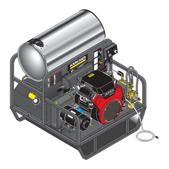
Page 6: Component Identifi Cation
COMPONENT IDENTIFICATION SMALL Flue Adapter Optional 7-10049 Insulation Gasket Optional 7-01471 Water Supply Hose (not included) Detergent Valve 22mm Coupling Adjustable Thermostat Outlet Burner Switch Hour Meter h is C IO e or torc n fl per- K OF . Ne y wh . -
Page 7: Assembly Instructions
ASSEMBLY INSTRUCTIONS Spray Wand High Pressure High Nozzle Pressure Hose 98000800-4 98000800-3 98000800-5 STEP 1: Attach the high pres sure STEP 2: Remove wand end and fi rst STEP 3: Remove shipping cap hose to the spray gun by threading place the o-ring followed by the high and install oil dipstick (Depending twist connect onto spray gun inlet. -
Page 8: Operating Instructions
OPERATING INSTRUCTIONS Dipstick Tank 98000800-9 98000800-10 STEP 1: Check engine oil level. Oil level should be level to the fi ll mark- S T E P 2 : F i l l g a s t a n k w i t h ings on the dipstick. -
Page 9: Operating Instructions
OPERATING INSTRUCTIONS START On-Off Switch Engine Switch 98000800-14 98000800-15 STEP 7: (Electric Start Models) Turn the engine STEP 8: (Electric Start Models) Turn the key to the switch to "Start" po si tion. START position, and hold it there until the engine starts. If the engine fails to start within 5 seconds, release the key, and wait at least 10 seconds before op er at ing the starter again. -
Page 10: Detergents & Clean Up Tips
DETERGENTS & GENERAL CLEANING TECHNIQUES WARNING: Some de ter gents the pump pro tec tor engages and cools the pump by WARNING may be harm ful if in haled or dis charg ing the warm water onto the ground. This in gest ed, caus ing severe nau- ther mal de vice pre vents internal dam age to the pump. -
Page 11: Shut Down & Clean-Up
SHUTTING DOWN AND CLEAN-UP On-Off Switch 98000800-22 98000800- 98000800-24 STEP 1: Re move detergent suc tion STEP 2: Turn off the engine. STEP 3: Tur n off water tube from container and insert into sup ply. one gallon of fresh water. Open de- ter gent metering valve. -
Page 12: Maintenance
MAINTENANCE Winterizing Procedure: PREVENTATIVE MAINTENANCE Damage due to freezing is not covered by warranty. 1. Check to see that water pump is properly Ad here to the following cold weather procedures when- lu bri cat ed. ev er the washer must be stored or operated outdoors 2. -
Page 13: Maintenance
MAINTENANCE tem per a tures and the combustion smoke normally Deliming Coils: as so ci at ed with ma chines in cor po rat ing a spray gun. Periodic flushing of coils or optional float tank is Pe ri od ic in spec tion, to insure that the fuel solenoid rec om mend ed. - Page 14 MAINTENANCE Kärcher ClearFire Oil Burner 6. Remove top tank wrap, bend back insulation tabs and fold back blanket. Burner Air Adjustment: The oil burner on this machine 7. Remove bolts that hold down coil to bottom wrap. is preset for operation at altitudes below 500 feet. If operated at higher altitudes, it may be necessary to 8.
-
Page 15: Troubleshooting
TROUBLESHOOTING PROBLEM POSSIBLE CAUSE SOLUTION Faulty pressure gauge Install new gauge. OPERATING Insuffi cient water supply Use larger supply hose; clean fi lter at water PRESSURE inlet. Old, worn or incorrect spray nozzle Match nozzle number to machine and/or replace with new nozzle. Belt slippage Tighten or replace;... - Page 16 TROUBLESHOOTING PROBLEM POSSIBLE CAUSE SOLUTION BURNER WILL Flex coupling slipping on fuel Replace if needed. NOT LIGHT pump shaft or burner motor shaft (continued from On-Off switch defective Check for electrical current reaching burner assem- previous page) bly with burner switch on. Heavy sooting on coil and burner Clean as required.
- Page 17 TROUBLESHOOTING PROBLEM POSSIBLE CAUSE SOLUTION Improper fuel or water in fuel Replace with clean and proper fuel. WATER Low fuel pressure Increase fuel pressure. TEMPERATURE Weak fuel pump Check fuel pump pressure. Replace pump if needed. Fuel fi lter partially clogged Replace as needed.
- Page 18 TROUBLESHOOTING PROBLEM POSSIBLE CAUSE SOLUTION Oil seal worn Check and replace if necessary. DRIPPING EXCESSIVE Irregular functioning of the valves Check and replace if necessary. VIBRATION IN DELIVERY LINE DETERGENT Air leak Tighten all clamps. Check detergent lines for NOT DRAWING holes.
-
Page 19: Maintenance & Oil Change Charts
PREVENTATIVE MAINTENANCE This pressure washer was produced with the best avail able ma te ri als and quality craftsmanship. However, you as the own er have certain re spon si bil i ties for the correct care of the equip ment. At ten tion to reg u lar pre ven ta tive main te nance pro ce dures will as sist in preserving the per for mance of your equipment. -
Page 20: Exploded Views
EXPLODED VIEW To Burner Pump From Burner Return 68, 69 h is C IO e or torc n fl per- K OF . Ne y wh . RIS E DE rati fl am opé . Ope rate liqu s où o llam . -
Page 21: Exploded Views
EXPLODED VIEW Vanguard with Heat Shield Engine Carb Port To Float Tank To Detergent Valve 98000800-32 HDS 600-606 • 9.800-080.0-AB... -
Page 22: Exploded View Parts List
EXPLODED VIEW PARTS LIST ITEM PART NO. DESCRIPTION 9.802-261.0 Hose, 3/4" Push On 2 ft. ITEM PART NO. DESCRIPTION 9.803-014.0 Coil, Rodless 9.802-151.0 Swivel, 1/2" JIC, Push On 9.803-005.0 Top Wrap, SS ▲ Washer, Snubbing ▲ Trim 9.802-099.0 9.802-071.0 2 ft. ▲... - Page 23 EXPLODED VIEW PARTS LIST (w/Generator) Black, w/o Relief (600.0) ITEM PART NO. DESCRIPTION ITEM PART NO. DESCRIPTION 9.803-009.0 Bracket, Belt Tension 9.803-000.0 Weldment, Face Plate, Long, Black (w/Generator) (602.0, 604.0, 605.0 - w/Gen) ▲ Nut, 5/16", ESNA, NC 9.802-776.0 ▲ Weldment, Face Plate, Short, 9.803-002.0 (w/Generator) Black (600.0, 601.0, 603.0,...
- Page 24 EXPLODED VIEW PARTS LIST ITEM PART NO. DESCRIPTION 8.933-006.0 Switch, MV60 ITEM PART NO. DESCRIPTION 8.753-065.0 Clamp, 1 Ear, #10 9.802-781.0 Nut, 3/8", Flange 8.753-270.0 Reducer, Connector Whiz Loc, NC 1/4" x 3/8" Honda 9.802-776.0 Nut, 5/16", ESNA, NC ▲ Vanguard 8.706-168.0 Elbow, 3/8"...
-
Page 25: Float Tank Assembly & Parts List
FLOAT TANK EXPLODED VIEW 8.903-579.0 98000800-33 To Pump FLOAT TANK PARTS LIST ITEM PART NO. DESCRIPTION ITEM PART NO. DESCRIPTION 9.804-042.0 Tank, Float, 2-1/2 Gallon, 9.803-671.0 Stem, 5" Float Blank 9.802-512.0 Cable, TY, 48" 8.749-328.0 Valve, Float Plastic 9.802-150.0 Anchor, Connector, 1/2" 9.802-162.0 Strainer, 1/2"... -
Page 26: Control Panel, Exploded View & Parts List
CONTROL PANEL EXPLODED VIEW (Reversed View of Label) Detergent Valve Pump h is d fu to rc C IO e or t ad fl am . Do t pe FI RE e es io n. w he . RI e fl ér at e on ui ds... - Page 27 CONTROL PANEL PARTS LIST ITEM PART NO. DESCRIPTION ITEM PART NO. DESCRIPTION 9.803-693.0 Box, Plastic, Back 8.740-345.0 Clamp, Hose, UNI .46-.54 9.802-482.0 Box, Plastic, Front, 9.802-251.0 Hose, 1/4" x 1/2" Fabricated Clear Vinyl 6 ft. 8.750-094.0 Thermostat, 302°F 8.707-058.0 Strainer, 1/4" Brass ▲...
-
Page 28: Hose & Spray Gun Assembly & Parts List
HOSE & SPRAY GUN ASSEMBLY 98000800-35 HOSE & SPRAY GUN PARTS LIST ITEM PART NO. DESCRIPTION ITEM PART NO. DESCRIPTION 8.739-203.0 Hose, 3/8” x 50’, 2 Wire 9.802-299.0 Nozzle, 0005, Red Tuff Flex (603.0, 604.0) 4.775-054.0 EASY! Force Advanced KNA 9.802-300.0 Nozzle, 1505, Yellow (603.0, 604.0) -
Page 29: Burner Specifi Cations
SPECIFICATIONS KÄRCHER CLEARFIRE BURNER SPECIFICATIONS Fuel Nozzle w/100psi Burner Check Burner Fuel Solenoid Model No. Assy No. Valve Ignitor Motor Pump Coil Electrode 1.575-600.0 8.918-919.0 8.754-889.0 8.919-116.0 8.751-074.0 8.754-705.0 9.802-562.0 8.751-342.0 1.575-601.0 8.918-919.0 8.754-889.0 8.919-116.0 8.751-074.0 8.754-705.0 9.802-562.0 8.751-342.0 1.575-602.0 8.920-645.0 8.754-892.0 8.919-114.0... -
Page 30: Pump Specifi Cations
SPECIFICATIONS PARTS SPECIFICATIONS ENGINE PUMP Machine Pump Part Pulley Bushing Engine Engine Model Model Number Unloader Pulley Part # Bushing Part # Part # Pulley Engine 1.575-600.0 KT4540 8.921-714.0 8.715-483.0 2BK100H 9.802-391.0 25MM 9.802-403.0 GX390 8.750-579.0 2BK34H (389 cc) 1.575-601.0 KT6036 8.921-716.0 8.715-483.0... - Page 31 SPECIFICATIONS ENGINE GENERATOR Pulley Bushing Belt Belt Pulley Belt Model Part # Bushing Part # Size Part # Pulley Part # Belt Part # Bushing Part No. 600.0 9.802-382.0 H x 1 9.802-399.0 BX44(2) 8.715-705.0 601.0 9.802-382.0 H x 1 9.802-399.0 BX42(2) 8.715-703.0...
-
Page 32: Clearfi Re "S" Burner Replacement Parts
CLEARFIRE BURNER "S" REPLACEMENT PARTS For best performance specify genuine KNA replacement parts 8.918-919.0 HDS 600-606 • 9.800-080.0-AB... - Page 33 CLEARFIRE BURNER "S" REPLACEMENT PARTS LIST For best performance specify genuine KNA replacement parts ITEM PART NO. DESCRIPTION ITEM PART NO. DESCRIPTION 8.918-454.0 Gasket, Junction Box 8.919-050.0 Burner Housing Assembly 8.750-542.0 Cover, Junction Box 8.751-160.0 Air Guide 8.750-116.0 Block, Terminal, 5 Pole 8.754-705.0 Fuel Pump, Suntec OL35 8.750-817.0...
-
Page 34: Clearfi Re "M/L" Burner Replacement Parts
CLEARFIRE BURNER "M/L" REPLACEMENT PARTS For best performance specify genuine KNA replacement parts 8.920-645.0 54 34 ITEM PART NO. DESCRIPTION ITEM PART NO. DESCRIPTION 8.752-933.0 Motor, 1/5 HP 13.5VDC 8.919-865.0 BurnerHousing Assembly-ML Ametek N1CPM-156 8.754-905.0 Gasket, KNA Burner Pump 8.752-932.0 Motor, 1/7 HP 115V Suntec Emerson K41... - Page 35 CLEARFIRE BURNER "M/L" REPLACEMENT PARTS For best performance specify genuine KNA replacement parts ITEM PART NO. DESCRIPTION ITEM PART NO. DESCRIPTION 8.752-034.0 Flange 1" Tube Assy Burner 8.750-770.0 Screw, 10/32 x 5/8”, Whiz Loc Flange 8.752-035.0 Flange 3" Tube Assy Burner 8.750-816.0 Screw, 10/32 x1/4”...
-
Page 36: Kt.2 Pump Exploded View And Parts List
KT.2 SERIES PUMP EXPLODED VIEW TORQUE SPECS ITEM # FT. LBS. KT.2 PUMP EXPLODED VIEW PARTS LIST ITEM PART NO. DESCRIPTION ITEM PART NO. DESCRIPTION 8.752-825.0 Crankcase 8.707-262.0 Brass Plug 3/8 See Kit Below Plunger Oil Seal See Kit Below Valve Seat See Kit Below O-Ring Ø1.78 x 37.82... - Page 37 KT.2 SERIES PUMP EXPLODED VIEW PARTS LIST ITEM PART NO. DESCRIPTION 9.803-181.0 Bearing Housing 8.752-841.0 Plunger Bolt 8.752-820.0 Bonded Seal 8.753-819.0 Plunger, 18mm 8.752-823.0 Copper Spacer 8.753-820.0 Plunger Rod 8.752-822.0 Connecting Rod Pin 8.752-821.0 Connecting Rod 9.802-889.0 Spring Washer 9.802-937.0 Connecting Rod Screw 9.803-194.0 O-Ring Ø2.62 x 152.07...
-
Page 38: Vrt3 Unloader Exploded View And Parts List
VRT3 UNLOADER EXPLODED VIEW AND PARTS LIST 8.750-297.0, 8 GPM, 2320 PSI 8.750-298.0, 8 GPM, 3630 PSI 8.750-299.0, 8 GPM, 4500 PSI ITEM PART NO. DESCRIPTION 8.750-713.0 Outlet Fitting 8.750-712.0 Knob, Unloader 8.750-709.0 Repair Kit, VRT3, 2320/3630 PSI 8.750-710.0 Repair Kit, VRT3, 4500 PSI (Kit Items: 3, 4, 6, 9-12, 21, 24) Unloader Adjustment Procedures Remove lock nut (Item 19). - Page 40 www.karchercommercial.com Form # 9.800-080.0 • Printed in U.S.A. or Mexico...
Need help?
Do you have a question about the HDS 3.9/30 and is the answer not in the manual?
Questions and answers