Kärcher HDS 5/11 U Service Manual
Hide thumbs
Also See for HDS 5/11 U:
- Manual (316 pages) ,
- Original instructions manual (13 pages) ,
- Instructions manual (312 pages)
Table of Contents
Advertisement
Quick Links
Advertisement
Table of Contents

Related Manuals for Kärcher HDS 5/11 U


Summary of Contents for Kärcher HDS 5/11 U
- Page 1 HDS 5/11 U/UX Service Manual English 5.906-487.0 Rev. 00 (04/10)
-
Page 2: Table Of Contents
Contents Preface Safety instructions Hazard levels Technical Features General Connection performance of appliance Electrical system Drive Pump Booster heater Cleaner Accessories Parts of the system View from the front, appliance with hose drum View from the front, appliance without hose drum Rear view View from below View from the front left, appliance hood removed... - Page 3 5.11 Motor/pump unit 5.11.1 View from above 5.11.2 Left view 5.11.3 Sectional illustration 5.11.4 Cross section of pump head front view 5.11.5 Single parts, pump head 5.11.6 Electric box, motor (open) 5.11.7 Remove the ventilator wheel of the burner blower 5.11.8 Remove the safety block 5.11.9...
-
Page 4: Preface
Preface 3.2 Connection performance of appliance 2.2 kW – Good service work requires extensive and practice- oriented training as well as well-structured training 3.3 Electrical system materials. Appliance switch with adjustments for cold water/ – Hence we offer regular basic and advanced training hot water programmes covering the entire product range for all Pressure switch... -
Page 5: Parts Of The System
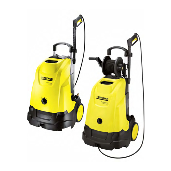
Parts of the system 4.1 View from the front, appliance with hose drum 1 Hand spraygun 10 Water inlet with water fine filter 2 Hand lever 11 Bearing wheel 3 High pressure hose 12 Carrying handle 4 Push handle 13 High pressure hose output 5 Handgun storage clip 14 Carrying handle 6 Hose drum... -
Page 6: View From The Front, Appliance Without Hose Drum
4.2 View from the front, appliance without hose drum 1 Hand spraygun 14 Power switch 2 Hand lever 15 Exhaust nozzle, on-demand heater 3 High pressure hose 4 Push handle 5 Handgun storage clip 6 Cover 7 Spray lance 8 High-pressure outlet 9 Water inlet with water fine filter 10 Bearing wheel 11 Carrying handle... -
Page 7: Rear View
4.3 Rear view 1 Push handle 2 Storage compartment for mains cable 3 Power cord with plug 4 Lock for fuel tank 5 Fill indicators of fuel tank 6 Storage for rotor nozzle 7 Kick plate to tilt the appliance 8 High-pressure outlet 9 Water inlet with water fine filter 10 Detergent suction and dosing with fine filter... -
Page 8: View From Below
4.4 View from below 1 Deflection rollers high pressure hose 2 Support leg 3 Carrying handle 4 Guide for high pressure hose 5 High pressure hose 6 Axle 7 Air suction for motor cooling 8 Air suction for burner blower English 5.906-487.0 Rev. -
Page 9: View From The Front Left, Appliance Hood Removed
4.5 View from the front left, appliance hood removed To remove the appliance hood, you must unlock it by means of a screwdriver. Unlock the appliance hood from above using a screwdriver and remove it. 1 High pressure line 8 Electric box for high pressure pump 2 Ignition transformer 9 Electronics system... -
Page 10: View From The Front Right, Appliance Hood Removed
4.6 View from the front right, appliance hood removed 1 Exhaust nozzle, on-demand heater 2 Exhaust temperature sensor 3 Fuel line 4 Continuous heater 5 Aeration/deaeration of the fuel tank 6 Fuel tank 7 Electronics system 8 Air guidance burner blower 9 Air volume setting 10 Fuel filter 11 Screw connection of fuel line... -
Page 11: Function
Function 5.1 Functional diagram 1 Water connection 18 Fuel nozzle 2 Suction hose with filter and backflow valve (option) 19 Ignition electrodes 3 Open container 20 Continuous heater 4 Water supply hose 21 Heating coil, on-demand heater 5 Water fine filter 22 Exhaust nozzle, on-demand heater 6 Pressure switch 23 Exhaust temperature sensor... -
Page 12: Power Switch
5.2 Power switch 1 Switch position "OFF" "OFF": Appliance is switched off – 2 Switch position "Cold water operation" "Cold water operation": High pressure cleaner – function without on-demand heater 3 Switch position "Hot water operation" "Hot water operation": High pressure cleaner func- 4 Power switch –... -
Page 13: Electronics System
5.4 Electronics system Open the switchbox Lift the electric box out of its holder by alternatingly lifting it toward the top. Bend up the four side tabs and remove the top part. 1 Electronics system 2 Side tabs 3 Top part of electric box 1 Exhaust temperature monitor 280°C 7 Electronics system... -
Page 14: Burner Blower With Fuel Pump
5.5 Burner blower with fuel pump 1 Air guidance to the on-demand heater 2 Slider, air volume adjustment 3 Stop screw, air volume adjustment 4 Return to fuel tank 5 Fuel hose supply to the fuel pump 6 Connecting cable of solenoid valve and fuel pump 7 Access opening of fuel pressure adjustment 8 Fuel pump 9 Suction opening, burner blower... - Page 15 Burner blower The blower supplies the burner with combustion air. The slider is used to set the air volume to optimal combustion values. The blower wheel is mounted to the motor shaft by means of a fitting key. 1 Stop screw 2 Air slider 3 Mark to adjust the air slider English 5.906-487.0 Rev.
-
Page 16: Booster Heater
5.6 Booster heater 1 Ignition transformer Type plate The type plate of the heating coil can be read through 2 Protective conductor the exhaust stack. 3 Fuel nozzle holder 4 Burner cover 5 Exhaust nozzle, on-demand heater 6 Heating coil 7 Exhaust temperature sensor 8 Capillary exhaust temperature monitor 9 Connection for air pressure measurement... - Page 17 1 Ignition electrodes The water from the high pressure pump enters the in- terior heating coil spiral, is heated while flowing 2 Fuel nozzle through and exits to the bottom from the heating coil 3 Boiler floor spiral. 4 Boiler input The fuel is vaporised by the fuel nozzle and ignited by 5 Air supply from burner blower the spark of the ignition electrodes.
-
Page 18: Remove Burner
The boiler floor is made of fire-resistant insulating concrete. It prevents a radiation of the heat and is used to reroute the flames. The adjustment of the burner to good exhaust values is achieved via the air slider on the blower (air vol- ume) and with the adjustment screw on the fuel pump (fuel pressure). -
Page 19: Burner
5.7 Burner 1 Ignition electrodes Note This appliance does not have a sight glass in the 2 Fuel nozzle holder burner cover. 3 Fuel nozzle, spray angle 45° or 60°, depending on In order to ensure a safe ignition of the injected fuel, the type of appliance the adjustment dimensions must be strictly adhered 4 Screw... -
Page 20: Disassemble The Burner
5.7.1 Disassemble the burner Pull of the flame ring, if it does not remain in the To replace the burner nozzle, remove the nut and boiler during removal. take out holder with the fuel nozzle. 1 Ignition electrodes 1 Ignition transformer 2 Screw of the ignition electrodes 2 Burner cover... -
Page 21: Hand Spray Gun And Triple Nozzle
5.8 Hand spray gun and triple nozzle 5.8.1 Hand spraygun 1 Replacement gun 2 Spray lance 3 Series gun Note There are no spare parts available for the series gun. There are Disis spare parts available for the series gun. English 5.906-487.0 Rev. -
Page 22: Triple Nozzle
5.8.2 Triple nozzle The triple nozzle can be adjusted to three different To adjust the needed type of nozzle, the gun must be settings. closed and the nozzle head must be rotated to the By rotating the nozzle head, you can switch between settings shown above (A, B, C). -
Page 23: Remove The Top Part With The On-Demand Heater
5.9 Remove the top part with the on-demand heater The entire top part must be removed to gain access 5.9.2 Close the fuel lines to the high pressure pump. A workshop lifting platform is recommended for this In order to prevent fuel from leaking while removing procedure. -
Page 24: Disconnect The Connections On The Burner
5.9.4 Disconnect the connections on the pump head Pull the detergent hose off of the pump head. 1 Fuel line to burner 2 Fuel line from the fuel pump 5.9.3 Disconnect the connections on the burner 1 Detergent hose ... -
Page 25: Loosen The Base Plate Of The On-Demand Heater
5.9.5 Loosen the base plate of the on-demand heater Remove two screws on the base plate of the on- demand heater. 1 Electronics system Disconnect the connector of the temperature con- 1 Base plate for on-demand heaters trol 95°C. 2 Screw ... - Page 26 Pull out the safety clip of the high pressure line. 1 High pressure line Remove the bottom of the appliance from the on- demand heater. 1 Safety block 2 Safety clip 3 High pressure line Remove the safety block. 1 Temperature controller 95°C 2 Connector temperature controller 95°C 1 Safety block...
-
Page 27: Floor Group
5.10 Floor group 1 Storage for spray pipe 2 Holding plate for the base plate of the on-demand heater 3 Water inlet with water fine filter 4 Electric box, motor 5 Blind plug (do not remove, do not fill in liquids) 6 Holder, electric box 7 Cool air guidance and motor cover 8 Burner blower outlet... -
Page 28: Remove The Motor/Pump Unit
5.10.1Remove the motor/pump unit Remove 6 screws from the motor cover. Remove the motor cover. 1 Motor/pump unit 2 Side motor intake (2x) 3 Centre motor intake (2x) 1 Screws, motor cover 4 Fuel pump 2 Cool air guidance and motor cover ... -
Page 29: Left View
5.11.2Left view 1 Ventilator wheel, burner blower 2 Ventilator wheel, motor cooling 3 Motor intake 4 Water inlet with water fine filter 5 Fastening screw, water inlet 6 Holding clip, water inlet 7 Pump head screws 8 Pump head 9 Holding plate, pressure valves 10 Connection detergent suction 11 Reed switch, lack of water fuse 12 Safety valve... -
Page 30: Sectional Illustration
5.11.3Sectional illustration 1 Pressure switch 2 Switch cam 3 Overflow valve (control piston, pressure switch) 4 Capacitor 5 Axial ball bearing, swash plate 6 Motor bearing, front (A bearing) 7 Shaft seal ring, motor shaft 8 Motor winding (stator) 9 Solenoid (rotor) 10 Motor bearing, rear (B bearing) 11 Ventilator wheel, motor cooling 12 Motor shaft... -
Page 31: Cross Section Of Pump Head Front View
5.11.4Cross section of pump head front view 1 Pressure spring 2 Sphere 3 Connection of detergent hose 4 Injector 5 Holding plate 6 Pressure holding valve 7 Pressure valve 8 Stopper 9 Suction area 10 Piston 11 Cylinder head screws 12 Connection, safety block English 5.906-487.0 Rev. -
Page 32: Single Parts, Pump Head
5.11.5Single parts, pump head 1 Cap 2 Pressure valve 3 Valve seat 4 Pump head 5 Restrictor 6 Suction valve 7 High pressure seal 8 Connecting sleeve English 5.906-487.0 Rev. 00 (04/10) -
Page 33: Electric Box, Motor (Open)
5.11.6Electric box, motor (open) 1 Electric box, motor 2 Seal 3 Cable to the electric box, appliance 4 Pressure switch 5 Leaf spring 6 Switch cam 7 Capacitor 8 Connection, protective conductor 9 Connecting cable, motor 10 Fastening screws, electric box Note To remove the pump head, the electric box must be taken out - otherwise, the control piston of the pres-... -
Page 34: Remove The Ventilator Wheel Of The Burner Blower
5.11.7Remove the ventilator wheel of the burner 5.11.9Safety block, front view blower Remove the screw and pull the ventilator wheel off. 1 Fastener, reed switch 2 Reed switch 3 Connection to the pump head 4 Safety valve 1 Screw 2 Ventilator wheel, burner blower Note When installing the reed switch, make sure that the... -
Page 35: Safety Block, Cross Section Drawing
5.11.11Safety block, cross section drawing 5.11.12Remove the detergent injector and the pressure holding valve The detergent injector is screwed into the pump head with a thread. Unscrew the detergent injector. Remove the pressure holding valve. 1 Pump head 2 Detergent injector 1 Locking screw, lack of water fuse 2 Spring... -
Page 36: Remove The Water Inlet
5.11.13Remove the water inlet 5.11.14Remove the control piston for the pres- sure switch. Remove the fastening screw of the water inlet on the pump head. Note The removal of the pressure switch control piston is Pull the holding clip downwards. not required to remove the pump head and the piston ... -
Page 37: Disassemble The Pump
5.11.15Disassemble the pump Remove the pump head The pump head screws go through the piston casing and are screwed into the motor casing. Therefore, in order to be able to remove the pump head without having to remove the piston casing, the piston housing must be fastened to the motor casing with two installation screws. - Page 38 5.11.16Test run After repairing the pump, you must perform a test run to check the pump for leaks and proper operation. This can be done without connecting the on-demand heater. Assemble the motor/pump unit and place it into the chassis without the fuel pump. ...
-
Page 39: Basic Settings And Service Procedures
Basic settings and service procedures 6.1 Brief overview, dismantling / assembly 6.1.1 Upper section The entire top part must be removed to perform the Work steps for assembly: following work: Place the pump kit into the bottom part with all rub- Working on the pump ber buffers. -
Page 40: Back Of Appliance
6.1.2 Back of appliance The back of the appliance must be removed for the following work: Working on the heating coil – Working on the heating coil connections – Working on the high pressure lines – Working on the mains cable –... -
Page 41: Remove The Hose Drum
6.2 Remove the hose drum Remove high pressure hose as described in chap- ter 5.9.1Remove high pressure hose (UX version only) . Remove the screws on the pushing handle and pull the pushing handle off toward the top. 1 Hose drum 2 Screws 1 Push handle... -
Page 42: Replace The Seal Of The Rotary Grommet
6.2.1 Replace the seal of the rotary grommet Replace seals and grease with PFAE grease Pull the crank straight off of the hose drum and re- (6.288-088). move the side part. Check the axle and the knot for wear in the area of the seals. -
Page 43: Remove The Rear Wall
6.3 Remove the rear wall 6.4 Settings, burner Note Remove the tank lid. An accurate basic adjustment of the burner is only Remove the rear wall (2 screws). possible if the heating coil was previously thoroughly Replace the tank lid. desooted and the deposits were removed.Eine ex- akte Grundeinstellung des Brenners ist nur möglich, wenn die Heizschlange vorher gründlich entrußt und... -
Page 44: Adjust Safety Valve
6.5 Adjust safety valve 1 Adjusting screw 2 High pressure connection 3 Safety valve (built into the safety block) 4 Drain bore Increase the opening pressure: Turn the adjustment screw in a clockwise direc- tion. Decrease the opening pressure: ... -
Page 45: Circuit Diagram 0.089-212
Circuit diagram 0.089-212 KALT / COLD / FROID / FRÍO WARM / WARM / CHAUD / CALIENTE English 5.906-487.0 Rev. 00 (04/10) -
Page 46: Troubleshooting
Troubleshooting Fault Remedial action Unit does not work No mains power. Check the mains connection. – Check/replace the appliance switch. – Overflow valve / pressure switch stuck - check, grease, replace. – Motor overloaded, overheated; switch off the appliance to "0/OFF" and –... -
Page 47: Technical Specifications
Technical specifications Technical specifications Preliminary values Appliance number 1.064-001 / 1.064-002 Description HDS 5/11 U/UX Mains voltage / phase number V / Ph 230 / 1 Supply voltage, permissible voltage tolerance Frequency Current pickup, full load (after 10 min.) Connection output... -
Page 48: Special Tools
Appliance type Appliance no.: Circuit diagram operating instruc- Spare parts list tions HDS 5/11 U 1.064-001 0.089-212 5.963-348 5.971-057 HDS 5/11 UX 1.064-002 0.089-212 5.963-348 5.971-057 The current technical specification sheets and circuit diagrams will be included in the next version of the spare parts CD DISIS/DISIPlus and in the kaercher- inside (https://kaercher-inside.com). - Page 49 Puller tool, blower wheel 6.816-069 Adapter line (Swivel), alternative adapt- 4.421-739 er hose, 0.5 m long, connection high 6.391-522 pressure hose M22x1.5 to the safety block. Ohne Abbildung Installation screws, piston guidance 6.303-098 Air pressure gauge; we recommend Cannot be (2x M5x30) "Testo 510", order no.
-
Page 50: Tightening Torques
11 Tightening torques Detergent connection on the injector 12 - 15 Cylinder head screws 18 - 23 Swash plate, screw glued 12 - 15 Lock screws on holding plate of overflow unit 8 - 9 Electric box on motor 8 - 9 Safety block on cylinder head 6 - 8 Locking screw, lack of water fuse...
Need help?
Do you have a question about the HDS 5/11 U and is the answer not in the manual?
Questions and answers