Table of Contents
Advertisement
Quick Links
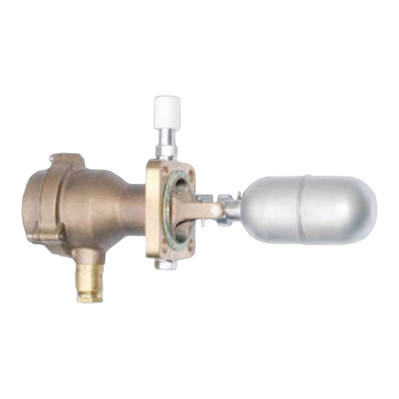
Dimensions
Measures in mm / inch
Test knob
Test knob
V, W, X, Y = connecting parts
V + W = max. 750 mm
X + Y = max. 750 mm
standard value for W = 75 mm
8
Test knob
Operating Instructions
Level Switch
UNS-RG-040
1
Intended Applications...................................................................................................... 2
2
Safety Instructions........................................................................................................... 2
3
Standards.......................................................................................................................... 3
4
Warranty/Guaranty........................................................................................................... 3
5
Storage.............................................................................................................................. 3
6
Installation/Commissioning ............................................................................................ 4
7
Maintenance/Cleaning ..................................................................................................... 5
8
Principle Of Operation...................................................................................................... 7
9
Technical Data.................................................................................................................. 7
Barksdale GmbH
Dorn-Assenheimer Straße 27
D-61203 Reichelsheim
Tel.:
+49 (6035) 949-0
Fax:
+49 (6035) 949-111 and 949-113
email:
info@barksdale.de
Internet: www.barksdale.de
Art. no.: 923-1432
Index C, 14.03.2008
Specifications are subject to
changes without notice!
1
Advertisement
Table of Contents

Related Manuals for Barksdale UNS-RG-040


Summary of Contents for Barksdale UNS-RG-040
- Page 1 Dimensions Operating Instructions Level Switch Test knob UNS-RG-040 Measures in mm / inch Test knob Test knob Intended Applications...................... 2 Safety Instructions......................2 Standards.......................... 3 Warranty/Guaranty......................3 Storage..........................3 Installation/Commissioning .................... 4 Maintenance/Cleaning ..................... 5 V, W, X, Y = connecting parts Principle of Operation......................
- Page 2 Nonobservance may cause injuries to health or material damage. The standards applied during development, manufacture and configuration are listed in the CE Barksdale GmbH cannot be held liable for any damage resulting from incorrect use. conformity and manufacturer's declaration. Observe also the applicable national safety instructions for assembly, commissioning and operation of the level switch.
- Page 3 Electrical connection Installation/Commissioning We recommend to connect the ground / protective conductor to the ground terminal marked in the casing. DANGER WARNING Prior to any work on electrical components disconnect them from power supply. The electrical connection may only be made by trained expert staff! Heat-resisting cables must be used on switch head and cable gland if the switch is subjected to high temperatures.
- Page 4 Checking the dry side - switch body Principle of Operation 1. Unscrew the casing top. The sturdy gunmetal casing with integrated connection flange is the core part of the switch. The 2. Check the gasket. casing top is sealed by means of an O ring and thus has an IP 56 protection system. The 3.
Need help?
Do you have a question about the UNS-RG-040 and is the answer not in the manual?
Questions and answers