Table of Contents
Advertisement
Quick Links
Electrical Ratings Type KD1
Silver contacts
Inductive load
30 V =
3.0 A
IMPORTANT
Data only valid for application in non-explosive atmosphere.
We recommend to use a prefuse of the maximum current rating from the table above according to
the load switched.
As the lamp load is hardly relevant in the field we abstain from relating details. More information on
request.
Electrical Ratings Type KLK/KLM
Silver contacts
Inductive load
30 V =
3.0 A
IMPORTANT
Data only valid for application in non-explosive atmosphere.
We recommend to use a prefuse of the maximum current rating from the table above according to
the load switched.
We recommend gold plated contacts for all intrinsically safe and other applications with low
voltage/power.
Operating life time
Normal expected service life (expressed in the number of cycles over the full adjustment range) is
appr. 1 million for KLK/KD1 the pressure switches and for the KLK approx 0.5 million. This may be
extended to 2.5 million cycles for piston switches max. if only a part of the adjustment range is used
(about 20%).
Switch sensor life may also be effected negatively by:
Media not compatible with the wetted materials.
Too high switch cycling speed or more than 60 cycles per minute.
System cycling pressure exceeding the top of the adjustable range.
Too high electrical ratings
The proof pressure must never be exceeded, otherwise the switch may be damaged. Careful
selection of the pressure range ant the electrical rationgs can have a positive effect on the service
life of the switch.
Switching rate:
KLM: max 30/min
12
Resulting load
5.0 A
Resulting load
Gold plated contacts
5.0 A
U
30 V =
max
I
400 mA
max
(U·I)
0.12 VA
max
KLK/KD1: max 60/min
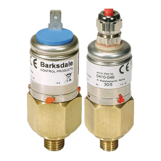
Operating Instructions
Compact Pressure Switches Type KD1.../KLK.../KLM...
1
Intended Applications ................................................................................................... 2
2
Safety Instructions......................................................................................................... 2
3
Standards ....................................................................................................................... 3
4
Warranty/Guaranty......................................................................................................... 3
5
Transport/Storage .......................................................................................................... 4
6
Installation/Commissioning .......................................................................................... 4
7
Maintenance/Cleaning ................................................................................................... 7
8
Technical Data................................................................................................................ 8
Barksdale GmbH
Dorn-Assenheimer Straße 27
D-61203 Reichelsheim
Phone:
+49 (6035) 949-0
Fax:
+49 (6035) 949-111 and 949-113
email:
info@barksdale.de
Internet: www.barksdale.de
Art. No.: 923-0181
Index I, 29.08.2011
Specifications are subject to changes
without notice!
1
Advertisement
Table of Contents

Related Manuals for Barksdale KD1 Series


Summary of Contents for Barksdale KD1 Series
-
Page 1: Table Of Contents
2.5 million cycles for piston switches max. if only a part of the adjustment range is used (about 20%). Switch sensor life may also be effected negatively by: Barksdale GmbH Media not compatible with the wetted materials. -
Page 2: Intended Applications
Intended Applications IMPORTANT The pressure switches are specifically applied for monitoring and controlling of operations using maximum and minimum pressures. A micro switch triggers an electrical signal when minimum or Refers to important information essential to the user. maximum pressure are reached. DANGER Disposal The equipment must be disposed of correctly in accordance with the local regulations for... -
Page 3: Transport/Storage
Transport/Storage Contact Protection The micro switches used are normally suitable for both direct and alternating current operation. CAUTION Inductive, capacitive and lamp loads may, however, considerably reduce the life expectancy of a micro switch and, under extreme circumstances, even damage the contacts. Severe shock and vibrations should be avoided during transport. -
Page 4: Maintenance/Cleaning
Wiring Code for all Types (Contact status at atm. pressure) Use in Hazardous Locations The pressure switches to be used in hazardous locations are principally designed for intrinsically KD1-K2 safe circuits i following the applicable regulations and are provided with a blue plate bearing the = green words "For intrinsically safe Ex i application“. -
Page 5: Technical Data
Technical Data Silicone cable 3×0.5 mm ; 600 mm long Plug connector, 3-pin + E, EN 175301-803 C See data sheet 31 (1.22) Dimensions Ø16 in mm (inch) Plug (0.63) Silicone cable 3×0.5 mm ; 600 mm long Spade connector 6.3 - DIN 46244; green Spade connector SW15 R 1.5 (0.06) - Page 6 Approval data for pressure switches type KLK/KLM-…-K2 Adjustable ranges Approval: II 1 G D Ex ia IIC T6 Order code Adjustment Max. proof Max. operating Max. hysteresis ranges pressure [bar] pressure [bar] (end of range) Ex ia D 20 T100 Certificate no.: ISSeP08ATEX016X Pressure...
Need help?
Do you have a question about the KD1 Series and is the answer not in the manual?
Questions and answers