Table of Contents
Advertisement
Quick Links
11 Technical Data
BPS3000
Measuring element
Ceramic sensor, optional: piezoresistive sensor
at 600 bar (9000 psi): piezoresistive sensor only
Version with relay-output; piezoresistive sensor only
Measuring ranges
0 ... 0.2 bar to 0 ... 600 bar, 0 ... 3 psi to 0 ... 9000 psi, gauge pressure
0 ...1 bar to 0 ... 10 bar, 0 ...15 psi to 0 ... 150 psi, absolute
Display
4-digit 14-segment LED display, red, digit height 9 mm
Transistor switching outputs PNP
1 or 2 x NO/NC function (programmable),
adjustable switching time delay 0 ... 50 s
Relay-output
2 x, max. 60V/1A/30W
Operating temperature range
-10 ... +70 °C / +14 ... +158 °F
Media temperature range
-25 ... +100 °C / -13 ... +212 °F
Storage temperature range
-30 ... +80°C / -22 ... + 176 °F
Process connection
G ¼" M, G ½" front-flush, 1/4" NPT, 1/2" NPT, 7/16 - 20 UNF JIC 37°, 7/16
SAE-4, Cetop, G ½" with enlarged bore diameter, G ¼" internal threat, ¼"
BSPT
2)
Protection system
/class
IP65, IP67; UL-Type 6, 4X, 3R (dependant on specification) / III
Electrical connection
M 12x1, 4/5/8-pin (depending on output code)
Power supply
15 ... 32 V DC / relay-output: 20-32 VDC
1 )
Approvals
cULus
(pending for IO-Link devices)
For further technical data and options please refer to the data sheets
1)
Conditions of use: 60°C max. ambient, power supply max. 28 V DC
2)
The stated ingress protection only applies when plugged in using mating connectors that have the appropriate
ingress protection.
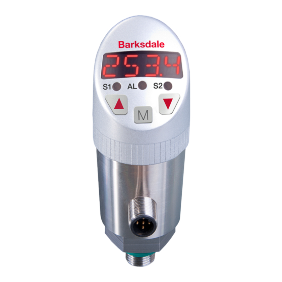
Operating and display elements/Dimensions
1
12
Dimensions (example) in mm (inch)
Item 1: LEDs
AL
(red) - Alarm
2
S1
(red) - switching point 1
S2
(red) - switching point 2
Item 2: Keys
For functions refer to chapter 8
"Programming" on page 5.
Operating Instructions
Dual Pressure Switch BPS3000
Operating Instructions ............................................................................................................ 1
1
Intended Applications .................................................................................................... 2
2
Safety Instructions ......................................................................................................... 2
3
Standards ........................................................................................................................ 2
4
Warranty/Guarantee ....................................................................................................... 2
5
Installation ...................................................................................................................... 2
6
Commissioning/Operation ............................................................................................ 3
7
IO-Link version ............................................................................................................... 3
8
Programming .................................................................................................................. 3
8.1
Parameters ............................................................................................................. 4
8.2
Menu Structure ....................................................................................................... 5
9
Maintenance/Cleaning ................................................................................................... 6
10
Decommissioning .......................................................................................................... 6
11
Technical Data .............................................................................................................. 12
Barksdale Inc.
3211 Fruitland Avenue
Los Angeles, CA 90058-0843
U.S.A.
Phone: (323) 589-6181
Fax:
(323) 589-3463
e-mail: sales@barksdale.com
www.barksdale.com
Art. no.: 923-1966
Index H, 11.06.2018
Software version: 1.2 or higher
Specifications are subject to changes without notice!
Barksdale GmbH
Dorn-Assenheimer Straße 27
D-61203 Reichelsheim
Phone:
+49 (6035) 949-0
Fax:
+49 (6035) 949-111 and 949-113
e-mail:
info@barksdale.de
www.barksdale.de
1
Advertisement
Table of Contents

Related Manuals for Barksdale BPS3000


Summary of Contents for Barksdale BPS3000
-
Page 1: Table Of Contents
Operating Instructions 11 Technical Data Dual Pressure Switch BPS3000 BPS3000 Measuring element Ceramic sensor, optional: piezoresistive sensor at 600 bar (9000 psi): piezoresistive sensor only Version with relay-output; piezoresistive sensor only Measuring ranges 0 ... 0.2 bar to 0 ... 600 bar, 0 ... 3 psi to 0 ... 9000 psi, gauge pressure 0 …1 bar to 0 …... -
Page 2: Intended Applications
No liability is assumed for any damage resulting therefrom, or any consequential damage. material damage. In the operating instructions the seriousness of the potential risk is designated by the following signal words: See also Barksdale “Standard Terms and Conditions” Installation DANGER CAUTION Refers to imminent danger to users. -
Page 3: Commissioning/Operation
Electrical connection is to be carried out dependent on the type of switch (see name label) according to the chart below. Improper connections may cause malfunctions or incorrect switch outputs and WARNING damage to the unit. Be aware of the fact that in case of operation with higher temperatures the casing surface may Electrical connection become very hot! Plug... -
Page 4: Parameters
8.1 Parameters Parameter 14-segment display Description Parameter 14-segment display Description AEP** Analog end value SP1/SP2* Hysteresis function: Switching point of solid state contact dPA** Damping of analog output FH1/FH2* Window function: Window High solid state contact ErS.A** Error signal of analog output Values: <... -
Page 5: Menu Structure
8.2 Menu Structure Factory setting Factory setting Display Unit dr2* Hysteresis delay, output 2 SP1 / FH1 Switching point 1 0... x bar Output 1 Off - Hno - Hnc - Fno - rP1 / FL1 Hysteresis 1 0... x bar Output 2 Off - Hno - Hnc - Fno -... -
Page 6: Maintenance/Cleaning
Maintenance/Cleaning Factory setting Maintenance The pressure switch requires no maintenance. Maximum peak value Delete WARNING Check the switch for functioning at regular intervals. Minimum If the switch does not work properly, stop operation immediately. peak value Delete Cleaning Offset (10 % CAUTION of measuring range)
Need help?
Do you have a question about the BPS3000 and is the answer not in the manual?
Questions and answers