
Related Manuals for Barksdale Dynalco SST7200


Summary of Contents for Barksdale Dynalco SST7200
- Page 1 3211 Fruitland Ave Los Angeles, CA 90058 SST7200 SST7400 Speed Switch / Transmitter Installation and Operation Manual Rev. G P/N 145F-13129 PCO – 00010927 (c) Copyright 2015, Barksdale, Inc. All Rights Reserved Published: Oct 20, 2015...
- Page 3 All equipment doors must be closed and protective covers must be in place unless qualified personnel are performing maintenance. Shutdown / alarms should be tested monthly for proper operation (see page 16) Please see page 18 for CSA specific installation instructions. This manual covers both models SST7200 and SST7400: Speed Switch / Transmitter w/ 4 –...
-
Page 4: Specifications
Specifications 1) INPUT SUPPLY VOLTAGE: 10 - 36 VDC, maximum 10 W 2) FREQUENCY INPUT: 0 – 50 KHz a. Input Signal Frequency Range: b. Waveforms: Accepts sinusoidal or square wave (positive or zero- crossing) c. Input Signal Sensitivity: 25 mV to 1.0 VRMS (selectable), Maximum allowed is 50 VRMS d. - Page 5 5) RELAY OUTPUTS: a. Type: SPDT relay contacts (isolated dry contacts) b. Contact Rating: 6.0 Amps @ 28 VDC or 115 VAC 1/8 HP @ 120 / 240 VAC (100,000 cycles) 1.5 / 0.8 Amps @ 120 / 240 VAC, Pilot Duty (100,000 cycles) 3.8 / 1.9 Amps @ 120 / 240 VAC general Use (100,000 cycles)
- Page 6 Installation: The SST7200 & SST7400 have an integral latch on the rear of the device for installation on a standard 35 mm DIN rail. This device is OPEN type equipment that must be used within a suitable end-use system enclosure, the interior of which is accessible only through the use of a tool. The suitability of the enclosure is subject to investigation by the local Authority Having Jurisdiction at the time of installation.
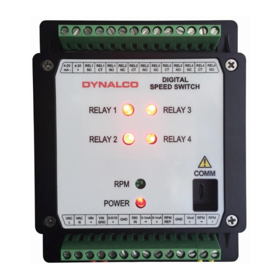
- Page 7 Terminal Connections All connections are made via the terminal blocks on the front of the unit. Top Terminal Block Connections Description 4-20 4-20 mA Proportional Output (-) 4-20 4-20 mA Proportional Output (+) REL1 Normally-Closed Relay Contact REL1 Relay Common REL1 Normally-Open Relay Contact REL2...
- Page 8 Bottom Terminal Block Connections Description 120 VAC (Hot) 120 VAC (Neutral) 10 - 36 VDC Supply (+) Supply Ground (-) 0-5/10 0-5 or 0-10 VDC Proportional Output 0-5/10 0-5 or 0-10 VDC Proportional Output (- Digital Input for resetting latched relay 0-1mA 0-1 mA local meter output (-) 0-1mA...
-
Page 9: Outline Dimensions
Outline Dimensions... - Page 10 Dynalco SST7200 & SST7400 Software The Dynalco host software provides serial communication between a PC or laptop and the SST7200 & SST7400. The software is compatible with Windows XP, Vista and Windows 7 operating systems. The SST7200 & SST7400 must be connected via provided Dynalco P/N 270A-105574 serial communication cable.
- Page 11 RPM Signal The RPM Signal needs to be programmed prior to all other settings. The SST7200 & SST7400 are capable of accepting input signals from 2-wire (also known as variable reluctance) magnetic pickups as well as 3-wire (powered, TTL or hall-effect) type sensors.
- Page 12 Signal Lost The Signal Lost function is defined as the absolute maximum allowable period (time between input pulses in milliseconds) before an under speed relay is tripped. Similar to the Max Wave Duration described in the previous step, the Signal Lost setting is necessary for low speed applications where there is a programmed under speed trip.
- Page 13 Open Pickup The Open Pickup tab allows the user to select which relay (if any) will activate if an open pickup is sensed. Enable o Check this box to enable Open Pickup option Trip o Select either Setpoint 1 or 2 for the SST7200 o Select either Setpoint 1, 2 ,3 or 4 for the SST7400...
- Page 14 Analog Output The analog output tab is used to define the RPM range of the proportional 4 – 20 mA output. RPM Zero o Set to the RPM value corresponding to 4 mA output. o Normally set to 0 RPM but can be set to any value as long as it is lower than the RPM span.
- Page 15 Setpoints 1 & 2 (plus 3 & 4 for SST7400) The Setpoint tabs allow configuration of relay setpoints and relay logic. Enable o Check this box to enable each setpoint Relay Normal State o This is the normal relay state when not tripped o Either select normally Energized or normally De-Energized WARNING: For critical applications, it is highly recommended to configure the Relay Normal State as “normally...
- Page 16 Program Following initial configuration of the unit or any setting changes, you will need to select “Program” to program the new settings to the SST7200 / SST7400. Save File Selecting “Save File” allows the new settings to be saved to a file location on the...
- Page 17 Load File Any spec files that have been saved to the PC can be loaded to the SST7200 & SST7400 application by selecting “Load File.” Following this, you will need to select “Program” write configuration SST7200 & SST7400. Import Settings Selection of “Import Settings”...
- Page 18 This equipment is suitable for installation in Class I, Division 2, Groups A, B, C, and/or D hazardous locations, or nonhazardous locations only. “WARNING - EXPLOSION HAZARD - Substitution of components may impair suitability for Class I, Division 2.” “AVERTISSEMENT - RISQUE D'EXPLOSION - La substitution de composants peut rendre ce matériel inacceptable pour les emplacements de Classe I, Division 2.”...
Need help?
Do you have a question about the Dynalco SST7200 and is the answer not in the manual?
Questions and answers