
Related Manuals for Fluke Versiv


Summary of Contents for Fluke Versiv
- Page 1 Versiv ™ Cabling Certification Product Family Users Manual April 2014, Rev. 3 8/2015 ©2014-2015 Fluke Corporation All product names are trademarks of their respective companies.
- Page 2 LIMITED WARRANTY AND LIMITATION OF LIABILITY Each Fluke Networks product is warranted to be free from defects in material and workmanship under normal use and service unless stated otherwise herein. The warranty period for the mainframe is one year and begins on the date of purchase.
-
Page 3: Table Of Contents
Supplements and Updated Manuals ......3 Kit Contents ..............3 Certifications and Compliance ........4 Safety Information ...........5 For the Versiv Main Unit ..........5 For DSX Modules ............7 For CertiFiber Pro OLTS Modules ......8 For OptiFiber Pro OTDR Modules ......10 AC Adapter and Battery ..........11 Charge the Battery ...........11... - Page 4 Versiv Cabling Certification Product Family Users Manual About LinkWare Applications ........23 LinkWare PC Cable Test Management Software ... 23 The LinkWare Live Web Application ...... 23 LinkWare Stats ............23 Chapter 2 Certify Twisted Pair Cabling Overview of Features ............. 25 Connectors, Keys, and LEDs ...........
- Page 5 Chapter 4 Clean Fiber Endfaces Always Clean Endfaces Before Tests ......73 How to Use a Fluke Networks IBC OneClick Cleaner ..76 How to Use Wipes, Swabs, and Solvent ......78 To Clean Bulkhead Connectors ........78 To Clean the Optical Connectors on the Modules .79 To Clean Fiber Adapters ..........79...
- Page 6 Versiv Cabling Certification Product Family Users Manual Requirements for Reliable Fiber Test Results ....102 About the Reference for Fiber Tests ....... 103 When to Set the Reference ......103 Good Reference Values ........104 How to See the Reference Values ....105 About Test Reference Cords and Mandrels ....
- Page 7 Contents Step 2: Measure the Loss of the Test Reference Cord You Will Add ...........139 Step 3: Do an Autotest in Far End Source Mode ..140 Autotest Results for Far End Source Mode .....141 Bi-Directional Tests ............143 Chapter 7 Use the OTDR Overview of Features ............145 Connectors, Keys, and LEDs ..........146 How to Remove and Install the Connector Adapters ...148...
- Page 8 Versiv Cabling Certification Product Family Users Manual Chapter 8 Use the Visual Fault Locator Visual Fault Locator Applications ........189 How to Use the VFL ............190 Chapter 9 Monitor Optical Power How to Monitor Power and Loss ........193 How to Control the Light Source ........
- Page 9 Contents ™ Chapter 12 Sync Projects with LinkWare Live Sign Up for a LinkWare Live Account ......221 How to See the Tester’s MAC Address ......222 Use LinkWare Live Through a Wired Ethernet Network ............222 Use LinkWare Live Through a Wi-Fi Ethernet Network ............223 Change the Network Settings ........226 Settings for the Wired Port ........226...
- Page 10 Versiv Cabling Certification Product Family Users Manual Store the Tester .............. 237 Remove the Battery ............239 Calibration ..............239 If the Tester Does Not Operate as Usual ....... 240 Options and Accessories ..........241 Regulatory Information ..........241 Appendix A: Reference Method Names...
- Page 11 List of Figures Figure Page LEDs Show the Remote’s Battery Status......13 Connections to See the Status of a Remote’s Battery .. 14 How to Zoom the Screen..........16 FIX LATER, TEST AGAIN, and TEST Buttons and the TEST Key..............17 How to Install a Strap and Use the Hand Strap ....
- Page 12 Versiv Cabling Certification Product Family Users Manual Tabular Results Screen for a Frequency-Domain Test ...54 Plot Screen for a Frequency-Domain Test ......56 Reference Connections for Tests on Coaxial Cabling ..60 Equipment for Tests on Coaxial Cabling ......64 Examples of Connections for Tests on Coaxial Cabling.65 Autotest Results for Coaxial Cabling ......66...
- Page 13 List of Figures Connections for Smart Remote Mode (1 Jumper Reference, Multimode Fiber)......121 Result for Smart Remote Mode (Unsaved Bi-Directional Results Shown)......125 Equipment for Autotests in Loopback Mode....127 Connections for Loopback Mode (1 Jumper Reference, Multimode Fiber)......129 Result for Loopback Mode ..........
- Page 14 Versiv Cabling Certification Product Family Users Manual FaultMap Screen ..............178 Equipment for SmartLoop Tests ........180 SmartLoop Launch Compensation Connections ....182 SmartLoop Test Connections ..........183 EventMap from a SmartLoop Test ........184 SmartLoop Test Connections for a Bi-Directional Test ..187 Equipment for Visual Fault Locator Tests ......190 How to Use the Visual Fault Locator ......192...
-
Page 15: Chapter 1 Get Acquainted
Overview of Features The Versiv ™ main and remote units are rugged, hand-held instruments that you configure to certify, troubleshoot, and document copper and fiber optic cabling. The Versiv platform includes these features: Operates with DSX-5000 CableAnalyzer ™ modules to certify ... -
Page 16: Contact Fluke Networks
Visit our website for a complete list of phone numbers. Register Your Product Registering your product with Fluke Networks gives you access to valuable information on product updates, troubleshooting tips, and other support services. If you purchased a Gold Support plan, registration also activates your plan. -
Page 17: Technical Reference Handbook
Kit Contents For a list of the contents of your Versiv kit, see the list that came in the product’s box or see the lists of models and accessories on the Fluke Networks website. If something is damaged or missing,... -
Page 18: Certifications And Compliance
Versiv Cabling Certification Product Family Users Manual Certifications and Compliance Conformite Europeene. Conforms to requirements of European Union directives. Safety requirements for electrical equipment for measurement, control, and laboratory use. Conforms to relevant North American standards. Conforms to relevant Australian standards. -
Page 19: Safety Information
Do not put products containing circuit boards into the garbage. Dispose of circuit boards in accordance with local regulations. For the Versiv Main Unit Warning To prevent possible fire, electric shock, or personal injury: ... - Page 20 Do not put battery cells and battery packs near heat or fire. Do not put in sunlight. Have an approved technician repair the Product. Use only AC adapters approved by Fluke Networks for use with the Product to supply power to the Product and charge the battery.
-
Page 21: For Dsx Modules
To prevent damage to the tester or cables under test and to prevent data loss: Keep modules attached to the Versiv units to give protection to the module connectors. Do not remove the USB flash drive while the LED on the drive flashes. -
Page 22: For Certifiber Pro Olts Modules
Versiv Cabling Certification Product Family Users Manual Caution To prevent damage to the tester or cables under test, to prevent data loss, and to make sure your test results are as accurate as possible: Do not connect the tester to an active network. - Page 23 Chapter 1: Get Acquainted Safety Information When you inspect fiber endfaces, use only magnification devices that have the correct filters. Use the Product only as specified or hazardous laser radiation exposure can occur. Caution To prevent damage to the tester or cables under test and to prevent data loss: ...
-
Page 24: For Optifiber Pro Otdr Modules
Versiv Cabling Certification Product Family Users Manual For OptiFiber Pro OTDR Modules Warning: Class 1 and Class 2 Laser Products To prevent possible eye damage caused by hazardous radiation: Do not look directly into optical connectors. Some optical equipment emits invisible radiation that can cause permanent damage to your eyes. -
Page 25: Ac Adapter And Battery
OTDR can interfere with the light injection detection techniques used by some splicers. AC Adapter and Battery You can use the AC adapter (model VERSIV-ACUN) or the lithium ion battery (model VERSIV-BATTERY) to supply power to the tester. To remove the battery, see “Remove the Battery” on page 239. -
Page 26: Check The Battery Status
Versiv Cabling Certification Product Family Users Manual Notes You do not need to fully discharge the battery before you recharge it. The battery will not charge if its temperature is outside the range of 32 °F to 104 °F (0 °C to 40 °C). -
Page 27: Leds Show The Remote's Battery Status
Chapter 1: Get Acquainted AC Adapter and Battery 84 % - 100 % 67 % - 83 % 51 % - 66 % 34 % - 50 % 18 % - 33 % 0 % - 17 % GPU102.EPS Figure 1. LEDs Show the Remote’s Battery Status To see more information about a remote’s battery status Make the connections shown in Figure 2 and turn on both testers. -
Page 28: Verify Operation
Versiv Cabling Certification Product Family Users Manual Verify Operation The tester does a self test when you turn it on. If the tester shows an error or does not turn on, refer to “If the Tester Does Not Operate as Usual” on page 240. -
Page 29: How To Use The Touchscreen
How to Use the Touchscreen How to Use the Touchscreen ™ The Versiv main unit’s Taptive user interface lets you use a touchscreen to control the tester. You can operate the touchscreen with your fingertip or with a stylus that is made for projected capacitance touchscreens. -
Page 30: How To Zoom The Screen
Versiv Cabling Certification Product Family Users Manual To move the image, drag it in To zoom in, use the reverse- any direction. pinch gesture To quickly go back to 1:1 To zoom out, use the pinch magnification, double-tap the gesture screen. -
Page 31: Change The Language
Chapter 1: Get Acquainted Change the Language Change the Language On the home screen, tap the TOOLS icon, tap Language, then tap a language. Buttons to Do Tests and Save Results When a test is completed and more than one button shows at the bottom of the screen, the tester highlights one in yellow to recommend which one to tap. - Page 32 Versiv Cabling Certification Product Family Users Manual SAVE (yellow), TEST (gray): These buttons show if the test passed and Auto Save is off. When you tap SAVE, you can save the results with an ID that you make or select. When you tap TEST, you can select to save the results or do the test again and not save the results.
-
Page 33: Overview Of Memory Functions
Chapter 1: Get Acquainted Overview of Memory Functions Overview of Memory Functions These are the approximate numbers of tests you can save in a Versiv main tester: DSX CableAnalyzer tests: 12,700 Cat 6A Autotest results, with plot data included. -
Page 34: Options For Cable Ids
Versiv Cabling Certification Product Family Users Manual Options for Cable IDs When you save the test results for a cable, you usually give the results the name that is the ID for the cable. There are several methods you can use to make IDs for test results: You can use the CABLE ID SETUP screen to make a set of ... -
Page 35: How To Install A Strap
Chapter 1: Get Acquainted How to Install a Strap To turn the Auto Save function on or off On the home screen, tap the Next ID panel. On the CHANGE ID screen, tap the On/Off control next to Auto Save. Tap DONE. -
Page 36: How To Remove And Install A Module
Versiv Cabling Certification Product Family Users Manual Note It is not necessary to turn off the tester before you remove or install a module. Removal Installation Caution To prevent damage to the case, push the latches down ( ... -
Page 37: About Linkware Applications
PC, organize and examine test results, print professional-quality test reports, and do software updates and other maintenance procedures on your tester. You can download LinkWare PC from the Fluke Networks website. The LinkWare Live Web Application... - Page 38 Versiv Cabling Certification Product Family Users Manual...
-
Page 39: Chapter 2 Certify Twisted Pair Cabling
You can save approximately 12,700 Cat 6A Autotest results, with plot data, in the tester’s internal memory. You can save more results on a removable flash drive. AxTalk software, which is available on the Fluke Networks website, lets you do tests for alien crosstalk. -
Page 40: Connectors, Keys, And Leds
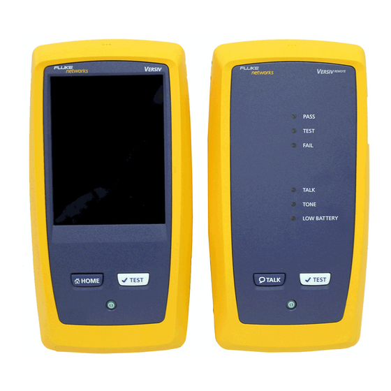
Versiv Cabling Certification Product Family Users Manual Connectors, Keys, and LEDs GPU88.EPS Figure 7. Main Tester Connectors, Keys, and LEDs Connector for a link interface adapter RJ45 jack for communications between the main and remote testers when you do alien crosstalk measurements. See “About the AxTalk Analyzer Kit”... - Page 41 Type A USB port: This USB host port lets you save test results on a USB flash drive, connect the FI-1000 video probe to the tester, and connect a Wi-Fi adapter for access to Fluke Networks cloud services. ...
-
Page 42: Remote Tester Connectors, Keys, And Leds
Versiv Cabling Certification Product Family Users Manual GPU42.EPS Figure 8. Remote Tester Connectors, Keys, and LEDs Connector for a link interface adapter RJ45 jack for communications between the main and remote testers when you do alien crosstalk measurements. See “About the AxTalk Analyzer Kit”... - Page 43 Chapter 2: Certify Twisted Pair Cabling Connectors, Keys, and LEDs TALK LED comes on when the talk function is on ( ). The LED flashes until the main tester accepts the request to talk. TONE LED flashes and the tone generator comes on if you press ...
-
Page 44: About Link Interface Adapters
Versiv Cabling Certification Product Family Users Manual About Link Interface Adapters Link interface adapters let you connect the DSX CableAnalyzer to different types of twisted pair links. Figure 9 shows how to attach and remove adapters. Caution To prevent damage to the cables on the permanent... -
Page 45: How To Prevent Damage To The Permanent Link Adapter Cables
Chapter 2: Certify Twisted Pair Cabling About Link Interface Adapters 5 in (13 cm) minimum GPU108.EPS Figure 10. How to Prevent Damage to the Permanent Link Adapter Cables... -
Page 46: About The Dsx-Pla001 Adapter Modules
Versiv Cabling Certification Product Family Users Manual About the DSX-PLA001 Adapter Modules The DSX-PLA001 Universal Permanent Link Adapter has an interchangeable personality module. The module lets you connect the adapter to different styles of insulation displacement connectors (IDCs). Figure 11 shows how to remove and install a personality module. -
Page 47: How To Change The Personality Module On A Dsx-Pla001 Adapter
Chapter 2: Certify Twisted Pair Cabling About the DSX-PLA001 Adapter Modules GPU164.EPS Figure 11. How to Change the Personality Module on a DSX-PLA001 Adapter... -
Page 48: The Dsx Cableanalyzer Home Screen
Versiv Cabling Certification Product Family Users Manual The DSX CableAnalyzer Home Screen The home screen (Figure 12) shows important test settings. Before you do a test, make sure these settings are correct. GPU110.EPS Figure 12. The Home Screen for the DSX CableAnalyzer ... - Page 49 Chapter 2: Certify Twisted Pair Cabling The DSX CableAnalyzer Home Screen Shows a summary of the test results in the project: : The number of tests that passed. : The number of tests that failed. : The number of tests with an overall marginal result. The test setup panel shows the settings the tester will use ...
-
Page 50: Make Sure Your Tester Is Ready To Certify Cabling
The type of module attached to the main Versiv unit. This icon shows when the tester’s link interface adapter is connected to the adapter on a Versiv remote and the remote is turned on. This icon shows when the talk function is on. To use the... -
Page 51: Set The Reference
and patch cords are in good condition. Make sure the battery is fully charged. Send the modules to a Fluke Networks service center every 12 months for factory calibration. Set the Reference The reference procedure for twisted pair cable sets the baseline for insertion loss, ACR-F, and DC resistance measurements. -
Page 52: Settings For Twisted Pair Tests
Versiv Cabling Certification Product Family Users Manual Connect the main and remote testers together as shown in Figure 13. If you attached Class F/F link interface adapters, make sure you select a Class F or F test limit. See the documentation supplied with the adapters. - Page 53 Chapter 2: Certify Twisted Pair Cabling Settings for Twisted Pair Tests Or to set up a new twisted pair test, tap NEW TEST. If no module is installed, the MODULE screen shows. Tap the correct copper module. On the TEST SETUP screen, tap the panels to change settings for the test.
- Page 54 Versiv Cabling Certification Product Family Users Manual Table 2. Settings for Twisted Pair Tests (continued) This setting shows only when you select a shielded cable Shield Test type. On: The wire map test includes a DC test for shield continuity and AC tests for shield quality. The wire map test fails if the shield is open or the AC test results are unsatisfactory.
- Page 55 Chapter 2: Certify Twisted Pair Cabling Settings for Twisted Pair Tests Table 2. Settings for Twisted Pair Tests (continued) The Outlet Configuration specifies which wire pairs are Outlet tested and which wire numbers the wire map shows for the Configuration pairs.
-
Page 56: Outlet Configurations
Versiv Cabling Certification Product Family Users Manual T568A T568B Crossover 1000BASE-T Crossover Rollover 2 x Two-Pair Crossed Ethernet Ethernet Two-Pair Two-Pair Crossed Token Ring CSU/DSU USOC Two-Pair USOC Single-Pair ATM/TP-PMD ATM/TP-PMD One Pair (1,2) Straight Crossed M12 Two-Pair M12 Two-Pair Crossed GPU85.EPS... -
Page 57: How To Do An Autotest
Figure 15 shows the equipment for Autotests on twisted pair cable. GPU111.EPS Main and remote Versiv units For tests on channels: two with modules installed channel adapters For tests on permanent links:... - Page 58 Versiv Cabling Certification Product Family Users Manual To do an Autotest on twisted pair cable Attach permanent link or channel adapters to the main and remote testers. Make sure that the home screen shows the correct settings for the job.
-
Page 59: Permanent Link Connections
Chapter 2: Certify Twisted Pair Cabling How to Do an Autotest Horizontal cabling Optional consolidation point Patch panel Wall outlet Start permanent permanent link link Tester with Remote with permanent link permanent link adapter adapter GPU97.EPS Figure 16. Permanent Link Connections... -
Page 60: Bad Patch Cord" Message
Versiv Cabling Certification Product Family Users Manual Horizontal cabling Hub or switch Optional consolidation point Patch cord Wall from hub outlet or switch Patch Patch cord panels from PC Start channel channel Tester with Remote with channel adapter channel adapter GPU96.EPS... -
Page 61: How To Certify Patch Cords
To purchase a DSX-PCxxS Patch Cord Adapter Set, contact an authorized Fluke Networks distributor. Twisted Pair Autotest Results The tests listed below apply to twisted pair cabling. Note Some tests are not included in some test limits. -
Page 62: Automatic Diagnostics
Future Versiv software releases may include additional diagnostics. The latest software is available at no charge on the Fluke Networks website. For more information on diagnostics, including video training modules, see the Knowledge Base on the Fluke Networks website. -
Page 63: Pass*/Fail* Results
Chapter 2: Certify Twisted Pair Cabling Twisted Pair Autotest Results GPU192.EPS Figure 18. Examples of Diagnostic Screens for Faults on Twisted Pair PASS*/FAIL* Results A result shows an asterisk when measurements are in the tester’s accuracy uncertainty range (Figure 19) and the asterisk is required by the selected test limit. -
Page 64: Wire Map Tab
Versiv Cabling Certification Product Family Users Manual PASS Tester’s accuracy uncertainty range PASS* PASS* Limit FAIL* FAIL GPU87.EPS Figure 19. PASS* and FAIL* Results WIRE MAP Tab The WIRE MAP tab shows the connections between the ends of the cable under test. The tester compares the connections to the selected Outlet Configuration to get a PASS or FAIL result. -
Page 65: Wire Map Tab
Chapter 2: Certify Twisted Pair Cabling Twisted Pair Autotest Results GPU59.EPS Figure 20. WIRE MAP Tab The overall result for the Autotest. If the result shows an asterisk, See “PASS*/FAIL* Results” on page 49. The result for the wire map test: The wire map does not agree with the outlet configuration selected for the test. -
Page 66: Performance Tab
Versiv Cabling Certification Product Family Users Manual PERFORMANCE Tab The PERFORMANCE tab (Figure 21) shows the overall result for each test that is required by the selected test limit. GPU86.EPS Figure 21. PERFORMANCE Tab The test limit and cable type used for the test. To see all the settings used for the test, tap the panel. -
Page 67: Frequency-Domain Results
Chapter 2: Certify Twisted Pair Cabling Twisted Pair Autotest Results The results are within the limit. The selected test limit does not have a limit for the test, or a dB rule applies. See the Technical Reference Handbook. The results are within the range of accuracy uncertainty for the tester. -
Page 68: Tabular Results Screen For A Frequency-Domain Test
Versiv Cabling Certification Product Family Users Manual GPU104.EPS Figure 22. Tabular Results Screen for a Frequency-Domain Test The location where the tester made the measurements. To switch between results for the main and remote, tap REMOTE or MAIN ( ... - Page 69 Chapter 2: Certify Twisted Pair Cabling Twisted Pair Autotest Results The measured value. The limit specified by the selected test limit. MARGIN is the difference between the measured value and the limit. The value is in a red box if the measurement exceeds the limit.
-
Page 70: Plot Screen For A Frequency-Domain Test
Versiv Cabling Certification Product Family Users Manual GPU71.EPS Figure 23. Plot Screen for a Frequency-Domain Test The location of the measurements. To switch between results for the main and remote, tap REMOTE or MAIN ( Measured values for the wire pairs. - Page 71 Chapter 2: Certify Twisted Pair Cabling Twisted Pair Autotest Results The vertical scale is the measured value in decibels. The horizontal scale is the frequency range in megahertz. To see help for the screen, tap To switch between results for the main unit and the remote, ...
-
Page 72: Diagnostic Tab
10GBASE-T applications. For instructions on how to do alien crosstalk tests, install the AxTalk Analyzer software, which is available on the Fluke Networks website, then see the online help in the software. -
Page 73: Chapter 3 Certify Coaxial Cabling
Chapter 3: Certify Coaxial Cabling The optional DSX-CHA003 coaxial adapters let you use the DSX CableAnalyzer to certify coaxial cabling for network and video applications. Set the Reference for Coaxial Tests To use DSX-CHA003 adapters, you must set the reference for coaxial tests. -
Page 74: Reference Connections For Tests On Coaxial Cabling
Versiv Cabling Certification Product Family Users Manual Notes Set the reference only after the testers are at an ambient temperature between 10 °C and 40 °C (50 °F and 104 °F). The tester will not let you set the reference if the patch cord is longer than 30 cm (12 in). -
Page 75: Settings For Coaxial Tests
Chapter 3: Certify Coaxial Cabling Settings for Coaxial Tests Settings for Coaxial Tests Table 3 gives descriptions of the settings for coaxial tests. To set up a project, which includes the settings in Table 3, cable IDs, and operator names, see Chapter 11. To set up a coaxial test On the home screen, tap the test setup panel. - Page 76 Versiv Cabling Certification Product Family Users Manual Table 3. Settings for Coaxial Tests Setting Description Select DSX-5000 CableAnalyzer. Module Select a cable type that is correct for the type you will Cable Type test. To see a different group of cable types, tap MORE, then tap a group.
-
Page 77: How To Do An Autotest
Chapter 3: Certify Coaxial Cabling How to Do an Autotest How to Do an Autotest Figure 25 shows the equipment for tests on coaxial cabling. Note You can do the HDTDR, length, and resistance tests without a remote tester. See “Tests Without a Remote”... -
Page 78: Equipment For Tests On Coaxial Cabling
Versiv Cabling Certification Product Family Users Manual Or, tap MEASURE to do the length and resistance tests, which do not require a remote tester. Because the tester cannot complete all tests, and the reflection at the end of the cable exceeds the 15% limit for the HDTDR test, the result for an Autotest without a remote is always FAIL. -
Page 79: Examples Of Connections For Tests On Coaxial Cabling
Chapter 3: Certify Coaxial Cabling How to Do an Autotest Data network Disconnect all drop cables DSX-CHA003 DSX-CHA003 COAX ADAPTER COAX ADAPTER IP cameras Surveillance network Router Coaxial segment MoCA MoCA DSX-CHA003 DSX-CHA003 COAX ADAPTER COAX ADAPTER adapter adapter Cable TV Note: Do not do tests through splitters. -
Page 80: Coaxial Autotest Results
Versiv Cabling Certification Product Family Users Manual Coaxial Autotest Results Note Not all test limits include all the tests shown in Figure 27. GPU182.EPS Figure 27. Autotest Results for Coaxial Cabling The test limit and cable type used for the test. -
Page 81: About Splitters
Chapter 3: Certify Coaxial Cabling About Splitters The DIAGNOSTIC tab shows fault information if the test failed, and the HDTDR analyzer button, which you can tap to see the HDTDR plot. The plot helps you find faults on the cable. The HDTDR plot for coaxial cable includes limit lines and a PASS/FAIL result. -
Page 82: Tests Without A Remote
Versiv Cabling Certification Product Family Users Manual Tests Without a Remote You can do the length, resistance, and HDTDR tests without a remote tester. Table 4 describes the effects of a remote on tests. Attach a coaxial adapters to the main tester. - Page 83 Chapter 3: Certify Coaxial Cabling Tests Without a Remote Table 4. Remote Requirements for Coaxial Tests Test Remote Requirements* HDTDR Optional. Without a remote, the plot shows large analyzer reflections at the end of the cabling. Resistance A remote or a terminator is required for a loop resistance measurement.
-
Page 84: Connections For Coaxial Tests Without A Remote
Versiv Cabling Certification Product Family Users Manual DSX-CHA003 COAX ADAPTER For length measurements, disconnect terminators. See Table 4 on page 69. DSX-CHA003 COAX ADAPTER GPU183.EPS Figure 28. Connections for Coaxial Tests Without a Remote... -
Page 85: Continuous Tests
Chapter 3: Certify Coaxial Cabling Continuous Tests Continuous Tests To do the length or resistance test continuously, go to the home screen, tap TOOLS > Single Tests, then tap a test. The length and resistance tests do not compare the results to a test limit. - Page 86 Versiv Cabling Certification Product Family Users Manual...
-
Page 87: Chapter 4 Clean Fiber Endfaces
Chapter 4: Clean Fiber Endfaces Always Clean Endfaces Before Tests When a fiber optic link does not operate correctly, the cause is frequently a dirty endface in a connector. Figure 29 shows examples of dirty endfaces and an endface that has been correctly cleaned and polished. - Page 88 Always clean and inspect the endfaces in fiber connectors before you make connections. Fluke Networks recommends that you use a mechanical device, such as the Fluke Networks IBC OneClick Cleaner, to clean connectors on network equipment. If you do not...
-
Page 89: Equipment To Clean And Inspect Fiber Endfaces
Chapter 4: Clean Fiber Endfaces Always Clean Endfaces Before Tests GPU49.EPS Versiv main unit with CertiFiber Fiber cleaning supplies Pro, OptiFiber Pro, or blank AC adapter with line cord module installed (optional) FI-1000 video probe with USB connector Figure 30. -
Page 90: How To Use A Fluke Networks Ibc Oneclick Cleaner
Versiv Cabling Certification Product Family Users Manual How to Use a Fluke Networks IBC OneClick Cleaner Caution To prevent damage to the device and to connectors and to keep contamination off of endfaces, read all instructions and obey all safety precautions given in the instructions for the device you use to clean connectors. -
Page 91: How To Use The Ibc Oneclick Cleaner
Chapter 4: Clean Fiber Endfaces How to Use a Fluke Networks IBC OneClick Cleaner CLICK! CLICK! CLICK! GPU16.EPS Figure 31. How to Use the IBC OneClick Cleaner... -
Page 92: How To Use Wipes, Swabs, And Solvent
Versiv Cabling Certification Product Family Users Manual How to Use Wipes, Swabs, and Solvent Caution To prevent damage to connectors and to keep contamination off of endfaces: Always discard wipes or swabs after you use them. Do not let solvent dry on an endface. Some solvents leave a residue after they dry. -
Page 93: To Clean The Optical Connectors On The Modules
Chapter 4: Clean Fiber Endfaces How to Use Wipes, Swabs, and Solvent To Clean the Optical Connectors on the Modules To clean the optical connectors on the modules, first use the procedure given under “To Clean Bulkhead Connectors”. If a connector is very dirty or the procedure above does not make it clean, use this procedure: Unscrew the adapter on the connector. - Page 94 Versiv Cabling Certification Product Family Users Manual Notes For APC connectors, hold ferrule against the cleaning area at the same angle (typically 8°) as the ferrule endface. For some connector types, such as VF-45, it is necessary to use a different method to clean the...
-
Page 95: Chapter 5 Inspect Fiber Endfaces
The optional FI-1000 FiberInspector video probe connects to the type A USB port on the Versiv main unit to let you inspect the endfaces in fiber optic connectors. The probe lets you see dirt, scratches, and other defects that can cause unsatisfactory performance or failures in fiber optic networks. -
Page 96: Connectors, Keys, And Leds
Versiv Cabling Certification Product Family Users Manual Connectors, Keys, and LEDs GPU173.EPS Figure 32. Connectors, Keys, and LEDs LCD display with touchscreen. Blank module included with the FI-7000 kit. Keep the module installed to give protection to the module connectors. - Page 97 : Press to go to the home screen. Connector for the ac adapter. RJ45 connector: Lets you connect to a network for access to Fluke Networks cloud services. Removable tip for different types of connectors.
-
Page 98: Settings For Fiberinspector Tests
Versiv Cabling Certification Product Family Users Manual Settings for FiberInspector Tests Table 5 gives descriptions of the settings for FiberInspector tests. To set up a project, which includes the settings in Table 5, cable IDs, and operator names, see Chapter 11. -
Page 99: How To Do The Fiberinspector Test
How to Do the FiberInspector Test How to Do the FiberInspector Test Figure 33 shows the equipment for a FiberInspector test. GPU174.EPS Versiv main unit with CertiFiber Fiber cleaning supplies Pro, OptiFiber Pro, or blank AC adapter with line cord module installed (optional) ... - Page 100 Versiv Cabling Certification Product Family Users Manual To do the FiberInspector test Refer to Figures 34 and 35. Connect the FI-1000 probe to the type A USB port on the side of the tester. Install the correct tip on the probe.
-
Page 101: How To Use The Fi-1000 Probe
Chapter 5: Inspect Fiber Endfaces How to Do the FiberInspector Test GPU168.EPS Figure 34. How to Use the FI-1000 Probe Turn the dial to move the view of the endface. GPU175.EPS ® Figure 35. How to Use the Optional MPO/MTP Inspection Tip... -
Page 102: Fiberinspector Image With Manual Grading Selected
Versiv Cabling Certification Product Family Users Manual Notes The Auto Save function does not operate with the FiberInspector test. Continuous use of the video probe decreases the battery life. To increase the battery life, connect the ac adapter when you use the probe for more than a few minutes. - Page 103 Chapter 5: Inspect Fiber Endfaces How to Do the FiberInspector Test Note To see the buttons for the measurement axes and core scales and to change the magnification of the screen, you must first tap to put the screen in still mode.
-
Page 104: Automatic Analysis Of Scratches And Defects
Versiv Cabling Certification Product Family Users Manual To zoom in and out, use the pinch, reverse-pinch, and double- tap gestures on the touchscreen. See Figure 3 on page 16. Automatic Analysis of Scratches and Defects Note This function operates correctly only with the FI-1000 probe. -
Page 105: Fiberinspector Image With Defect Analysis
Chapter 5: Inspect Fiber Endfaces Automatic Analysis of Scratches and Defects Caution If a defect is possibly a dirt particle, clean the endface and do the inspection again. You must remove all loose particles because they can move into the core when you make connections. GPU167.EPS Figure 37. -
Page 106: Fiber Tests With Two Main Testers
Versiv Cabling Certification Product Family Users Manual These defects are green because they are too far away from the core to cause problems. This scratch is red because it goes through the fiber core. This defect is green because the limit allows a maximum of five defects of that size or smaller in the cladding area. -
Page 107: Chapter 6 Certify Fiber Cabling
The Fluke Networks CertiFiber ® Pro Optical Loss Test Set (OLTS) ™ modules attach to Versiv main and remote units to make rugged, hand-held testers that let you certify, troubleshoot, and document optical fiber cabling installations. The testers include these features: ... -
Page 108: Connectors, Keys, And Leds
Versiv Cabling Certification Product Family Users Manual Connectors, Keys, and LEDs GPU123.EPS Figure 38. Main Tester Connectors, Keys, and LEDs (CFP-QUAD module shown) LCD display with touchscreen Singlemode output port with removable connector adapter and dust cap. This port transmits optical signals for loss and... - Page 109 Type A USB port: This USB host port lets you save test results on a USB flash drive, connect the FI-1000 video probe to the tester, and connect a Wi-Fi adapter for access to Fluke Networks cloud services. ...
- Page 110 Versiv Cabling Certification Product Family Users Manual RJ45 connector: Lets you connect to a network for access to Fluke Networks cloud services. Decal with laser safety information. GPU136.EPS Figure 39. Remote Tester Connectors, Keys, and LEDs (CFP-QUAD module shown)
- Page 111 Chapter 6: Certify Fiber Cabling Connectors, Keys, and LEDs PASS LED comes on when a test passes. TEST LED comes on during a test and when you manually turn on one of the output ports ( FAIL LED comes on when a test fails. TALK LED comes on when the talk function is on.
-
Page 112: How To Remove And Install The Connector Adapters
Versiv Cabling Certification Product Family Users Manual Button to manually control the output ports ( ) and the visual fault locator ( Micro-AB USB port: This USB port lets you connect the tester to a PC so you can install software updates in the tester. -
Page 113: How To Remove And Install The Connector Adapters
Chapter 6: Certify Fiber Cabling How to Remove and Install the Connector Adapters Caution Turn only the collar on the adapter. Do not use tools to remove or install the adapters. Caution Do not touch the photodiode lens. Slot Put the key into the slot before you turn the collar... -
Page 114: The Certifiber Pro Home Screen
Versiv Cabling Certification Product Family Users Manual The CertiFiber Pro Home Screen The home screen (Figure 41) shows important test settings. Before you do a test, make sure these settings are correct. GPU117.EPS Figure 41. The Home Screen for CertiFiber Pro Modules ... - Page 115 Chapter 6: Certify Fiber Cabling The CertiFiber Pro Home Screen Shows a summary of the test results in the project: The number of tests that passed. The number of tests that failed. The test setup panel shows the settings the tester will use when ...
-
Page 116: Requirements For Reliable Fiber Test Results
Versiv Cabling Certification Product Family Users Manual TEST: Tap TEST to do the test shown in the test setup panel. The percentage of the tests in the project that are completed. The tester uses the number of available IDs to calculate this percentage. -
Page 117: About The Reference For Fiber Tests
See Table 6 on page 111. Make sure the battery is fully charged. Send the modules to a Fluke Networks service center every 12 months for factory calibration. About the Reference for Fiber Tests The reference procedure for fiber cable sets a baseline power level for loss measurements. -
Page 118: Good Reference Values
Versiv Cabling Certification Product Family Users Manual The tester requires you to set the reference at these times: When you change the CertiFiber Pro module in the main or remote tester. When you use a different remote tester. -
Page 119: How To See The Reference Values
Chapter 6: Certify Fiber Cabling Requirements for Reliable Fiber Test Results Multimode 50/125 μm fiber: -19.4 dBm to -26.5 dBm Multimode 62.5/125 μm fiber: -17.5 dBm to -23.0 dBm Singlemode fiber: -1.0 dBm to -9.7 dBm If your reference value is outside of the applicable range given above, clean and inspect all connectors then set the reference again. -
Page 120: About The Ef-Trc (Encircled-Flux Test Reference Cords)
Use the EF-TRC cords only with the CertiFiber Pro modules or with sources approved by Fluke Networks for use with the cords. If a source does not have the correct LED and internal fibers, the EF-TRC cords will not make launch conditions that agree with encircled flux standards. -
Page 121: How To Prevent Damage To The Ef-Trc Fiber Cables
Chapter 6: Certify Fiber Cabling Requirements for Reliable Fiber Test Results Use EF-TRCs that have the fiber core dimension (50 µm or 62.5 µm) and type of connectors (SC, ST, LC, or FC) that are the same as the fiber link. Do not use EF-TRCs with hybrid patch cords to connect to links that have other types of connectors. -
Page 122: About Apc Connectors
Versiv Cabling Certification Product Family Users Manual About APC Connectors When you do tests on links with APC (angled physical contact) connectors, use only test reference cords with APC connectors on the ends connected to the link. If you connect non-APC connectors to the link, the connectors will cause large reflections that make loss measurements inaccurate. -
Page 123: Trcs Necessary For Links With Apc Connectors
Chapter 6: Certify Fiber Cabling Requirements for Reliable Fiber Test Results Note Connect only UPC connectors to the tester’s output ports Reference TRC Verification Fiber Link Test *Use the EF-TRCs only with multimode modules. GPU166.EPS Figure 43. TRCs Necessary for Links with APC Connectors... -
Page 124: About Standard Mandrels
Standard mandrels make measurements of multimode power loss more reliable than if you use no mandrels, but the measurements do not comply with the standards for encircled flux. Fluke Networks recommends that you always use only the EF-TRCs with the CertiFiber Pro multimode modules so that your measurements comply with EF standards. - Page 125 Chapter 6: Certify Fiber Cabling Settings for Fiber Tests On the TEST SETUP screen, tap the panels to change settings for the test. See Table 6. On the TEST SETUP screen, tap SAVE when your test setup is completed. On the CHANGE TEST screen, make sure the button next to the test is selected, then tap USE SELECTED.
- Page 126 Versiv Cabling Certification Product Family Users Manual Table 6. Settings for Fiber Tests (continued) Select the correct test limit for the job. To see a different Test Limit group of limits, tap MORE, then tap the name of a group. To make a custom limit, tap Custom in the Limit Groups list.
- Page 127 Chapter 6: Certify Fiber Cabling Settings for Fiber Tests Table 6. Settings for Fiber Tests (continued) The Total Connections and Splices settings are applicable No. of only if the selected test limit uses a calculated limit for loss. Connectors/ Splices Total Connections: Enter the total number of connections that are in each path of the link.
- Page 128 Versiv Cabling Certification Product Family Users Manual GPU140.EPS Figure 44. Screen to Set the Number of Connectors, Splices, and Jumpers Total Connections: Enter the total number of connections that are in each path of the link. Do not adjust the number for the Reference Method you use.
- Page 129 Chapter 6: Certify Fiber Cabling Settings for Fiber Tests Enter the number of splices that are in each path of the Splices link. Enter the number of jumpers you will use in Jumper Reference each fiber path when you set the reference. The dotted lines in the diagram on the screen show you which parts of the link are included in the test results.
- Page 130 Versiv Cabling Certification Product Family Users Manual Connector or connection = 1 connector pair Connector Splice Connectors included in the test results for the 1 Jumper reference Connector method Connector Reference Test connections connections Total Connections: 3 (do not adjust for the Jumpers: 1 reference method)...
-
Page 131: About 1 Jumper Reference Connections
If you do not have the correct connector adapters, see Appendix B for other connections that give 1 jumper results. For descriptions of the 2 and 3 jumper reference connections, see the Versiv Technical Reference Handbook. Caution Most cable manufacturers will give you a... -
Page 132: Autotest In Smart Remote Mode
Versiv Cabling Certification Product Family Users Manual Autotest in Smart Remote Mode Use Smart Remote mode to do tests on dual-fiber cabling. In this mode, the tester measures loss and length on two fibers at two wavelengths. If you turn on the Bi-Directional function, the tester makes measurements in both directions. -
Page 133: Equipment For Autotests In Smart Remote Mode
Chapter 6: Certify Fiber Cabling Autotest in Smart Remote Mode GPU128.EPS Main and remote Versiv units Fiber cleaning supplies with CertiFiber Pro modules FI-1000 video probe with USB installed connector For multimode fiber: two EF-TRC ... -
Page 134: Step 1: Set The Reference In Smart Remote Mode
Versiv Cabling Certification Product Family Users Manual Step 1: Set the Reference in Smart Remote Mode Turn on the tester and remote and let them sit for a minimum of 5 minutes. Let them sit longer if they are above or below ambient temperature. - Page 135 Chapter 6: Certify Fiber Cabling Autotest in Smart Remote Mode Caution Do not disconnect the outputs ( ) after you set the reference. When you use the EF-TRCs, DO NOT use other mandrels. Test reference cord Fiber link Test reference cord...
-
Page 136: Step 2: Measure The Loss Of The Test Reference Cord You Will Add
Versiv Cabling Certification Product Family Users Manual To enter the length of the test reference cords you will add to connect to the link, tap TRC LENGTH on the SET REFERENCE screen. The length you enter does not change the test results. -
Page 137: Step 3: Do An Autotest In Smart Remote Mode
Chapter 6: Certify Fiber Cabling Autotest in Smart Remote Mode Step 3: Do an Autotest in Smart Remote Mode Caution If you disconnected a test reference cord from the output of the tester or remote, you must set the reference again to make sure your measurements are reliable. -
Page 138: Autotest Results For Smart Remote Mode
Versiv Cabling Certification Product Family Users Manual Save the result: If Auto Save is on, the tester uses the next two IDs to save the results for the two fibers. If Auto Save is off, tap SAVE if the test passed or FIX LATER if the test failed. - Page 139 Chapter 6: Certify Fiber Cabling Autotest in Smart Remote Mode GPU118.EPS Figure 48. Result for Smart Remote Mode (Unsaved Bi-Directional Results Shown) The overall result for the Autotest. The fiber IDs and the loss and length measurements for the fibers: The result exceeds the limit.
-
Page 140: Autotest In Loopback Mode
Versiv Cabling Certification Product Family Users Manual To see the results, limits, and margins for a fiber, tap the window. Note The length shown for each fiber is half of the total length of both fibers. The settings the tester used for the test. -
Page 141: Equipment For Autotests In Loopback Mode
Chapter 6: Certify Fiber Cabling Autotest in Loopback Mode GPU129EPS Main Versiv unit with CertiFiber Fiber cleaning supplies Pro module installed FI-1000 video probe with USB For multimode fiber: one EF-TRC connector test reference cord ... -
Page 142: Step 1: Set The Reference In Loopback Mode
Versiv Cabling Certification Product Family Users Manual Step 1: Set the Reference in Loopback Mode Turn on the tester and let it sit for a minimum of 5 minutes. Let it sit longer if it is above or below ambient temperature. - Page 143 Chapter 6: Certify Fiber Cabling Autotest in Loopback Mode Caution Do not disconnect the Fiber output ( ) after you set the reference. When you use the EF-TRCs, DO NOT use other mandrels. Test reference cord Reference TRC Verification Fiber Test *Use the EF-TRCs only with multimode modules.
-
Page 144: Step 2: Measure The Loss Of The Test Reference Cord You Will Add
Versiv Cabling Certification Product Family Users Manual To enter the length of the test reference cord you will add to connect to the fiber under test, tap TRC LENGTH on the SET REFERENCE screen. The length you enter does not change the test results. -
Page 145: Step 3: Do An Autotest In Loopback Mode
Chapter 6: Certify Fiber Cabling Autotest in Loopback Mode Step 3: Do an Autotest in Loopback Mode Caution If you disconnected the test reference cord from the output of the tester, you must set the reference again to make sure your measurements are reliable. -
Page 146: Autotest Results For Loopback Mode
Versiv Cabling Certification Product Family Users Manual Autotest Results for Loopback Mode Figure 51 shows an example of Autotest results for Loopback mode. GPU119.EPS Figure 51. Result for Loopback Mode The overall result for the Autotest. The loss and length measurements for the fiber: The result exceeds the limit. - Page 147 Chapter 6: Certify Fiber Cabling Autotest in Loopback Mode To see the results, limits, and margins for the fiber, tap the window. The settings the tester used for the test. The dashed lines are around the connectors and fiber that are ...
-
Page 148: Autotest In Far End Source Mode
For Far End Source mode, use the EF-TRC cords only with the CertiFiber Pro modules or with sources approved by Fluke Networks for use with the cords. If a source does not have the correct LED and internal fibers, the EF-TRC cords will not make launch conditions that comply with encircled flux standards. -
Page 149: Equipment For Autotests In Far End Source Mode
Chapter 6: Certify Fiber Cabling Autotest in Far End Source Mode GPU130.EPS Main and remote Versiv units Fiber cleaning supplies with CertiFiber Pro modules FI-1000 video probe with USB installed connector For multimode fiber: one EF-TRC ... -
Page 150: Step 1: Set The Reference In Far End Source Mode
Versiv Cabling Certification Product Family Users Manual Step 1: Set the Reference in Far End Source Mode Turn on the tester and source let them sit for a minimum of 5 minutes. Let them sit longer if they are above or below ambient temperature, or if the instructions for the source specify a longer time. - Page 151 Chapter 6: Certify Fiber Cabling Autotest in Far End Source Mode Note When you set the reference, keep the fiber as straight as possible. Turn on the optical source. On the CertiFiber Pro remote module, hold down the button adjacent to the VFL port for 3 seconds to turn on the multimode source.
- Page 152 Versiv Cabling Certification Product Family Users Manual Caution Do not disconnect the output ( ) after you set the reference. When you use the EF-TRCs, DO NOT use other mandrels. EF-TRC* EF-TRC* EF-TRC* Fiber Test reference cord Reference...
-
Page 153: Step 2: Measure The Loss Of The Test Reference Cord You Will Add
Chapter 6: Certify Fiber Cabling Autotest in Far End Source Mode Step 2: Measure the Loss of the Test Reference Cord You Will Add Caution If you disconnected the test reference cord from the output of the tester, you must set the reference again to make sure your measurements are reliable. -
Page 154: Step 3: Do An Autotest In Far End Source Mode
Versiv Cabling Certification Product Family Users Manual Step 3: Do an Autotest in Far End Source Mode Caution If you disconnected the test reference cord from the output of the tester, you must set the reference again to make sure your measurements are reliable. -
Page 155: Autotest Results For Far End Source Mode
Chapter 6: Certify Fiber Cabling Autotest in Far End Source Mode Note To put End 1/End 2 results together in the same record, use LinkWare software to merge the results. Autotest Results for Far End Source Mode Figure 54 shows an example of Autotest results for Far End Source mode. -
Page 156: Result For Far End Source Mode
Versiv Cabling Certification Product Family Users Manual GPU120.EPS Figure 54. Result for Far End Source Mode The overall result for the Autotest. The loss and length measurements for the fiber: The result exceeds the limit. The result is within the limit. -
Page 157: Bi-Directional Tests
Chapter 6: Certify Fiber Cabling Bi-Directional Tests The dashed lines are around the connectors and fiber that are included in the loss and length results. Gray connectors and fibers are not included because you used them to set the reference. - Page 158 Versiv Cabling Certification Product Family Users Manual On the TEST SETUP screen, in the Bi-Directional panel, tap the control to make it show On, then tap SAVE. Do an Autotest. Halfway through the test, the tester tells you to switch the input and output fibers.
-
Page 159: Chapter 7 Use The Otdr
The OptiFiber ® Pro Optical Time Domain Reflectometer (OTDR) ™ module attaches to a Versiv main unit to make a rugged, hand- held tester that lets you locate, identify, and measure reflective and loss events in multimode and singlemode fibers. Typical... -
Page 160: Connectors, Keys, And Leds
Versiv Cabling Certification Product Family Users Manual DataCenter OTDR ™ test gives optimal performance when you do tests on fiber installations that have short links, many connections, and possibly large reflections. FaultMap ™ test lets you make maps of your cable plant, see ... - Page 161 Chapter 7: Use the OTDR Connectors, Keys, and LEDs GPU06.EPS Figure 55. Connectors, Keys, and LEDs (OptiFiber Pro Quad OTDR shown) Micro-AB USB port: This USB port lets you connect the tester to a PC so you can upload test results to the PC and install software updates in the tester.
-
Page 162: How To Remove And Install The Connector Adapters
Type A USB port: This USB host port lets you save test results on a USB flash drive, connect the FI-1000 video probe to the tester, and connect a Wi-Fi adapter for access to Fluke Networks cloud services. Headset jack. -
Page 163: How To Remove And Install The Connector Adapters
Chapter 7: Use the OTDR How to Remove and Install the Connector Adapters Caution Turn only the collar on the adapter. Do not use tools to remove or install the adapters. Put the key into the slot before you turn the collar on the adapter. -
Page 164: The Optifiber Pro Home Screen
Versiv Cabling Certification Product Family Users Manual The OptiFiber Pro Home Screen The home screen (Figure 57) shows important test settings. Before you do a test, make sure these settings are correct. GPU02.EPS Figure 57. The Home Screen PROJECT: The project contains the settings for a job and helps ... - Page 165 Chapter 7: Use the OTDR The OptiFiber Pro Home Screen : The number of tests that passed. : The number of tests that failed. The test setup panel shows the settings the tester will use when you tap TEST or press . To change these settings, tap the panel, select the test on the CHANGE TEST screen, tap EDIT, select different settings on the TEST SETUP screen, then tap SAVE.
-
Page 166: Settings For Otdr Tests
Versiv Cabling Certification Product Family Users Manual The percentage of the tests in the project that are completed. The tester uses the number of available IDs and the tests you selected on the CABLE ID SETUP screen to calculate this percentage. - Page 167 Chapter 7: Use the OTDR Settings for OTDR Tests Table 7. Settings for OTDR Tests Select the OTDR module you will use. Module To select a different module, tap the Module panel on the TEST SETUP screen, then tap a module. When you turn on the tester, the Test Type shows the test Test Type that was last selected.
- Page 168 Versiv Cabling Certification Product Family Users Manual Table 7. Settings for OTDR Tests (continued) FaultMap: The FaultMap test can show connections that Test Type do not show on the OTDR EventMap and connections that (cont.) are poor because they have high reflectance. See “The FaultMap Test”...
- Page 169 Chapter 7: Use the OTDR Settings for OTDR Tests Table 7. Settings for OTDR Tests (continued) IR: The tester uses the index of refraction to calculate the Fiber Type optical length of the fiber. Each fiber type includes the Settings value specified by the manufacturer.
-
Page 170: About Launch And Tail Cords
Fluke Networks recommends that you use launch and tail cords. You should also use the launch/tail cord compensation function to remove the lengths of these fibers from the OTDR measurements. - Page 171 Chapter 7: Use the OTDR About Launch and Tail Cords How to set up the launch compensation function Select launch and tail cords that have the same type of fiber as the fiber you will test. On the home screen, tap the test setup panel. On the CHANGE TEST screen, select an OTDR test to change, then tap EDIT.
-
Page 172: How To Prevent Damage To The Launch Cord Connectors
Versiv Cabling Certification Product Family Users Manual How to Prevent Damage to the Launch Cord Connectors When you do not use a launch cord, keep the connectors attached to the case or inside the case. See Figure 58. Cords in a zippered case ... -
Page 173: Otdr Port Connection Quality
Clean the OTDR port and the fiber connector. Use a video probe to inspect the endfaces in the port and fiber connector for scratches and other damage. If an endface on the tester shows damage, contact Fluke Networks for service information. -
Page 174: The Otdr Port Connection Quality Gauge And Progress Screen
Versiv Cabling Certification Product Family Users Manual If the gauge stays outside the Good range, remove the adapter from the module and inspect the adapter for damage. Make sure that the white plastic ring inside the center tube shows no damage. -
Page 175: How To Do An Otdr Test
Tap TEST or press . Note The tester shows a warning if there is an optical signal on the fiber. GPU31.EPS Versiv unit with OTDR module FI-1000 video probe with USB installed connector Launch and tail cords (match the... -
Page 176: Otdr Connected With A Launch Cord
Versiv Cabling Certification Product Family Users Manual Fiber link Launch cord Versiv unit with OTDR module GPU03.EPS Figure 62. OTDR Connected with a Launch Cord... -
Page 177: Otdr Connected With Launch And Tail Cords
Chapter 7: Use the OTDR How to Do an OTDR Test Tail cord Fiber link Launch cord Versiv unit with OTDR module GPU04.EPS Figure 63. OTDR Connected with Launch and Tail Cords... -
Page 178: Otdr Connected To A Spool Of Fiber
Versiv Cabling Certification Product Family Users Manual Spool of fiber Mechanical splice Versiv unit with OTDR module GPU05.EPS Figure 64. OTDR Connected to a Spool of Fiber... -
Page 179: Otdr Results
Chapter 7: Use the OTDR OTDR Results OTDR Results Notes The tester shows measurements with “>” or “<“ when the actual value is possibly more or less than the value shown. For example, this can occur for hidden events or for measurements that are out of the range of the tester. -
Page 180: Eventmap Example 1
Versiv Cabling Certification Product Family Users Manual GPU11.EPS Figure 65. EventMap Example 1 The ID for the results. If Auto Save is off, Result not saved shows. The end of the fiber. The length of the fiber segment between two events. - Page 181 Chapter 7: Use the OTDR OTDR Results : The arrow icon shows when there are more events that do not show on the screen. To see the events, tap the icon or scroll the map. When more than one button shows at the bottom of the ...
-
Page 182: Eventmap Example 2
Versiv Cabling Certification Product Family Users Manual Overall Loss: The loss of the cabling. This does not include the OTDR connection and the loss of the last event. If Launch Compensation is on, the overall loss includes the launch and tail connectors, but not the launch and tail fibers. -
Page 183: Event Table
Chapter 7: Use the OTDR OTDR Results Length of the tail cord (top) and launch cord (bottom). A loss event, such as a splice or bend: : Measurements for the event are all within the test limits. : One or more measurements for the event exceeds the limit. : The event is hidden by a previous event. -
Page 184: Event Table
Versiv Cabling Certification Product Family Users Manual Note The OTDR Port and End events always show N/A for loss because backscatter measurements are not available on both sides of those events. to see help for this screen. OVERALL: Tap this button to see overall measurements of ... - Page 185 Chapter 7: Use the OTDR OTDR Results If the tester made measurements at two wavelengths, tap the arrow buttons to see results for the other wavelength. Possibly, some events show only at one wavelength. : The measurement is within the limit. ...
-
Page 186: Otdr Trace
Versiv Cabling Certification Product Family Users Manual OTDR Trace To see the OTDR trace, tap TRACE on the OTDR results screen. Figure 68 shows an example of an OTDR trace. GPU14.EPS Figure 68. OTDR Trace The decibel scale shows the level of backscatter. The tester sets ... - Page 187 Chapter 7: Use the OTDR OTDR Results When the cursor is on an event, this area shows the event type. The text is green if the event passed, red if the event failed, or black is there is no limit for measurements. The event type does not show after you tap MARK to use the measurement cursor.
-
Page 188: The Faultmap Test
Versiv Cabling Certification Product Family Users Manual The FaultMap Test The FaultMap test helps you record the connections in a fiber link and identify bad connections. It can show short patch cords and find connections that have high reflectance. The FaultMap test... -
Page 189: How To Do The Faultmap Test
Chapter 7: Use the OTDR The FaultMap Test How to Do the FaultMap Test Notes The FaultMap test does not use the launch compensation settings. The FaultMap test uses the wavelength that gives the best results. Figure 69 shows the equipment for the FaultMap test. Clean and inspect the connectors on the launch and tail cords or patch cords and the link to be tested. -
Page 190: Equipment For Faultmap Tests
Versiv Cabling Certification Product Family Users Manual GPU39.EPS Versiv unit with OTDR module FI-1000 video probe with USB installed connector Launch and tail cords or patch Fiber cleaning supplies cords (match the fiber to be ... -
Page 191: Faultmap Test Connections
Chapter 7: Use the OTDR The FaultMap Test Tail cord or patch cord (optional) Launch cord or patch cord (optional) Versiv unit with OTDR module GPU41.EPS Figure 70. FaultMap Test Connections... -
Page 192: Faultmap Screen
Versiv Cabling Certification Product Family Users Manual FaultMap Screen GPU15.EPS Figure 71. FaultMap Screen Note The FaultMap test does not use the launch compensation settings. The results show the launch and tail cords and their connectors in the same colors as other cords and connectors. - Page 193 Chapter 7: Use the OTDR The FaultMap Test : An event that has a reflectance larger than -35 dB. It is possibly a connector that is dirty, poorly polished, scratched, cracked, misaligned, unseated, worn, or the wrong type. : The arrow icon shows when there are more events that do not show on the screen.
-
Page 194: The Smartloop Test
Versiv Cabling Certification Product Family Users Manual The SmartLoop Test The SmartLoop test lets you connect the far ends of the two fibers in a link and do one OTDR test to get separate results for each fiber. You use a launch cord to connect the fibers together at the far end of the link. -
Page 195: How To Do An Auto Smartloop Test
Chapter 7: Use the OTDR The SmartLoop Test How To Do an Auto SmartLoop Test On the home screen, tap the test setup panel. On the CHANGE TEST screen, tap the button next to the Auto SmartLoop test, then tap USE SELECTED. If an Auto SmartLoop test is not available, tap NEW TEST to add one to the project. -
Page 196: Smartloop Launch Compensation Connections
Versiv Cabling Certification Product Family Users Manual Loopback cord Tail cord Versiv unit with Launch cord OTDR module GPU170.EPS Figure 73. SmartLoop Launch Compensation Connections... -
Page 197: Smartloop Test Connections
(Tail Cord for Fiber A and Launch Cord for Fiber B) OTDR Port event for End event for Fiber A Fiber B Fiber link Fiber A Fiber B Tail cord Launch cord Versiv unit with OTDR module GPU171.EPS Figure 74. SmartLoop Test Connections... -
Page 198: Smartloop Results
Versiv Cabling Certification Product Family Users Manual SmartLoop Results The tester shows the SmartLoop results on two sets of EventMap, TABLE, and TRACE screens, one for each fiber in the link. See Figure 75. GPU172.EPS Figure 75. EventMap from a SmartLoop Test The purple fiber is the loopback cord. -
Page 199: Bi-Directional Smartloop Tests
Chapter 7: Use the OTDR The SmartLoop Test To switch between results for fibers A and B, tap on the EventMap screen. If you did a bi-directional SmartLoop test, touch for 3 seconds to see a summary of the results from ends 1 and 2 on fibers A and B. - Page 200 Versiv Cabling Certification Product Family Users Manual Make the connections for End 1 as shown in Figure 76. Note To decrease the wear on the OTDR connector and help keep it clean, use the short (30 cm, 12 in) patch cord provided to connect the OTDR to the launch and tail cords for bi-directional SmartLoop tests.
-
Page 201: Smartloop Test Connections For A Bi-Directional Test
Chapter 7: Use the OTDR The SmartLoop Test Loopback cord Loopback cord (Tail Cord for Fiber A (Tail Cord for Fiber B and Launch Cord for and Launch Cord for Fiber B) Fiber A) OTDR Port event End event End event OTDR Port event for Fiber B for Fiber A... - Page 202 Versiv Cabling Certification Product Family Users Manual...
-
Page 203: Chapter 8 Use The Visual Fault Locator
Chapter 8: Use the Visual Fault Locator Visual Fault Locator Applications The CertiFiber Pro and OptiFiber Pro modules include a visual fault locator that sends a red light down the fiber. The red light shows at the end of the fiber and at breaks, cracks, and sharp bends along the fiber. -
Page 204: How To Use The Vfl
Versiv Cabling Certification Product Family Users Manual How to Use the VFL Figure 77 shows the equipment for tests with the visual fault locator. GPU137.EPS Versiv main unit with CertiFiber FI-1000 video probe with USB Pro or OptiFiber Pro module... - Page 205 Chapter 8: Use the Visual Fault Locator How to Use the VFL To use the visual fault locator Note You can connect the visual fault locator to connectors that have 2.5 mm ferrules (SC, ST, or FC). To connect to other ferrule sizes, use a test reference cord with the correct connector at one end and a SC, ST, or FC connector at the tester end.
-
Page 206: How To Use The Visual Fault Locator
Versiv Cabling Certification Product Family Users Manual Verify continuity and identify fibers VFL connector VFL button Find microbends and broken fibers Find connectors that have broken fibers inside 1 Press the VFL button: VFL is on (CW, continuous wave). Find splices that have... -
Page 207: Chapter 9 Monitor Optical Power
Chapter 9: Monitor Optical Power You can use the CertiFiber Pro main tester to monitor and save measurements of optical power and loss, and you can use the main or remote tester and as an optical power source. You can use the main tester’s power or loss meter and its light source at the same time. -
Page 208: Equipment For Power Meter Measurements
Versiv Cabling Certification Product Family Users Manual GPU137EPS Versiv main unit with CertiFiber FI-1000 video probe with USB Pro module installed connector One test reference cord AC adapter with line cords (optional) Fiber cleaning supplies Figure 79. -
Page 209: Connections To Monitor Power And Loss
Chapter 9: Monitor Optical Power How to Monitor Power and Loss Optical network Power at the interface card or end of a link optical power source Power from an optical source GPU138.EPS Figure 80. Connections to Monitor Power and Loss To monitor loss On the POWER METER / LIGHT SOURCE screen, tap REF to use the present power level as a reference. -
Page 210: Power Meter Measurements And Controls
Versiv Cabling Certification Product Family Users Manual Power measurements Loss measurements GPU126.EPS Figure 81. Power Meter Measurements and Controls The meters show the power levels received on the input port. This control shows when the meters measure absolute power. -
Page 211: How To Control The Light Source
Chapter 9: Monitor Optical Power How to Control the Light Source To select a wavelength for the power meter, tap . Use the Auto CertiFiber Pro and Auto SimpliFiber Pro modes only with a CertiFiber Pro or SimpliFiber Pro source. In these modes, the tester reads the wavelength identifiers transmitted by the source to know when to measure power at each wavelength. -
Page 212: Use The Display To Control The Main Tester's Light Source
Versiv Cabling Certification Product Family Users Manual Use the Display to Control the Main Tester’s Light Source Clean and inspect all connectors you will use. Connect the tester’s output port to the power meter. If your tester has a CertiFiber Pro Quad module installed, make sure you connect the fiber to the correct output port. -
Page 213: Light Source Controls For The Main Tester
Chapter 9: Monitor Optical Power How to Control the Light Source GPU127.EPS Figure 82. Light Source Controls for the Main Tester Use the buttons to control the output port when you use the main tester as a light source: ... - Page 214 Versiv Cabling Certification Product Family Users Manual...
-
Page 215: Chapter 10 Manage Test Results
Chapter 10: Manage Test Results View Saved Results On the home screen, tap the RESULTS icon. The RESULTS screen shows the results in the active project. See Figure 83. To view results saved on a USB flash drive, connect the drive, then tap RESULTS, TRANSFER, USB Flash Drive, Import. -
Page 216: Results Screen
Versiv Cabling Certification Product Family Users Manual HEJ24.EPS Figure 83. RESULTS Screen The name of the active project. : The number of results that passed. This includes individual results for each ID and tests that have an result. - Page 217 Chapter 10: Manage Test Results View Saved Results accuracy uncertainty for the tester. See “PASS*/FAIL* Results” on page 49. Note These numbers show the total number of results that passed and failed in the IDs saved. So, the numbers can be more than the number of IDs saved.
-
Page 218: How To Add A Result To A Saved Result
These icons show when you connect the tester to a network to use Fluke Networks cloud services (see Chapter 12): The tester is connected to a wireless network. The tester is connected to a wired network. -
Page 219: How To Replace A Saved Result That Failed
Chapter 10: Manage Test Results How to Replace a Saved Result that Failed If the settings do not agree, the tester shows a warning. To add results for a different End setting for power meter and FiberInspector tests Do the test, then tap SAVE. ... -
Page 220: Delete, Rename, And Move Results
Versiv Cabling Certification Product Family Users Manual To replace a result with a result that uses different test settings Turn off Auto Save. Make sure that the home screen shows the project that contains the result you want to replace. -
Page 221: Manage Results On A Flash Drive
You can lose a USB flash drive, cause damage to it, or accidentally erase the contents of the drive. Thus, Fluke Networks recommends that you save no more than one day of test results on a flash drive. Note The tester reads only USB drives that use the FAT format. -
Page 222: Upload Results To A Pc
Versiv Cabling Certification Product Family Users Manual On the home screen, tap the RESULTS icon, then tap TRANSFER. On the TRANSFER RESULTS screen, tap USB Flash Drive, then tap a function: Export: On the EXPORT RESULTS screen, select New or All, select the project that contains the results you want to export to the flash drive, then tap EXPORT. -
Page 223: How To Connect The Tester To A Pc
Chapter 10: Manage Test Results Upload Results to a PC Or connect a USB flash drive to the PC. On the LinkWare PC toolbar, click , then select a product, or select Test Files (.tst) to upload from a flash drive. In the Import dialog box in LinkWare PC, select options for the location and the number of results to import. -
Page 224: View The Memory Status
Versiv Cabling Certification Product Family Users Manual View the Memory Status To see the memory status On the home screen, tap the TOOLS icon, then tap Memory Status. The MEMORY STATUS screen shows these values: The percentage of memory available ... -
Page 225: Chapter 11 Use Projects
It is not necessary to install a module to set up a project for the module. The tester keeps all settings in the main Versiv unit. To manage projects in the cloud, use the LinkWare Live web application. See Chapter 12. -
Page 226: Set Up A Project
Versiv Cabling Certification Product Family Users Manual Set Up a Project Refer to the PROJECT screen in Figure 85 on page 213. On the home screen, tap the PROJECT panel, tap CHANGE PROJECT, then tap NEW PROJECT. On the NEW PROJECT screen, enter a name for the project, then tap DONE. -
Page 227: Project Screen
Chapter 11: Use Projects The PROJECT Screen GPU08.EPS Figure 85. PROJECT Screen : The number of DSX CableAnalyzer results that have PASS* results. PASS* results have measurements within the range of accuracy uncertainty for the tester. See “PASS*/FAIL* Results” on page 49. - Page 228 Versiv Cabling Certification Product Family Users Manual To use a different project, tap CHANGE PROJECT, then tap a project. To make a new project, tap CHANGE PROJECT, then tap NEW PROJECT. TRANSFER lets you export or import projects to or from a flash ...
-
Page 229: The Cable Id Setup Screen
Chapter 11: Use Projects The CABLE ID SETUP Screen The CABLE ID SETUP Screen To see the CABLE ID SETUP screen, tap the PROJECT panel on the home screen, then tap NEW ID SET on the PROJECT screen. See Figure 86 on page 216. Each project can have up to 5000 IDs. - Page 230 Versiv Cabling Certification Product Family Users Manual If your project has both a Next ID set and sets with first and last IDs, the % Tested value includes tests you saved with Next ID. For example, if you have one Next ID set and one set with 10 IDs, and you save 10 results with next IDs, the % Tested shows 50% (10 saved results divided by 20 IDs).
- Page 231 Chapter 11: Use Projects About Next ID Sets Note The tester does not increment symbols or accented characters. When you use an ID set that does not have a Last ID, the set under IDs Untested on the CHANGE ID screen shows only the next ID.
-
Page 232: Manage Projects On A Flash Drive
You can lose a USB flash drive, cause damage to it, or accidentally erase the contents of the drive. Thus, Fluke Networks recommends that you save no more than one day of test results on a flash drive. Note The tester reads only USB drives that use the FAT format. -
Page 233: Copy Project Settings To Other Testers
Copy Project Settings to Other Testers Copy Project Settings to Other Testers To copy the settings in a project to other Versiv units, use the Read Project Setups and Write Project Setups utilities in LinkWare PC software. You can use LinkWare PC to read project settings... - Page 234 Versiv Cabling Certification Product Family Users Manual...
-
Page 235: Chapter 12 Sync Projects With Linkware ™ Live
If you already have a Fluke Networks ID, enter your email address and password on the LinkWare Live Sign In page. If you do not have a Fluke Networks ID, click New user? Sign up now!. Enter the information for your account, then click GET STARTED. -
Page 236: How To See The Tester's Mac Address
Versiv Cabling Certification Product Family Users Manual How to See the Tester’s MAC Address Some networks require users to register their device’s MAC address before they can connect to the network. There are two MAC addresses: one for the wired port and one for the Wi-Fi adapter. -
Page 237: Use Linkware Live Through A Wi-Fi Ethernet Network
Use LinkWare Live Through a Wi-Fi Ethernet Network On the SIGN IN screen, enter the ID and password for your LinkWare Live or Fluke Networks web account, then tap SIGN If you use other people’s LinkWare Live accounts, the ORGANIZATION screen shows. Tap the organization you want to use. - Page 238 LinkWare Live panel. On the SIGN IN screen, enter the ID and password for your LinkWare Live or Fluke Networks web account, then tap SIGN Enter a user name and password for the network, if necessary. If you use other people’s LinkWare Live accounts, the ORGANIZATION screen shows.
-
Page 239: Sync Projects Screen
™ Chapter 12: Sync Projects with LinkWare Live Use LinkWare Live Through a Wi-Fi Ethernet Network GPU190.EPS Figure 87. SYNC PROJECTS Screen If you select Assigned to me only, you will see only projects that are assigned to you in the project settings in LinkWare Live. -
Page 240: Change The Network Settings
Versiv Cabling Certification Product Family Users Manual Change the Network Settings It is not usually necessary to change the wired or Wi-Fi network settings before you try to make a connection. But for example if you must use static addressing, you can get to the settings on the NETWORK screen. - Page 241 ™ Chapter 12: Sync Projects with LinkWare Live Sign Your Tester Out of LinkWare Live Table 8. Settings for the Wi-Fi Connection Setting Description Most networks use DHCP. Address DHCP address SSID: The tester does a scan for wireless networks and settings shows a list of available networks.
-
Page 242: Get Started With Linkware Live
Sign In to LinkWare Live from a Desktop or Mobile Device Go to https://www.linkwarelive.com/signin. Enter your Fluke Networks user name and password, then click SIGN IN. For more information about how to use LinkWare Live, click SUPPORT on the LinkWare Live web page. -
Page 243: Import Projects From Linkware Live Into Linkware Pc
Use the USB cable supplied to connect the Micro-AB USB port on the tester to a type A USB port on the PC. On the LinkWare PC toolbar, click Sign in to your Fluke Networks web account, then use the LinkWare PC dialog boxes to select and import projects. - Page 244 Versiv Cabling Certification Product Family Users Manual...
-
Page 245: Chapter 13 Maintenance
Use only service centers that are approved by Fluke Networks. Caution If you replace electrical parts yourself, the tester will possibly not have the correct calibration and can give incorrect test results. -
Page 246: Verify Operation
Versiv Cabling Certification Product Family Users Manual Verify Operation The tester does a self test when you turn it on. If the tester shows an error or does not turn on, refer to “If the Tester Does Not Operate as Usual” on page 240. -
Page 247: Traceable Calibration Period
Traceable Calibration Period Traceable Calibration Period To make sure that the modules operate within the published specifications for accuracy, have them calibrated at a Fluke Networks authorized service center every 12 months. See Information About the Tester To see information about your tester and attached modules and... -
Page 248: Use A Pc To Update The Software
TOOLS icon on the home screen, tap Version Information, then make sure the Versiv main unit and the module show the correct version. Do steps 3 through 5 again for the remote. On a remote... -
Page 249: How To Connect The Tester To A Pc
Chapter 13: Maintenance Update the Software AC adapter Type A USB port Micro-AB USB port GPU46.EPS Figure 88. How to Connect the Tester to a PC... -
Page 250: Use An Updated Main Tester To Update Other Testers
On the SIGN IN screen, enter the ID and password for your LinkWare Live or Fluke Networks web account, then tap SIGN If a Versiv software update is available, the tester shows a message. Tap YES to install new software in your tester. -
Page 251: Update The Software In A Module
Update the Software in a Module To update the software in a module, attach it to a main or remote Versiv unit that has the latest software. The tester automatically installs the software in the module. Extend the Life of the Battery Do not frequently let the battery discharge completely. -
Page 252: How To Connect Units Together To Update The Software
Versiv Cabling Certification Product Family Users Manual adapter adapter Updated main unit Remote Type A USB port Micro-AB USB port adapter adapter Updated main unit Main unit Type A USB port Micro-AB USB port HGD116.EPS Figure 89. How to Connect Units Together to Update the Software... -
Page 253: Remove The Battery
Figure 90. How to Remove the Battery Calibration To make sure that the modules operate within the published specifications for accuracy, have them calibrated at a Fluke Networks authorized service center every 12 months. To get information on factory calibration, contact an authorized Fluke Networks Service Center. -
Page 254: If The Tester Does Not Operate As Usual
If the condition continues, contact Fluke Networks for assistance, or search the Fluke Networks Knowledge Base for a solution. If you contact Fluke Networks, have available the serial number, software and hardware versions, and calibration date for the tester, if possible. -
Page 255: Options And Accessories
Chapter 13: Maintenance Options and Accessories Options and Accessories For a complete list of options and accessories go to the Fluke Networks website at www.flukenetworks.com. To order options and accessories, contact an authorized Fluke Networks distributor. Regulatory Information This equipment generates, uses, and can radiate radio frequency energy, and, if not installed and used in accordance with the manual, may cause interference to radio communications. - Page 256 Versiv Cabling Certification Product Family Users Manual...
-
Page 257: Appendix A: Reference Method Names
Appendix A: Reference Method Names Industry standards use different names for the three reference methods. Tables A-1 and A-2 show the names used in this manual and by four common standards. Table A-1. Reference Method Names fore TIA/EIA Standards Link End Connections Method Included in Loss... - Page 258 Versiv Cabling Certification Product Family Users Manual...
-
Page 259: Appendix B: Modified 1 Jumper Reference Method
Appendix B: Modified 1 Jumper Reference Method This Appendix shows modified reference and test connections that give 1 jumper results. Use these connections if you need 1 jumper results, but do not have the correct connector adapters to connect the CertiFiber Pro modules’ output ports to the link. This method lets you keep the test reference cords connected to the module’s output ports when you connect the modules to the link. - Page 260 Versiv Cabling Certification Product Family Users Manual Caution Do not disconnect the outputs ( ) after you set the reference. Mandrel* Short MT-RJ (no pins) to MT-RJ (pinned) test reference cord (0.3 m or less. Mandrel* Reference Fiber Link Test *Use mandrels only with multimode modules.
Need help?
Do you have a question about the Versiv and is the answer not in the manual?
Questions and answers