
Related Manuals for Fluke Fiber Viewer FT120


Summary of Contents for Fluke Fiber Viewer FT120
- Page 1 Model T100, Voltage/Continuity November 2006 © 2006 Fluke Corporation. All rights reserved. Printed in China T120, T140, Tester Users Manual ®...
- Page 2 Fluke T100/120/140 Introduction References marked on instru- ment or in instruction manual: Warning of a potential danger, comply with instruction manual. Reference. Please use utmost attention. Caution! Dangerous voltage. Danger of electrical shock. Continuous double or reinforced insulation complies with category II IEC 61140.
-
Page 3: Introduction / Scope Of Supply
The voltage testers FLUKE T100/ T120/ T140 characterised by the following features: • Constructed in compliance with DIN EN 61243-3, DIN VDE 0682 Part 401 (previously... -
Page 4: Safety Measures
Fluke T100/120/140 Safety Measures Safety Measures The instruments FLUKE T100/T120/T140 have been constructed and verified in compliance with the safety measures for voltage testers and have left the factory in safe and perfect condition. In order to avoid electrical shock, the valid... -
Page 5: Appropriate Usage
When modifying or changing the instru- ment, the operational safety is no longer ensured. The instrument may only be opened by an authorised service technician, e.g. for fuse replacement. Fluke T100/120/140 Safety Measures... -
Page 6: Control Elements And Connections
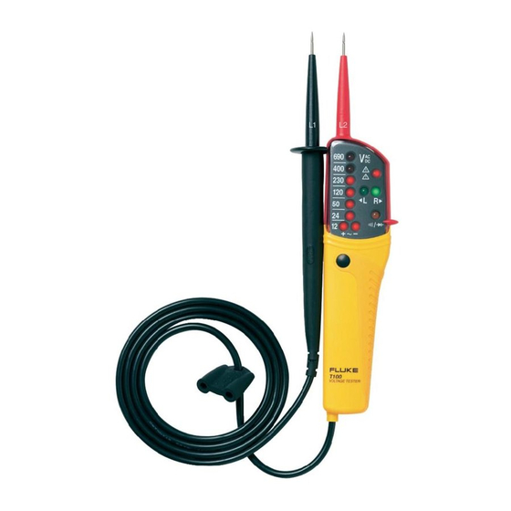
LED for single-pole phase test LED for left/right rotary field LED for continuity Polarity indication LCD for voltage display (only FLUKE T120 and T140) Button on rear side - for measurement point lightning (Also resistance measure- ment and RCD Trip Test in T140VDE) -
Page 7: Voltage Test
From a voltage of < 12V the voltage tester switches on automatically. The voltage is indicated by LED (4) and for models FLUKE T120 and T140 also with a digital LCD (9). For AC voltages the ”+” and ”-” LEDs are il- luminated. -
Page 8: Single-Pole Phase Test
Fluke T100/120/140 Users Manual Single-Pole Phase Test • To carry out single-pole phase tests ouch the Accessible electrode (11) and connect instru- ment test probes to unknown contact. • The single-pole phase test starts at an AC voltage of approx. 100V (pole > 100V AC). - Page 9 • Check that UUT is not live by carrying out a double-pole voltage test. • Connect both test probes with UUT. A signal sound is audible for continuity and the LED for continuity Rx/1 is illuminated. Fluke T100/120/140 Users Manual...
- Page 10 Fluke T100/120/140 Users Manual Rotary Field Indication The voltage testers are equipped with a double- pole rotary field indicator. The safety measures have to be met The rotary phase indication is always active. The symbols R However, the rotary direction can only be deter- mined within a three-phase system.
-
Page 11: Maintenance
The measurement point illumination is active during approx. 45 seconds (only T140). Maintenance When using FLUKE T100/T120/T140 testers in compliance with the instruction manual, no par- ticular maintenance is required. If functional er- rors occur during normal operation, stop using it and contact your nearest authorized service center. - Page 12 Fluke T100/120/140 Maintenance OPEN When batteries have leaked, the device must not be used any longer. Before you can use it again, it must be checked by our customer service. Never try to dismantle a battery cell! The electrolyte in the cell is extremely alkaline and electroconductive.
-
Page 13: Technical Data
Protection degree ...IP65 Safety complying to...DIN EN/IEC 61243-3, Weight ...180g (incl. batteries) Dimensions (HxWxD) ...240 x 56 x 24mm * only T120,T140, T140VDE / ** only T140,T140VDE Fluke T100/120/140 Technical Data 400, 690V 0682, Part 401 0...19991/11 digits) at 20 °C... - Page 14 Fluke T100/120/140 Warranty LIMITED WARRANTY & LIMITATION OF LIABILITY This Fluke product will be free from defects in material and workmanship for one year from the- date of purchase. This warranty does not cover fuses, disposable batteries, or damage fromacci- dent, neglect, misuse, alteration, contamination, or abnormal conditions of operation orhandling.
Need help?
Do you have a question about the Fiber Viewer FT120 and is the answer not in the manual?
Questions and answers