Motorola ROKR E2 Service Manual
Digital wireless telephone
Hide thumbs
Also See for ROKR E2:
- Instruction manual (108 pages) ,
- User manual (95 pages) ,
- Manual (48 pages)

Related Manuals for Motorola ROKR E2


Summary of Contents for Motorola ROKR E2
- Page 1 Level 1 and 2 Service Manual 6809497A99-O ROKR E2 Digital Wireless Telephone GSM 900/1800/1900 or GSM 850/1800/1900 MHz GPRS...
-
Page 3: Table Of Contents
1 and 2 ROKR E2 6809497A99-O Level 1 and 2 Service Manual Contents Contents Contents Contents ................. 3 Introduction . - Page 4 Contents ROKR E2 March 27, 2006 6809497A99-O...
-
Page 5: Introduction
Available on a contract basis, Motorola Inc. offers comprehensive maintenance and installation programs which enable customers to meet requirements for reliable, continuous communications. To learn more about the wide range of Motorola service programs, contact your local Motorola products representative or the nearest Customer Service Manager. Product Identification Motorola products are identified by the model number on the housing. -
Page 6: Computer Program Copyrights
The Motorola products described in this manual may include Motorola computer programs stored in semiconductor memories or other media that are copyrighted with all rights reserved worldwide to Motorola. Laws in the United States and other countries preserve for Motorola, Inc. certain exclusive rights to the copyrighted... -
Page 7: Warranty Service Policy
Customer’s original units will be repaired but not refurbished as standard. Appointed Motorola Service Hubs will perform warranty and non-warranty field service for level 2 (assemblies) and level 3 (limited PCB component). The Motorola High Technology Centers will perform level 4 (full component) repairs. -
Page 8: Parts Replacement
When ordering crystals or channel elements, specify the Motorola part number, description, crystal frequency, and operating frequency desired. When the Motorola part number of a component is not known, use the product model number or other related major assembly along with a description of the related major assembly and of the component in question. -
Page 9: Specifications
Level 1 and 2 Service Manual Specifications Specifications General Function Specification 824-849 MHz Tx Frequency Range GSM 850 869-894 MHz Rx 880-915 MHz Tx (with EGSM) Frequency Range GSM 900 925-960 MHZ Rx 1710-1785 MHz Tx Frequency Range DCS 1800 1805-1880 MHz Rx 1850-1910 MHz Tx Frequency Range PCS 1900... - Page 10 Specifications ROKR E2 Receiver Specification Time to Camp Approximately 5-10 seconds Speech Coding Function Specification Regular pulse excitation / linear predictive coding Speech Coding Type with long term prediction (RPE LPC with LTP) Bit Rate 13.0 kbps Frame Duration 20 ms...
-
Page 11: Product Overview
Level 1 and 2 Service Manual Product Overview Product Overview Motorola ROKR E2 mobile telephones feature global system for mobile communications (GSM) air interface, general packet radio service (GPRS) transport technology, and wireless application protocol (WAP) Internet browser. The mobile... - Page 12 Product Overview ROKR E2 • Tri-coder/decoder (CODEC) that allows full rate, half rate, and enhanced full rate modes of transmission • Supports MP3, AAC, WMA, RA, WAV, MIDI, AMR-NB/-WB audio • Expandable to over 1GB with removable memory (SD/MMC card) •...
- Page 13 Level 1 and 2 Service Manual Product Overview ➧ If the user receives a call while in browser mode, the browser will pause and allow the user to resume after completing the call. Simplified Text Entry iTAP™ predictive text entry. Press a key to generate a character and a dynamic dictionary uses this to build and display a set of word or name options.
-
Page 14: General Operation
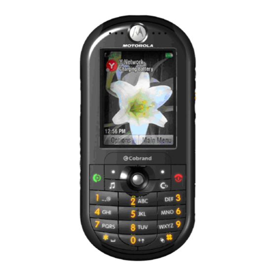
General Operation ROKR E2 General Operation Controls, Indicators, and Input/Output (I/O) Connectors The E2 telephones’ controls are located on the front and sides of the device, and on the keyboard as shown in Figures 1 and 2. handsfree. Lock keypad. -
Page 15: Camera Key
Level 1 and 2 Service Manual General Operation Camera Key Volume Keys Keypad Lock Music Memory Control Keys Card Door Connector Left Side Right Side 051864o Figure 2. Telephone Controls and Indicators Locations (Sides) Indicators, in the form of icons, are displayed on the LCD (see Figure 3). 3. -
Page 16: Menu Navigation
Recharge the battery when your phone shows Low Battery. Menu Navigation ROKR E2 telephones are equipped with an icon and graphical-based user interface. All of the phone’s features can be accessed with a 5-way navigation key that allows you to move easily through menus and select menu items. -
Page 17: Battery Information
Level 1 and 2 Service Manual General Operation provides room for entering text, viewing graphics, tapping icons, and system prompts. ➧ Whether a phone displays all indicators depends on the programming and services to which the user subscribes. Figures 4 shows the Idle Screen display. Service Provider 10:15 am Recent Calls... - Page 18 The battery date code is used for cell phone batteries that were manufactured beginning in March 2000. The following paragraphs provide more detail about the battery date code. Backend Pack Manufacturing Site (first position of battery code) A = Motorola Penang J= ESG, Chihuahua S = T.D.I Scotland B = T.D.I. Mexico K= T.D.I.
- Page 19 Level 1 and 2 Service Manual General Operation Cell Reference Vendor Size Part Number Designator Saft VHAA1200 Maxell 5.5x30x48 ICP053048G NEC-Moli 6.7x30x47.3 MK11-2293 Mitsubishi 4.4x34x56 Lipmo001 Toshiba 6.6x34x50 LGQ633450R Panasonic 6x34x50 CGP34506 Toshiba 3.9x34x56 LAB363456A NEC-Moli 6.5x22x65 MK11-2300 6.6*9.8x47.9 LP063048A Panasonic LL-AAAA HHR70QAB4...
- Page 20 9 = J = 1999 = Year of battery pack manufacture position 10 & 11 = CC = week twenty two. (backend pack) position 12 = C = Motorola, China. (Frontend Core Pack) position 13, 14 & 15 = placeholders (...) to indicate pack has not been relabeled.
-
Page 21: Operation
Level 1 and 2 Service Manual General Operation Batteries sold in China have a 16 character date code: Example: YYYYMMDDABCXXXX Where YYYYMMDD is the actual battery manufacturing date A is the line number B is the shift number (A,C is day shift; B, D is night shift) C is a serial number from A to Z XXXX is a sequence number Embedded battery packs use a 6 character date code:... - Page 22 General Operation ROKR E2 March 27, 2006 6809497A99-O...
-
Page 23: Tools And Test Equipment
Used to measure battery voltage 1. To order in North America, contact Motorola Aftermarket and Accessories Division (AAD) by phone at (800) 422-4210 or FAX (800) 622-6210; Internationally, AAD can be reached by calling (847) 538-8023 or faxing (847) 576-3023. -
Page 24: Disassembly
Disassembly Disassembly This section describes how to disassemble a E2 telephone. Tools and equipment used are listed in Table 1, preceding. Many of the integrated devices used in this equipment are vulnerable to damage from electrostatic discharge (ESD). Ensure adequate static protection is in place when handling, shipping, and servicing the internal components of this equipment. - Page 25 Level 1 and 2 Service Manual Disassembly If an SD card is present, first, push the SD Card inward to unlock it (see Figure 6), SD Card 051883o Figure 6. Unlocking the SD Card Pull the SD card out of the phone (see Figure 6). SD Card 051884o Figure 7.
-
Page 26: Removing And Replacing The Battery Cover
Disassembly Removing and Replacing the Battery Cover Ensure the phone is turned off. Remove the SD card if present. Press down on the battery cover latch on the back of the phone and slide it the direction of the arrow and then lift the battery cover away from the phone (see Figure 8). -
Page 27: Removing And Replacing The Battery
Level 1 and 2 Service Manual Disassembly Removing and Replacing the Battery Battery date codes are explained in the Battery Date Code section on page 17 Before handling the battery, please observe the battery cautions listed below. Do not handle batteries with wet or sweaty hands. Do not short the positive or negative terminals Non conductive tweezers or grasping tools are to be used for battery connector manipulation, assembly, and disassembly. -
Page 28: Removing And Replacing The Subscriber Identity Module (Sim)
Disassembly Removing and Replacing the Subscriber Identity Module (SIM) Remove the SD card, battery cover, and battery as described in the procedures. Remove the SIM from the phone by sliding it in the direction indicated as shown in Figure 10. 051871o Figure 10. -
Page 29: Removing The Side Bands
Level 1 and 2 Service Manual Disassembly Removing the Side Bands Remove the SD card, battery cover, battery and SIM as described in the procedures. With the disassembly tool, pry the side band outward and then slide the side band upward and slide as indicated to release the side bands from the phone (see Figure 11). -
Page 30: Removing And Replacing The Rear Housing
Disassembly Removing and Replacing the Rear Housing Remove the SD card, battery cover, battery, SIM, and side bands as described in the procedures. Use a T6 driver to remove 6 housing screws (see Figure 12). Set the screws aside for reuse. Screw locations Screw locations Screw locations... - Page 31 Level 1 and 2 Service Manual Disassembly Use the disassembly tool to unseat the flex connector on the transceiver PC board under the rear housing (see Figure 13). Rear housing Flex connector Disassembly tool 0511980o Figure 13. Removing the rear housing To replace, align the front and rear housings.
-
Page 32: Removing And Replacing The Camera Module
Disassembly Removing and Replacing the Camera Module Remove the SD card, battery cover, battery, SIM, side bands, rear housing, as described in the procedures. This product contains static-sensitive devices. Use anti-static handling procedures to prevent electrostatic discharge (ESD) and component damage. Use the disassembly tool to unseat the camera module connector from it’s socket on the transceiver board. -
Page 33: Removing And Replacing The Transceiver Pc Board Assembly
Level 1 and 2 Service Manual Disassembly Removing and Replacing the Transceiver PC Board Assembly Remove the SD card, battery cover, battery, SIM, side bands, rear housing, as described in the procedures. Carefully lift one side of the transceiver PC board out of the front housing. Carefully use the disassembly tool to disconnect the display module flex connector from the transceiver PC board (see Figure 15). -
Page 34: Removing And Replacing The Keypad Assembly
Disassembly Removing and Replacing the Keypad Assembly Remove the SD card, battery cover, battery, SIM, side bands, rear housing, and transceiver PC board assembly as described in the procedures. Beginning underneath the front housing, use the plastic disassembly tool to push the keypad upward out of the front housing. - Page 35 Level 1 and 2 Service Manual Disassembly Insert the straight edge of the keypad between the display lens and the display module (see Figure 17). Display lens Keypad 051992o Figure 17. Installing the Keypad Assembly Insert the rest of the keypad into the front housing. Use the keypad alignment holes to correctly align the keypad with the front housing.
-
Page 36: Removing And Replacing The Display Module Assembly
Disassembly Removing and Replacing the Display Module Assembly Remove the SD card, battery cover, battery, SIM, side bands, rear housing, transceiver PC board assembly, and keypad assembly as described in the procedures. Use the disassembly tool to lift the bottom edge of the display module assembly away from the front housing. -
Page 37: Removing The Keypad Switch Pc Board
Level 1 and 2 Service Manual Disassembly Removing the Keypad Switch PC Board Remove the SD card, battery cover, battery, SIM, stylus, rear housing, side bands, transceiver PC board, and switch lock as described in the procedures. Use the metal tweezers to release the keypad switch PC board latch on each side of the main transceiver PC board (see Figure 19). - Page 38 Disassembly Lift the keypad switch PC board away from the transceiver PC board. To replace, align the keypad switch flex connector to its socket on the trans- ceiver PC board. Gently press the keypad switch flex connector into position until the connector is properly seated in its socket.
-
Page 39: Subscriber Identity Module (Sim) And Identification Label
The MSN is an individual unit identity number and remains with the unit through- out its life. The MSN can be used to log and track a phone on Motorola's Service Center Database. The MSN is divided into 4 sections as shown in Figure 21. - Page 40 Subscriber Identity Module (SIM) and Identification Label International Mobile Station Equipment Identity (IMEI) The International Mobile station Equipment Identity (IMEI) number is an individual number unique to the PCB and is stored within the unit's memory. The IMEI uniquely identifies an individual mobile station and thereby provides a means for controlling access to GSM networks based on mobile station types or individual units.
-
Page 41: Troubleshooting
Troubleshooting Troubleshooting Manual Test Mode Motorola E2 telephones are equipped with a manual test mode capability. This allows service personnel to verify functionality and perform fault isolation by entering keypad commands. To enter the manual test command mode, a GSM / DCS test SIM must be used. - Page 42 Troubleshooting 10. Press the left soft key (a) to begin the test. Left Soft Key 060108o Figure 23. Test Parameters March 27, 2006 6809497A99-O...
-
Page 43: Troubleshooting Chart
Level 1 and 2 Service Manual Troubleshooting Troubleshooting Chart Table 3. Level 1 and 2 Troubleshooting Chart Symptom Probable Cause Verification And Remedy Measure the voltage at TP_BATT+ with battery attached. If voltage is below 3.0V, attach a charger to the phone and ensure that the phone a) Battery either discharged or 1. -
Page 44: Programming: Software Upgrade And Flexing
Part Numbers Table 3. Level 1 and 2 Troubleshooting Chart (Continued) Symptom Probable Cause Verification And Remedy Check the SIM card contacts for dirt. Clean if necessary, and check if fault has been cleared. If the contacts are clean, insert a known good 7. -
Page 45: Exploded View Diagram
Level 1 and 2 Service Manual Part Numbers The following section provides a reference for the parts associated with E2 telephones. Exploded View Diagram 051890o Figure 24. Exploded View Diagram 6809497A99-O March 27, 2006... -
Page 46: Exploded View Parts List
Part Numbers Exploded View Parts List Table 4. Exploded View Parts List Item Motorola Part Description Number Number Rear housing assembly Bluetooth antenna Acoustic booth 1.3M camera module Joystick Transceiver PCBA Side bands 0309315B35 Screws (6X) Front housing assembly Side keys... - Page 47 Level 1 and 2 Service Manual Part Numbers Table 5. Accessories (Continued) Accessory Description Part Number SD Card - 64MB SVN4594 Bluetooth Products Bluetooth Module (Stereo Music and Telephony) SYN1447 Bluetooth Headset - Oakley RAZRWIRE (Mercury: NA) - H7 98679H Bluetooth Headset - Oakley RAZRWIRE (Pewter/Black: NA) - H7 98677H Bluetooth Headset - Oakley RAZRWIRE (Platinum/Rootbeer: NA) - H7...
- Page 48 In vehicle Solutions Self Install Car Kit Universal - Mandarin - Smart Drive+ SYN0888 Self Install Car Kit Universal - Smart Car Kit - Smart Drive SYN0890 Smart Cable EMU - Motorola SYN1003 Vehicle Power Adapter EMU - VC700 SYN0847 Power Solutions...
- Page 49 1 and 2 Index Level 1 and 2 Service Manual Index ROKR E2 6809497A99-O active line indicator 16 housing cover rear, removing and replacing 30 airplane mode indicator 15 antenna, removing and replacing 27 identification international mobile station equipment identity 40...
- Page 50 Index ROKR E2 exploded view parts list 46 Transceiver PC Board Assembly 33 replacement parts 44 product changes 5 SD (Secure Digital) Card, removing and replacing 24 identification 5 serial number names 5 mechanical 39 product overview 11 service manual...
- Page 52 MOTOROLA, the Stylized M Logo, and all other trademarks indicated as such herein are trademarks of Motorola, Inc. ® Reg. U.S. Pat. & Tm. Off. © 2006 Motorola, Inc. All rights reserved. Personal Communications Sector, 789 International Parkway. Sunrise, FL 33325-8292...
Need help?
Do you have a question about the ROKR E2 and is the answer not in the manual?
Questions and answers